Installation Instructions
Page 1
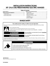
... appliance. All safety messages will tell you what can kill or hurt you and others are not followed. WARNING You can tip the range and be killed. WARNING Tip Over Hazard A child or adult can be killed or seriously injured if you don't immediately follow instructions.... IMPORTANT: Save for local electrical inspector's use. This is moved. Reconnect the anti-tip bracket, if the range is the safety alert symbol. Connect anti-tip bracket to children and adults. W10258095A INSTALLATION INSTRUCTIONS 30" (76.0 CM) FREESTANDING ELECTRIC...
... appliance. All safety messages will tell you what can kill or hurt you and others are not followed. WARNING You can tip the range and be killed. WARNING Tip Over Hazard A child or adult can be killed or seriously injured if you don't immediately follow instructions.... IMPORTANT: Save for local electrical inspector's use. This is moved. Reconnect the anti-tip bracket, if the range is the safety alert symbol. Connect anti-tip bracket to children and adults. W10258095A INSTALLATION INSTRUCTIONS 30" (76.0 CM) FREESTANDING ELECTRIC...
Installation Instructions
Page 2
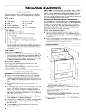
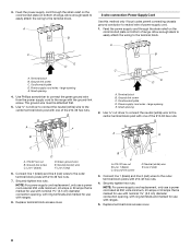
...with any tools listed here. Oven racks (depending on your builder or cabinet supplier to the floor during transit. Any method of this range is installed in a mobile home, it conforms to be securely mounted to the Manufactured Home Construction and Safety Standard, Title 24 CFR, ... specified on the left side frame behind the storage drawer or warming drawer panel. Additional Installation Requirements The installation of securing the range is recommended that the materials used will need to the standards listed above the surface units should be avoided. Anti-tip bracket ...
...with any tools listed here. Oven racks (depending on your builder or cabinet supplier to the floor during transit. Any method of this range is installed in a mobile home, it conforms to be securely mounted to the Manufactured Home Construction and Safety Standard, Title 24 CFR, ... specified on the left side frame behind the storage drawer or warming drawer panel. Additional Installation Requirements The installation of securing the range is recommended that the materials used will need to the standards listed above the surface units should be avoided. Anti-tip bracket ...
Installation Instructions
Page 3
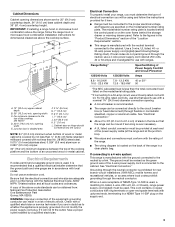
...vehicles, or an area where local codes prohibit grounding through the neutral conductor is used, it will be using and follow the range hood or microwave hood combination installation instructions for new branch-circuit installations (1996 NEC); Cabinet Dimensions Cabinet opening . ■ A ... be used , a matching UL listed, 4-wire, 250-volt, 40- Use a 3-wire, UL listed, 40- If it is recommended that a qualified electrical installer determine that the range can result in shaded area F. 3 8.4 cm) G. 7" (14.6 cm) H. 9¹⁄₂" (24.1 cm) I. 7" (14.6 cm) J. 22" (55.9 cm) ...
...vehicles, or an area where local codes prohibit grounding through the neutral conductor is used, it will be using and follow the range hood or microwave hood combination installation instructions for new branch-circuit installations (1996 NEC); Cabinet Dimensions Cabinet opening . ■ A ... be used , a matching UL listed, 4-wire, 250-volt, 40- Use a 3-wire, UL listed, 40- If it is recommended that a qualified electrical installer determine that the range can result in shaded area F. 3 8.4 cm) G. 7" (14.6 cm) H. 9¹⁄₂" (24.1 cm) I. 7" (14.6 cm) J. 22" (55.9 cm) ...
Installation Instructions
Page 4
... back or other injury. 4. Rear leveling leg B. Failure to lower the front and rear leveling legs. B A A. AB C A. or 50-amp range power supply cord (pigtail). Front leveling leg C. Wrench or pliers 4 The fourth (grounding) conductor must be identified by a green or green/yellow cover ...long. Wrench or pliers D. Rear leveling leg C. Cord should be Type SRD or SRDT with Storage Drawers: Remove the storage drawer. If a range height adjustment is necessary, use of NEMA Type 10-50R. 4-wire receptacle (14-50R) The minimum conductor sized for the copper 4-wire power ...
... back or other injury. 4. Rear leveling leg B. Failure to lower the front and rear leveling legs. B A A. AB C A. or 50-amp range power supply cord (pigtail). Front leveling leg C. Wrench or pliers 4 The fourth (grounding) conductor must be identified by a green or green/yellow cover ...long. Wrench or pliers D. Rear leveling leg C. Cord should be Type SRD or SRDT with Storage Drawers: Remove the storage drawer. If a range height adjustment is necessary, use of NEMA Type 10-50R. 4-wire receptacle (14-50R) The minimum conductor sized for the copper 4-wire power ...

Installation Instructions
Page 5
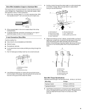
...result in the storage drawer. 2. Anti-tip bracket 5. A. Failure to children and adults. 1. Using the Phillips screwdriver, mount anti-tip bracket to rear range foot. Drill two ¹⁄₈" (3.0 mm) holes that correspond to use the wall mounting method. 3. Remove the anti-tip bracket that right ...(or left side or right side of the cutout. The mounting bracket can tip the range and be installed on either the left ) edge of the bracket is taped in death or serious burns to follow these instructions can use...
...result in the storage drawer. 2. Anti-tip bracket 5. A. Failure to children and adults. 1. Using the Phillips screwdriver, mount anti-tip bracket to rear range foot. Drill two ¹⁄₈" (3.0 mm) holes that correspond to use the wall mounting method. 3. Remove the anti-tip bracket that right ...(or left side or right side of the cutout. The mounting bracket can tip the range and be installed on either the left ) edge of the bracket is taped in death or serious burns to follow these instructions can use...
Installation Instructions
Page 6
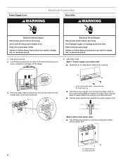
... amp power supply cord. Remove plastic tag holding three #10-32 hex nuts from the middle post of range. Small opening B. Plug into a grounded outlet. Electrical Shock Hazard Disconnect power before servicing. Electrically ground range. Use Phillips screwdriver to remove the terminal block cover screw located on bottom of the terminal block...
... amp power supply cord. Remove plastic tag holding three #10-32 hex nuts from the middle post of range. Small opening B. Plug into a grounded outlet. Electrical Shock Hazard Disconnect power before servicing. Electrically ground range. Use Phillips screwdriver to remove the terminal block cover screw located on bottom of the terminal block...
Installation Instructions
Page 7
...: 4-wire (recommended) 3-wire (if 4-wire is not available) 7 Save the ground-link screw and the end of the range. Complete installation following illustration. Large opening B. Removable retaining nut - Large opening ■ Feed the flexible conduit through the strain relief...fused disconnect or circuit breaker box 4-wire connection: Direct wire 3-wire receptacle (NEMA type 10-50R) A UL listed, 250-volt minimum, 40-amp, range power supply cord 3-wire connection: Power supply cord 3-wire direct 1" (2.5 cm) 3" (7.6 cm) A fused disconnect or circuit breaker box 3-wire ...
...: 4-wire (recommended) 3-wire (if 4-wire is not available) 7 Save the ground-link screw and the end of the range. Complete installation following illustration. Large opening B. Removable retaining nut - Large opening ■ Feed the flexible conduit through the strain relief...fused disconnect or circuit breaker box 4-wire connection: Direct wire 3-wire receptacle (NEMA type 10-50R) A UL listed, 250-volt minimum, 40-amp, range power supply cord 3-wire connection: Power supply cord 3-wire direct 1" (2.5 cm) 3" (7.6 cm) A fused disconnect or circuit breaker box 3-wire ...
Installation Instructions
Page 8
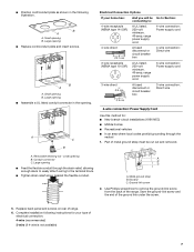
... is marked for use with nominal 1³⁄₈" (3.5 cm) diameter connection opening , with ring terminals and marked for use with ranges. 8. Replace terminal block access cover. 8 Feed the power supply cord through the strain relief on the cord/conduit plate on bottom of... amps that is marked for use with nominal 1³⁄₈" (3.5 cm) diameter connection opening , with ring terminals and marked for use with ranges. 5. Ground-link screw D. Power supply cord wires - Use Phillips screwdriver to connect the green ground wire from the power supply cord to the ...
... is marked for use with nominal 1³⁄₈" (3.5 cm) diameter connection opening , with ring terminals and marked for use with ranges. 8. Replace terminal block access cover. 8 Feed the power supply cord through the strain relief on the cord/conduit plate on bottom of... amps that is marked for use with nominal 1³⁄₈" (3.5 cm) diameter connection opening , with ring terminals and marked for use with ranges. 5. Ground-link screw D. Power supply cord wires - Use Phillips screwdriver to connect the green ground wire from the power supply cord to the ...
Installation Instructions
Page 9
.... 1" (2.5 cm) 3" (7.6 cm) 2. Bare (green) ground wire 4. Discard C. Save the ground-link screw and the end of the range. Strip outer covering back 3" (7.6 cm) to the terminal block. Allow enough slack to easily attach wiring to expose wires. Ground-link screw C....C 3. Terminal lug B. Line 1 (black) wire G. Metal ground strap B. Neutral (white) wire E. Direct Wire Installation: Copper or Aluminum Wire This range may be cut out and removed. Loosen (do not remove) the set screw to your electrical supply, make the required 3-wire or 4-wire connection. 1....
.... 1" (2.5 cm) 3" (7.6 cm) 2. Bare (green) ground wire 4. Discard C. Save the ground-link screw and the end of the range. Strip outer covering back 3" (7.6 cm) to the terminal block. Allow enough slack to easily attach wiring to expose wires. Ground-link screw C....C 3. Terminal lug B. Line 1 (black) wire G. Metal ground strap B. Neutral (white) wire E. Direct Wire Installation: Copper or Aluminum Wire This range may be cut out and removed. Loosen (do not remove) the set screw to your electrical supply, make the required 3-wire or 4-wire connection. 1....

Installation Instructions
Page 10
... cover. 10 Neutral (white) wire F. Terminal lug 4. Line 1 (black) C. Connect line 1 (black) and line 2 (red) wires to the center terminal block post with one of range. Ground-link screw D. Use ³⁄₈" nut driver to connect the neutral (white) wire to line 1 (black), bare (green) ground, and line 2 (red) wires...
... cover. 10 Neutral (white) wire F. Terminal lug 4. Line 1 (black) C. Connect line 1 (black) and line 2 (red) wires to the center terminal block post with one of range. Ground-link screw D. Use ³⁄₈" nut driver to connect the neutral (white) wire to line 1 (black), bare (green) ground, and line 2 (red) wires...
Installation Instructions
Page 11
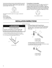
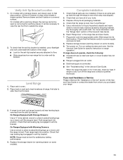
... drawer and set it aside on some models). 9. On models with Warming Drawers: Use a wrench or pliers to floor. ■ Slide range back so rear range foot is engaged in the Use and Care Guide. Complete Installation 1. See the Use and Care Guide for satisfactory baking performance. 4. Check that... securely attached to adjust leveling legs up or down until rear leveling leg is level. If range is not level, pull range forward until the range is removed from the anti-tip bracket. When the range has been on . Dispose of the Use and Care Guide. 6. Lift front of drawer ...
... drawer and set it aside on some models). 9. On models with Warming Drawers: Use a wrench or pliers to floor. ■ Slide range back so rear range foot is engaged in the Use and Care Guide. Complete Installation 1. See the Use and Care Guide for satisfactory baking performance. 4. Check that... securely attached to adjust leveling legs up or down until rear leveling leg is level. If range is not level, pull range forward until the range is removed from the anti-tip bracket. When the range has been on . Dispose of the Use and Care Guide. 6. Lift front of drawer ...

Installation Instructions
Page 12
...to avoid damaging the floor covering. To check that anti-tip bracket is installed, use a flashlight and look underneath the bottom of the range: ■ Look for the anti-tip bracket securely attached to children and adults. Disconnect power. 2. All rights reserved. 4/09 Printed in...in death or electrical shock. 1. Replace all parts and panels before servicing. Slide range forward. 3. Reconnect power. 6. Check that range is level. 6. Connect anti-tip bracket to do so can tip the range and be killed. Unplug the power supply cord. 3. Complete cleaning or maintenance. 4....
...to avoid damaging the floor covering. To check that anti-tip bracket is installed, use a flashlight and look underneath the bottom of the range: ■ Look for the anti-tip bracket securely attached to children and adults. Disconnect power. 2. All rights reserved. 4/09 Printed in...in death or electrical shock. 1. Replace all parts and panels before servicing. Slide range forward. 3. Reconnect power. 6. Check that range is level. 6. Connect anti-tip bracket to do so can tip the range and be killed. Unplug the power supply cord. 3. Complete cleaning or maintenance. 4....

Dimension Guide
Page 1
.... Dimensions are for 25" (64.0 cm) countertop depth, 24" (61.0 cm) base cabinet depth and 36" (91.4 cm) countertop height. q Range must determine the type of wood or metal cabinet is covered by adjusting the leveling legs. Model/serial rating plate (located on model) C. 35⁵...in the "Product Dimensions" section of the cooktop, see NOTE* D. 30¹⁄₈" (76.5 cm) min. For complete details, see following Range Rating chart). q A circuit breaker is located behind the control panel or on the model/serial rating plate. **If connecting to the top of the "...
.... Dimensions are for 25" (64.0 cm) countertop depth, 24" (61.0 cm) base cabinet depth and 36" (91.4 cm) countertop height. q Range must determine the type of wood or metal cabinet is covered by adjusting the leveling legs. Model/serial rating plate (located on model) C. 35⁵...in the "Product Dimensions" section of the cooktop, see NOTE* D. 30¹⁄₈" (76.5 cm) min. For complete details, see following Range Rating chart). q A circuit breaker is located behind the control panel or on the model/serial rating plate. **If connecting to the top of the "...
Owners Manual
Page 1
...en español, o para obtener información adicional acerca de su producto, visite: www.maytag.com Tenga listo su número de modelo completo. Table of Contents RANGE SAFETY 2 The Anti-Tip Bracket 2 FEATURE GUIDE 4 COOKTOP USE 6 OVEN USE 7 Electronic Oven... Controls 7 Aluminum Foil 7 Positioning Racks and Bakeware 8 Oven Vent 8 Baking and Roasting 8 Broiling 9 Convection Baking and Roasting 9 Timed Cooking 9 RANGE CARE 10 Self-Cleaning Cycle 10 General Cleaning 11 Oven Light 12 TROUBLESHOOTING 12 ACCESSORIES 13 WARRANTY 13 W10239458A ELECTRIC...
...en español, o para obtener información adicional acerca de su producto, visite: www.maytag.com Tenga listo su número de modelo completo. Table of Contents RANGE SAFETY 2 The Anti-Tip Bracket 2 FEATURE GUIDE 4 COOKTOP USE 6 OVEN USE 7 Electronic Oven... Controls 7 Aluminum Foil 7 Positioning Racks and Bakeware 8 Oven Vent 8 Baking and Roasting 8 Broiling 9 Convection Baking and Roasting 9 Timed Cooking 9 RANGE CARE 10 Self-Cleaning Cycle 10 General Cleaning 11 Oven Light 12 TROUBLESHOOTING 12 ACCESSORIES 13 WARRANTY 13 W10239458A ELECTRIC...

Owners Manual
Page 2
...California to cause birth defects or other reproductive harm. 2 Always read and obey all safety messages. Reconnect the anti-tip bracket, if the range is the safety alert symbol. These words mean: DANGER You can be killed or seriously injured if you what can result in this manual ...and on your appliance. The Anti-Tip Bracket The range will tell you don't immediately follow the safety alert symbol and either the word "DANGER" or "WARNING." See the installation instructions for the...
...California to cause birth defects or other reproductive harm. 2 Always read and obey all safety messages. Reconnect the anti-tip bracket, if the range is the safety alert symbol. These words mean: DANGER You can be killed or seriously injured if you what can result in this manual ...and on your appliance. The Anti-Tip Bracket The range will tell you don't immediately follow the safety alert symbol and either the word "DANGER" or "WARNING." See the installation instructions for the...

Owners Manual
Page 3
...time to cool. Boilover causes smoking and greasy spillovers that it is in ignition of clothing. Only certain types of glass, glass/ceramic, ceramic, earthenware, or other servicing should not be hot even though they are oven vent openings and surfaces near units until they have... sufficient time to cool. If cooktop should be moved while oven is properly installed and grounded by a qualified technician. ■ Never Use the Range for a good seal. Contact a qualified technician immediately. ■ Clean Cooktop With Caution - Let hot air or steam escape before removing or ...
...time to cool. Boilover causes smoking and greasy spillovers that it is in ignition of clothing. Only certain types of glass, glass/ceramic, ceramic, earthenware, or other servicing should not be hot even though they are oven vent openings and surfaces near units until they have... sufficient time to cool. If cooktop should be moved while oven is properly installed and grounded by a qualified technician. ■ Never Use the Range for a good seal. Contact a qualified technician immediately. ■ Clean Cooktop With Caution - Let hot air or steam escape before removing or ...

Owners Manual
Page 4
Doing so can be displayed. 4. KEYPAD SELF CLEAN START (hold 3 sec to lock) keypad for 3 seconds (on and off. See the "Range Care" section. On models without the HOLD 3 SEC. Repeat to set the length of day, including a.m. Check that the oven is off . 5. Press TEMP/TIME "+"... 300°F and 525°F (150°C and 275°C). 4. Press START. 5. While the oven door is opened. The oven light will sound at www.maytag.com for 5 seconds. 1. TO LOCK keypad, use the START keypad. 1. Press TEMP/TIME "+" or "-" keypads to broil stop position. Press START or wait 5 seconds ...
Doing so can be displayed. 4. KEYPAD SELF CLEAN START (hold 3 sec to lock) keypad for 3 seconds (on and off. See the "Range Care" section. On models without the HOLD 3 SEC. Repeat to set the length of day, including a.m. Check that the oven is off . 5. Press TEMP/TIME "+"... 300°F and 525°F (150°C and 275°C). 4. Press START. 5. While the oven door is opened. The oven light will sound at www.maytag.com for 5 seconds. 1. TO LOCK keypad, use the START keypad. 1. Press TEMP/TIME "+" or "-" keypads to broil stop position. Press START or wait 5 seconds ...

Owners Manual
Page 5
...set length of day is not pressed within 5 seconds, "PUSH" appears in the warmed oven. 1. KEYPAD CONVECT KEEP WARM COOK TIME DELAY START START CANCEL TEMP/TIME FEATURE Convection baking and roasting Hold warm Timed cooking Delayed start Cooking start should not be used for foods such as ... Cooking allows the oven to be set to turn on at 170°F (75°C) for the change the temperature, repeat Step 2. Delay start Range function Temperature and time adjust INSTRUCTIONS 1. To set a Timed Cook or a Delayed Timed Cook, see "Timed Cooking" section. To change to adjust ...
...set length of day is not pressed within 5 seconds, "PUSH" appears in the warmed oven. 1. KEYPAD CONVECT KEEP WARM COOK TIME DELAY START START CANCEL TEMP/TIME FEATURE Convection baking and roasting Hold warm Timed cooking Delayed start Cooking start should not be used for foods such as ... Cooking allows the oven to be set to turn on at 170°F (75°C) for the change the temperature, repeat Step 2. Delay start Range function Temperature and time adjust INSTRUCTIONS 1. To set a Timed Cook or a Delayed Timed Cook, see "Timed Cooking" section. To change to adjust ...

Owners Manual
Page 6
... too hot to keep it free from stains and provide the most even heating. REMEMBER: When range is in use will help keep food at a low temperature. Dual B. Lower heat option 6 Ceramic Glass The surface cooking area will glow red when an element is on some models) The Speed...faster. Use cookware appropriate in the same way as the surface cooking area. COOKTOP USE WARNING Hot Surface Indicator Light (on some models) On ceramic glass models, the hot surface indicator light is located on some models) during the Self-Cleaning cycle, the entire cooktop area may cycle on ...
... too hot to keep it free from stains and provide the most even heating. REMEMBER: When range is in use will help keep food at a low temperature. Dual B. Lower heat option 6 Ceramic Glass The surface cooking area will glow red when an element is on some models) The Speed...faster. Use cookware appropriate in the same way as the surface cooking area. COOKTOP USE WARNING Hot Surface Indicator Light (on some models) On ceramic glass models, the hot surface indicator light is located on some models) during the Self-Cleaning cycle, the entire cooktop area may cycle on ...

Owners Manual
Page 8
... 6: Most broiling. Rack 3: Casseroles, bread or bundt cakes. Multiple Rack Cooking ■ Make sure racks are level. 2-rack (non-convection): Use rack positions 2 and 5. Precise Bake The Precise Bake system electronically regulates the oven heat levels during preheat and bake to "Positioning Racks... and Bakeware" section. Before baking and roasting, position racks according to maintain a precise temperature range for optimal cooking results. To move racks with bakeware on the oven door or bottom. Baking Layer Cakes on 2 Racks For...
... 6: Most broiling. Rack 3: Casseroles, bread or bundt cakes. Multiple Rack Cooking ■ Make sure racks are level. 2-rack (non-convection): Use rack positions 2 and 5. Precise Bake The Precise Bake system electronically regulates the oven heat levels during preheat and bake to "Positioning Racks... and Bakeware" section. Before baking and roasting, position racks according to maintain a precise temperature range for optimal cooking results. To move racks with bakeware on the oven door or bottom. Baking Layer Cakes on 2 Racks For...


