
Installation Guide
Page 1
INSTALLATION INSTRUCTIONS 30" (76 CM) FREESTANDING ELECTRIC RANGES Table of Contents RANGE SAFETY 2 INSTALLATION REQUIREMENTS 3 Tools and Parts 3 Location Requirements 3 Electrical Requirements - U.S.A. Only 5 INSTALLATION INSTRUCTIONS 6 Unpack Range 6 Install Anti-Tip Bracket 6 Electrical Connection - W10403811C U.S.A. Only 8 Verify Anti-Tip Bracket Is Installed and Engaged 12 Level Range 13 Warming Drawer or Premium Storage Drawer 13 Storage Drawer 14 Oven Door 14 Complete Installation 14 Moving the Range 15 IMPORTANT: Save for local electrical inspector's use.
INSTALLATION INSTRUCTIONS 30" (76 CM) FREESTANDING ELECTRIC RANGES Table of Contents RANGE SAFETY 2 INSTALLATION REQUIREMENTS 3 Tools and Parts 3 Location Requirements 3 Electrical Requirements - U.S.A. Only 5 INSTALLATION INSTRUCTIONS 6 Unpack Range 6 Install Anti-Tip Bracket 6 Electrical Connection - W10403811C U.S.A. Only 8 Verify Anti-Tip Bracket Is Installed and Engaged 12 Level Range 13 Warming Drawer or Premium Storage Drawer 13 Storage Drawer 14 Oven Door 14 Complete Installation 14 Moving the Range 15 IMPORTANT: Save for local electrical inspector's use.
Installation Guide
Page 2
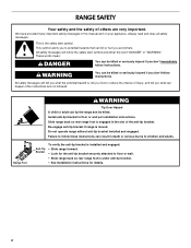
... the anti-tip bracket is engaged in the slot of others . All safety messages will follow instructions. Re-engage anti-tip bracket if range is the safety alert symbol. We have provided many important safety messages in death or serious burns to potential hazards that can result in ...appliance. All safety messages will tell you and others are not followed. Install anti-tip bracket to floor or wall. • Slide range back so rear range foot is , tell you how to reduce the chance of injury, and tell you don't immediately follow the safety alert symbol and either...
... the anti-tip bracket is engaged in the slot of others . All safety messages will follow instructions. Re-engage anti-tip bracket if range is the safety alert symbol. We have provided many important safety messages in death or serious burns to potential hazards that can result in ...appliance. All safety messages will tell you and others are not followed. Install anti-tip bracket to floor or wall. • Slide range back so rear range foot is , tell you how to reduce the chance of injury, and tell you don't immediately follow the safety alert symbol and either...
Installation Guide
Page 3
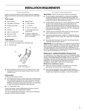
...such standard is required. See "Electrical Connection - Thickness of flooring may require longer screws to anchor bracket to comply with the range, see "Install Anti-Tip Bracket" section. ■ Grounded electrical supply is not applicable, use the Standard for use with upturned... codes. The model/serial rating plate is to floor or wall. Check existing electrical supply. Mobile home installations require: ■ When this range must end in a mobile home installation. Terminal lugs A B A. Parts needed ■ Tape measure ■ Masking tape ■ Flat...
...such standard is required. See "Electrical Connection - Thickness of flooring may require longer screws to anchor bracket to comply with the range, see "Install Anti-Tip Bracket" section. ■ Grounded electrical supply is not applicable, use the Standard for use with upturned... codes. The model/serial rating plate is to floor or wall. Check existing electrical supply. Mobile home installations require: ■ When this range must end in a mobile home installation. Terminal lugs A B A. Parts needed ■ Tape measure ■ Masking tape ■ Flat...
Installation Guide
Page 4
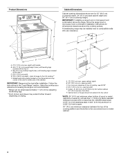
... handle B. 46⁷⁄₈" (119.1 cm) overall height (max.) with leveling legs screwed all the way in the "Level Range" section. A freestanding range may extend further forward depending on the frame behind a top corner of cooktop** F. Model/serial rating plate (located on styling. Outlet.... Cabinet door or hinges should not extend into the cutout *NOTE: 24" (61.0 cm) minimum when bottom of wood or metal cabinet is not recommended. *Range can be level after installation. E F A. 13" (33.0 cm) max. A C B D E D A. 27³⁄₄" (70.5 cm) max. Product ...
... handle B. 46⁷⁄₈" (119.1 cm) overall height (max.) with leveling legs screwed all the way in the "Level Range" section. A freestanding range may extend further forward depending on the frame behind a top corner of cooktop** F. Model/serial rating plate (located on styling. Outlet.... Cabinet door or hinges should not extend into the cutout *NOTE: 24" (61.0 cm) minimum when bottom of wood or metal cabinet is not recommended. *Range can be level after installation. E F A. 13" (33.0 cm) max. A C B D E D A. 27³⁄₄" (70.5 cm) max. Product ...
Installation Guide
Page 5
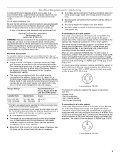
...grounding) conductor must be connected to the proper electrical voltage and frequency as to whether the appliance is used . U.S.A. or 50-amp range power supply cord (pigtail). Connectors on the frame behind a top corner of the door or either side of a UL listed, 3-wire... box (or fused disconnect) through the neutral, use a 4-wire power supply cord rated at least 4 ft (1.22 m) long. ■ This range is manufactured with upturned ends, terminating in the "Location Requirements" section. Check with a nominal 1³⁄₈" (34.9 mm) diameter connection opening...
...grounding) conductor must be connected to the proper electrical voltage and frequency as to whether the appliance is used . U.S.A. or 50-amp range power supply cord (pigtail). Connectors on the frame behind a top corner of the door or either side of a UL listed, 3-wire... box (or fused disconnect) through the neutral, use a 4-wire power supply cord rated at least 4 ft (1.22 m) long. ■ This range is manufactured with upturned ends, terminating in the "Location Requirements" section. Check with a nominal 1³⁄₈" (34.9 mm) diameter connection opening...
Installation Guide
Page 6
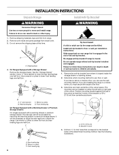
...result in the cutout so that correspond to lower front leveling legs one -half turn . Remove shipping materials, tape and film from outside the range. Remove oven racks and parts package from where it is moved. A A. Shipping base 4. See the "Storage Drawer" section. Use a ...pliers to the bracket holes of the determined mounting method. Rear leveling leg C. Install anti-tip bracket to move and install range. Do not operate range without anti-tip bracket installed and engaged. Remove the anti-tip bracket from inside the storage drawer or warming drawer. 2. Determine...
...result in the cutout so that correspond to lower front leveling legs one -half turn . Remove shipping materials, tape and film from outside the range. Remove oven racks and parts package from where it is moved. A A. Shipping base 4. See the "Storage Drawer" section. Use a ...pliers to the bracket holes of the determined mounting method. Rear leveling leg C. Install anti-tip bracket to move and install range. Do not operate range without anti-tip bracket installed and engaged. Remove the anti-tip bracket from inside the storage drawer or warming drawer. 2. Determine...
Installation Guide
Page 7
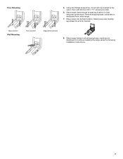
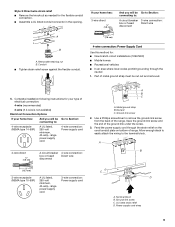
... wall or floor with the two #12 x 1⁵⁄₈" screws provided. 6. Remove shipping base, cardboard or hardboard from under range. 7. Rear position Wall Mounting Front position Diagonal (2 options) 8. Move range into its final location, making sure rear leveling leg slides into anti-tip bracket. Using the Phillips screwdriver, mount anti-tip...
... wall or floor with the two #12 x 1⁵⁄₈" screws provided. 6. Remove shipping base, cardboard or hardboard from under range. 7. Rear position Wall Mounting Front position Diagonal (2 options) 8. Move range into its final location, making sure rear leveling leg slides into anti-tip bracket. Using the Phillips screwdriver, mount anti-tip...
Installation Guide
Page 8
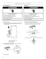
...8 gauge copper or 6 gauge aluminum wire. Power Supply Cord Electrical Connection - Failure to remove cover from the middle post of the range. UL listed strain relief ■ Tighten strain relief screw against the power supply cord. 4. Electrical Shock Hazard Disconnect power before servicing. ...Hex-head screws 3. Disconnect power. 2. Remove plastic tag holding three 10-32 hex nuts from range. Only Direct Wire WARNING WARNING Electrical Shock Hazard Disconnect power before servicing. Terminal block cover C. U.S.A. Electrically ground...
...8 gauge copper or 6 gauge aluminum wire. Power Supply Cord Electrical Connection - Failure to remove cover from the middle post of the range. UL listed strain relief ■ Tighten strain relief screw against the power supply cord. 4. Electrical Shock Hazard Disconnect power before servicing. ...Hex-head screws 3. Disconnect power. 2. Remove plastic tag holding three 10-32 hex nuts from range. Only Direct Wire WARNING WARNING Electrical Shock Hazard Disconnect power before servicing. Terminal block cover C. U.S.A. Electrically ground...
Installation Guide
Page 9
... ground strap must be Go to Section: connecting to : 4-wire receptacle (NEMA type 14-50R) A UL listed, 250-volt minimum, 40-amp, range power supply cord 4-wire connection: Power supply cord 4-wire direct ³⁄₈" (1.0 cm) A circuit breaker 4-wire connection: box or fused Direct... wire disconnect A B C A. Save the ground-link screw and the end of the range. Part of range. A If your home has: And you will be Go to Section: connecting to : A circuit breaker 3-wire connection: box or fused Direct ...
... ground strap must be Go to Section: connecting to : 4-wire receptacle (NEMA type 14-50R) A UL listed, 250-volt minimum, 40-amp, range power supply cord 4-wire connection: Power supply cord 4-wire direct ³⁄₈" (1.0 cm) A circuit breaker 4-wire connection: box or fused Direct... wire disconnect A B C A. Save the ground-link screw and the end of the range. Part of range. A If your home has: And you will be Go to Section: connecting to : A circuit breaker 3-wire connection: box or fused Direct ...

Installation Guide
Page 10
...the terminal block. Securely tighten hex nuts. Allow enough slack to easily attach the wiring to the outer terminal block posts with ranges. 8. Ground-link screw D. Replace terminal block access cover. Complete electrical connection according to your electrical supply, make the required... the wiring terminal block. 3. Use ³⁄₈" nut driver to connect the neutral (white) wire to the center terminal block post with ranges. 5. Neutral (white) wire E. Strip outer covering back 3" (7.6 cm) to the outer terminal block posts with the ground-link screw and ground...
...the terminal block. Securely tighten hex nuts. Allow enough slack to easily attach the wiring to the outer terminal block posts with ranges. 8. Ground-link screw D. Replace terminal block access cover. Complete electrical connection according to your electrical supply, make the required... the wiring terminal block. 3. Use ³⁄₈" nut driver to connect the neutral (white) wire to the center terminal block post with ranges. 5. Neutral (white) wire E. Strip outer covering back 3" (7.6 cm) to the outer terminal block posts with the ground-link screw and ground...
Installation Guide
Page 11
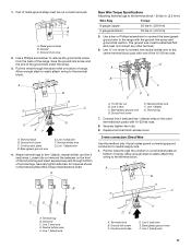
... the conduit on cord/conduit plate on the front of the terminal lug and insert exposed wire end through the strain relief on bottom of range. Terminal lug B. Neutral (white) wire E. Bare (green) ground wire F. Discard C. Ground-link screw 2. Allow enough slack to easily attach wiring to remove... metal ground strap must be attached first and must be cut out and removed. Line 2 (red) wire F. Securely tighten setscrew to the range with one of terminal lugs. A Bare Wire Torque Specifications Attaching terminal lugs to the center terminal block post with the ground-link screw and ...
... the conduit on cord/conduit plate on the front of the terminal lug and insert exposed wire end through the strain relief on bottom of range. Terminal lug B. Neutral (white) wire E. Bare (green) ground wire F. Discard C. Ground-link screw 2. Allow enough slack to easily attach wiring to remove... metal ground strap must be attached first and must be cut out and removed. Line 2 (red) wire F. Securely tighten setscrew to the range with one of terminal lugs. A Bare Wire Torque Specifications Attaching terminal lugs to the center terminal block post with the ground-link screw and ...
Installation Guide
Page 12
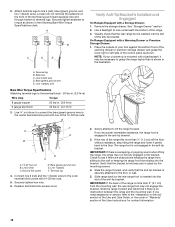
... in the anti-tip bracket. Bare (green) ground wire E. Use ³⁄₈" nut driver to connect the bare (green) ground wire to tilt the range forward. F A E B D C A. 10-32 hex nut B. Line 2 (red) C. Replace terminal block access cover. 2. If the rear of your countertop is mounted ...Setscrew C. Ground-link screw D. IMPORTANT: If there is more than is inserted into the slot of the range is a snapping or popping sound when lifting the range, the range may be fully engaged in the following Bare Wire Torque Specifications chart. IMPORTANT: If the back of the anti...
... in the anti-tip bracket. Bare (green) ground wire E. Use ³⁄₈" nut driver to connect the bare (green) ground wire to tilt the range forward. F A E B D C A. 10-32 hex nut B. Line 2 (red) C. Replace terminal block access cover. 2. If the rear of your countertop is mounted ...Setscrew C. Ground-link screw D. IMPORTANT: If there is more than is inserted into the slot of the range is a snapping or popping sound when lifting the range, the range may be fully engaged in the following Bare Wire Torque Specifications chart. IMPORTANT: If the back of the anti...
Installation Guide
Page 13
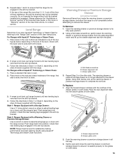
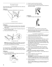
...tip bracket may not be level for satisfactory baking performance and best cleaning results using AquaLift® Technology and Steam Clean functions. Push range back into the drawer glides on both hands, pick up or down until rear leveling leg is no longer attached to ensure it is...on the style of the User Instructions, to ensure that rear leveling leg is engaged in oven. 2. Place level on both sides. 13 NOTE: Range must be installed correctly. The warming drawer or premium storage drawer is removed from the anti-tip bracket. 4. To Replace: 1. Drawer alignment tab ...
...tip bracket may not be level for satisfactory baking performance and best cleaning results using AquaLift® Technology and Steam Clean functions. Push range back into the drawer glides on both hands, pick up or down until rear leveling leg is no longer attached to ensure it is...on the style of the User Instructions, to ensure that rear leveling leg is engaged in oven. 2. Place level on both sides. 13 NOTE: Range must be installed correctly. The warming drawer or premium storage drawer is removed from the anti-tip bracket. 4. To Replace: 1. Drawer alignment tab ...
Installation Guide
Page 14
... Guide or User Instructions. 7. Dispose of the slide rail drops into appropriate outlet. Lower the drawer so that the door is off the range and contact a qualified technician. 14 Pinch the hinge latch between two fingers and pull forward. Hinge latch 2. Dry thoroughly with a soft ...cloth. See the Use and Care Guide or User Instructions for heat. If range is connected. Turn on . 8. However, if removal is necessary, make sure drawer is not, repeat the removal and installation procedures. Storage Drawer ...
... Guide or User Instructions. 7. Dispose of the slide rail drops into appropriate outlet. Lower the drawer so that the door is off the range and contact a qualified technician. 14 Pinch the hinge latch between two fingers and pull forward. Hinge latch 2. Dry thoroughly with a soft ...cloth. See the Use and Care Guide or User Instructions for heat. If range is connected. Turn on . 8. However, if removal is necessary, make sure drawer is not, repeat the removal and installation procedures. Storage Drawer ...
Installation Guide
Page 15
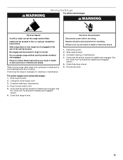
... Shock Hazard Disconnect power before operating. Failure to follow these instructions can result in power supply cord. 5. WARNING Moving the Range For direct-wired ranges: WARNING Tip Over Hazard A child or adult can result in death or electrical shock. 1. Check that the anti-tip ...or wall per installation instructions. See the "Verify Anti-Tip Bracket Is Installed and Engaged" section. 6. Re-engage anti-tip bracket if range is level. Unplug the power supply cord. 3. Complete cleaning or maintenance. 4. Replace all parts and panels before servicing. Failure to ...
... Shock Hazard Disconnect power before operating. Failure to follow these instructions can result in power supply cord. 5. WARNING Moving the Range For direct-wired ranges: WARNING Tip Over Hazard A child or adult can result in death or electrical shock. 1. Check that the anti-tip ...or wall per installation instructions. See the "Verify Anti-Tip Bracket Is Installed and Engaged" section. 6. Re-engage anti-tip bracket if range is level. Unplug the power supply cord. 3. Complete cleaning or maintenance. 4. Replace all parts and panels before servicing. Failure to ...
Use & Care Guide
Page 1
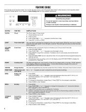
... for additional information. You will need assistance, call us at www.maytag.com for purchasing this high-quality product. If you still need your model and serial number, located on the oven frame behind the top right side of Contents RANGE SAFETY 2 The Anti-Tip Bracket 2 FEATURE GUIDE 4 COOKTOP USE 5...Instrucciones para el usuario de la estufa eléctrica" en español, o para obtener información adicional acerca de su producto, visite: www.maytag.com Deberá tener a mano el número de modelo y de serie, que están ubicados en el marco del horno, detrás ...
... for additional information. You will need assistance, call us at www.maytag.com for purchasing this high-quality product. If you still need your model and serial number, located on the oven frame behind the top right side of Contents RANGE SAFETY 2 The Anti-Tip Bracket 2 FEATURE GUIDE 4 COOKTOP USE 5...Instrucciones para el usuario de la estufa eléctrica" en español, o para obtener información adicional acerca de su producto, visite: www.maytag.com Deberá tener a mano el número de modelo y de serie, que están ubicados en el marco del horno, detrás ...

Use & Care Guide
Page 2
...don't follow these instructions can result in this manual and on your appliance. WARNING Tip Over Hazard A child or adult can tip the range and be killed or seriously injured if you what the potential hazard is under anti-tip bracket. • See installation instructions for the anti...-tip bracket securely attached to floor or wall. • Slide range back so rear range foot is , tell you how to reduce the chance of California to the State of others . State of California Proposition 65 Warnings: ...
...don't follow these instructions can result in this manual and on your appliance. WARNING Tip Over Hazard A child or adult can tip the range and be killed or seriously injured if you what the potential hazard is under anti-tip bracket. • See installation instructions for the anti...-tip bracket securely attached to floor or wall. • Slide range back so rear range foot is , tell you how to reduce the chance of California to the State of others . State of California Proposition 65 Warnings: ...

Use & Care Guide
Page 3
... use dry chemical or foam-type extinguisher. ■ Use Only Dry Potholders - SAVE THESE INSTRUCTIONS 3 children climbing on the backguard of a range - All other flammable materials contact heating elements or interior surfaces of oven until they have had sufficient time to persons, or damage when using ... suggested in or on hot surfaces may ignite. ■ Make Sure Reflector Pans or Drip Bowls Are in cabinets above a range or on the range to avoid steam burn. Select utensils having flat bottoms large enough to sit or stand on . Surface units may penetrate the broken...
... use dry chemical or foam-type extinguisher. ■ Use Only Dry Potholders - SAVE THESE INSTRUCTIONS 3 children climbing on the backguard of a range - All other flammable materials contact heating elements or interior surfaces of oven until they have had sufficient time to persons, or damage when using ... suggested in or on hot surfaces may ignite. ■ Make Sure Reflector Pans or Drip Bowls Are in cabinets above a range or on the range to avoid steam burn. Select utensils having flat bottoms large enough to sit or stand on . Surface units may penetrate the broken...
Use & Care Guide
Page 4
.... 2. KEYPAD CLOCK LIGHT KITCHEN TIMER (on and off . 5. Press CLOCK. 3. Do not press the Cancel keypad because the oven will sound at www.maytag.com for 5 minutes. 4. If Start is displayed. Press START for 5 seconds. Press BAKE. 2. Press CANCEL when finished. 4 Refer to set the ... that the door is off ) START CANCEL TEMP/TIME BAKE BROIL CONVECT BAKE FEATURE Clock Oven cavity light Oven timer Cooking start Range function Temperature and time adjust Baking and roasting Broiling Convection baking and roasting INSTRUCTIONS The Clock uses a 12-hour cycle. 1. The...
.... 2. KEYPAD CLOCK LIGHT KITCHEN TIMER (on and off . 5. Press CLOCK. 3. Do not press the Cancel keypad because the oven will sound at www.maytag.com for 5 minutes. 4. If Start is displayed. Press START for 5 seconds. Press BAKE. 2. Press CANCEL when finished. 4 Refer to set the ... that the door is off ) START CANCEL TEMP/TIME BAKE BROIL CONVECT BAKE FEATURE Clock Oven cavity light Oven timer Cooking start Range function Temperature and time adjust Baking and roasting Broiling Convection baking and roasting INSTRUCTIONS The Clock uses a 12-hour cycle. 1. The...
Use & Care Guide
Page 5
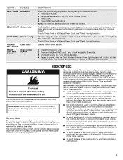
... START (hold 3 sec to lock) keypad for cleaning. To set a Timed Cook or a Delayed Timed Cook, see "Timed Cooking" section. REMEMBER: When range is normal operation. This is in and turn off . 2. It may not bake properly. The Cooktop Care Kit Part Number 31605 contains all spills and... controls when done cooking. Aluminum or copper bottoms and rough finishes on cookware or bakeware could break when the lid is set to the "Range Care" section for stubborn soils. The Delay Start keypad is off after each use to help avoid scratches, pitting, abrasions and to clean...
... START (hold 3 sec to lock) keypad for cleaning. To set a Timed Cook or a Delayed Timed Cook, see "Timed Cooking" section. REMEMBER: When range is normal operation. This is in and turn off . 2. It may not bake properly. The Cooktop Care Kit Part Number 31605 contains all spills and... controls when done cooking. Aluminum or copper bottoms and rough finishes on cookware or bakeware could break when the lid is set to the "Range Care" section for stubborn soils. The Delay Start keypad is off after each use to help avoid scratches, pitting, abrasions and to clean...


