
Installation Instructions
Page 9
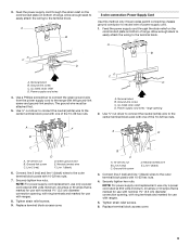
... the power supply cord through the strain relief on the cord/conduit plate on bottom of range. Connect line 2 (red) and line 1 (black) wires to the range with 10-32 hex nuts. 7. Tighten strain relief screws. 9. Neutral (white) wire E. Tighten strain relief screws. 6. Ground-link ... that is marked for use with nominal 1³⁄₈" (3.5 cm) diameter connection opening, with ring terminals and marked for use with ranges. 5. Terminal block B. Replace terminal block access cover. UL listed strain relief D. Power supply cord wires 4. Line 2 (red) C. ...
... the power supply cord through the strain relief on the cord/conduit plate on bottom of range. Connect line 2 (red) and line 1 (black) wires to the range with 10-32 hex nuts. 7. Tighten strain relief screws. 9. Neutral (white) wire E. Tighten strain relief screws. 6. Ground-link ... that is marked for use with nominal 1³⁄₈" (3.5 cm) diameter connection opening, with ring terminals and marked for use with ranges. 5. Terminal block B. Replace terminal block access cover. UL listed strain relief D. Power supply cord wires 4. Line 2 (red) C. ...

Installation Instructions
Page 10
...3-wire or 4-wire connection. 1. Strip the insulation back ³⁄₈" (1.0 cm) from the back of range. Line 2 (red) wire F. A A B B C A. Metal ground strap B. Terminal lug B. Securely ...black) wire Bare Wire Torque Specifications Attaching terminal lugs to torque as shown in . (4.0 N-m) 5. Bare (green) ground wire E. Use a Phillips screwdriver to easily attach the wiring terminal block. 3. Setscrew C. Use a hex or Phillips screwdriver to connect the bare (green) ground wire to expose wires. Strip outer covering back 3" (7.6 cm) to the range...
...3-wire or 4-wire connection. 1. Strip the insulation back ³⁄₈" (1.0 cm) from the back of range. Line 2 (red) wire F. A A B B C A. Metal ground strap B. Terminal lug B. Securely ...black) wire Bare Wire Torque Specifications Attaching terminal lugs to torque as shown in . (4.0 N-m) 5. Bare (green) ground wire E. Use a Phillips screwdriver to easily attach the wiring terminal block. 3. Setscrew C. Use a hex or Phillips screwdriver to connect the bare (green) ground wire to expose wires. Strip outer covering back 3" (7.6 cm) to the range...

Installation Instructions
Page 11
... B. Line 2 (red) wire E. Line 2 (red) C. Bare (green) ground wire E. Connect line 2 (red) and line 1 (black) wires to line 2 (red), bare (green) ground, and line 1 (black) wires. 6. Line 2 (red) C. Securely tighten setscrew to the center terminal block post with 10-32 hex nuts. 8. Line 2 (red... Bare Wire Torque Specifications Attaching terminal lugs to the outer terminal block posts with one of range. Cord/conduit plate F D. Connect line 2 (red) and line 1 (black) wires to the terminal block - 20 lbs-in. (2.3 N-m) Wire Awg Torque 8 gauge copper 6 gauge aluminum 25 ...
... B. Line 2 (red) wire E. Line 2 (red) C. Bare (green) ground wire E. Connect line 2 (red) and line 1 (black) wires to line 2 (red), bare (green) ground, and line 1 (black) wires. 6. Line 2 (red) C. Securely tighten setscrew to the center terminal block post with 10-32 hex nuts. 8. Line 2 (red... Bare Wire Torque Specifications Attaching terminal lugs to the outer terminal block posts with one of range. Cord/conduit plate F D. Connect line 2 (red) and line 1 (black) wires to the terminal block - 20 lbs-in. (2.3 N-m) Wire Awg Torque 8 gauge copper 6 gauge aluminum 25 ...
