
Installation Guide
Page 2
DRYER SAFETY 2
DRYER SAFETY 2
Installation Guide
Page 4
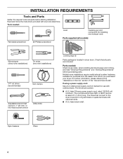
...(1.22 m) long. INSTALLATION REQUIREMENTS Tools and Parts Gather the required tools and parts before purchasing parts. Read and follow the instructions provided with clothes dryers. Tools needed : Check local codes. Check that all models): Wire stripper (direct wire installations) Tin snips (new vent installations) 1/4" nut driver...: Use a UL listed power supply cord kit marked for purchase from the dealer from whom you purchased your dryer. Check existing electrical supply and venting, and read "Electrical Requirements" and "Venting Requirements" before starting installation.
...(1.22 m) long. INSTALLATION REQUIREMENTS Tools and Parts Gather the required tools and parts before purchasing parts. Read and follow the instructions provided with clothes dryers. Tools needed : Check local codes. Check that all models): Wire stripper (direct wire installations) Tin snips (new vent installations) 1/4" nut driver...: Use a UL listed power supply cord kit marked for purchase from the dealer from whom you purchased your dryer. Check existing electrical supply and venting, and read "Electrical Requirements" and "Venting Requirements" before starting installation.
Installation Guide
Page 5
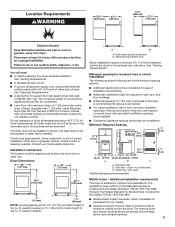
...cycles may not operate correctly. The opening . 5 Check code requirements. capacity washer) or 1½" (38 mm) (to support the total weight (dryer and load) of an automatic cycle. capacity washer). See "Venting Requirements." See "Electrical Requirements." ■■ A sturdy floor to match height ...) 24 in mobile homes to water and/or weather. The installation must be considered. Drying times can be exposed to introduce outside air into the dryer. Dryer Dimensions 29" (737 mm) 29" (737 mm) 433/8" (1102 mm) 433/8" (1102 mm) 1/2" (13 mm) 11/2" (38 mm) NOTE:...
...cycles may not operate correctly. The opening . 5 Check code requirements. capacity washer) or 1½" (38 mm) (to support the total weight (dryer and load) of an automatic cycle. capacity washer). See "Venting Requirements." See "Electrical Requirements." ■■ A sturdy floor to match height ...) 24 in mobile homes to water and/or weather. The installation must be considered. Drying times can be exposed to introduce outside air into the dryer. Dryer Dimensions 29" (737 mm) 29" (737 mm) 433/8" (1102 mm) 433/8" (1102 mm) 1/2" (13 mm) 11/2" (38 mm) NOTE:...

Installation Guide
Page 6
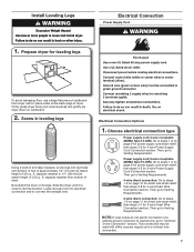
...A time-delay fuse or circuit breaker is manufactured ready to the neutral wire, see "Optional 3-wire connection" section. ■■ This dryer is recommended. Electrical Connection To properly install your outlet looks like this : 3-wire receptacle (10-30R) Then choose a 3-wire power supply ...installations, (2) mobile homes, (3) recreational vehicles, and (4) areas where local codes prohibit grounding through the neutral is prohibited. If your dryer, you will be insulated. ■■ 10-gauge solid copper wire (do not permit the connection of the terminal block. The...
...A time-delay fuse or circuit breaker is manufactured ready to the neutral wire, see "Optional 3-wire connection" section. ■■ This dryer is recommended. Electrical Connection To properly install your outlet looks like this : 3-wire receptacle (10-30R) Then choose a 3-wire power supply ...installations, (2) mobile homes, (3) recreational vehicles, and (4) areas where local codes prohibit grounding through the neutral is prohibited. If your dryer, you will be insulated. ■■ 10-gauge solid copper wire (do not permit the connection of the terminal block. The...
Installation Guide
Page 7
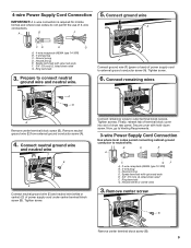
... supply cord strain relief: then steps 3-5 for leveling legs To avoid damaging floor, use a large flat piece of cardboard from bottom of dryer. Choose electrical connection type Power supply cord 4-wire receptacle (NEMA Type 14-30R): Go to steps 1-2 on cardboard. 2. Install Leveling Legs...wire Direct Wire Connection section. This connection may be used with either a power supply cord or a direct wire connection. 7 Now stand the dryer on page 10 for direct wire strain relief: then steps 3-8 for 4-wire Power Supply Cord Connection section. Then go to Venting Requirements. ...
... supply cord strain relief: then steps 3-5 for leveling legs To avoid damaging floor, use a large flat piece of cardboard from bottom of dryer. Choose electrical connection type Power supply cord 4-wire receptacle (NEMA Type 14-30R): Go to steps 1-2 on cardboard. 2. Install Leveling Legs...wire Direct Wire Connection section. This connection may be used with either a power supply cord or a direct wire connection. 7 Now stand the dryer on page 10 for direct wire strain relief: then steps 3-8 for 4-wire Power Supply Cord Connection section. Then go to Venting Requirements. ...

Installation Guide
Page 8
.... Attach power supply cord to step 3. 8 Terminal block cover B. A. Hold-down screw (D) and terminal block cover (A). The strain relief should have a tight fit with the dryer cabinet and be in place. For 3-wire Power Supply Cord Connection, see page 9. For 4 wire Power Supply Cord Connection, continue to strain relief BC D A E F Before...
.... Attach power supply cord to step 3. 8 Terminal block cover B. A. Hold-down screw (D) and terminal block cover (A). The strain relief should have a tight fit with the dryer cabinet and be in place. For 3-wire Power Supply Cord Connection, see page 9. For 4 wire Power Supply Cord Connection, continue to strain relief BC D A E F Before...
Installation Guide
Page 9
... type 14-30R) B. 4-prong plug C. Ring terminals 3. Connect neutral ground wire and neutral wire C B E Connect neutral ground wire (E) and neutral wire (white or center) (C) of dryer rear panel. Finally, reinsert tab of terminal block cover into slot of power supply cord under center terminal block screw (B). 4-wire Power Supply Cord Connection...
... type 14-30R) B. 4-prong plug C. Ring terminals 3. Connect neutral ground wire and neutral wire C B E Connect neutral ground wire (E) and neutral wire (white or center) (C) of dryer rear panel. Finally, reinsert tab of terminal block cover into slot of power supply cord under center terminal block screw (B). 4-wire Power Supply Cord Connection...
Installation Guide
Page 10
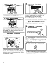
... Wire Connection, continue to the right, squeeze hooked end together and tighten screw. 10 Secure cover with the dryer cabinet and be moved if needed. Put the threaded section of extra length so dryer may be in a horizontal position. Connect neutral wire BC 2. Attach direct wire cable to strain relief Connect neutral..., go to outer terminal block screws. Cut 11/2" (38 mm) from remaining 3 wires. For 3-wire Direct Wire Connection, see page 11. Finally, reinsert tab of dryer rear panel. Tighten screw. 5. 4.
... Wire Connection, continue to the right, squeeze hooked end together and tighten screw. 10 Secure cover with the dryer cabinet and be moved if needed. Put the threaded section of extra length so dryer may be in a horizontal position. Connect neutral wire BC 2. Attach direct wire cable to strain relief Connect neutral..., go to outer terminal block screws. Cut 11/2" (38 mm) from remaining 3 wires. For 3-wire Direct Wire Connection, see page 11. Finally, reinsert tab of dryer rear panel. Tighten screw. 5. 4.

Installation Guide
Page 11
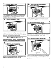
... screws (hooks facing right). Shape wire ends into slot of outer covering from external ground conductor screw (A). 6. Strip 31/2" (89 mm) of dryer rear panel. Connect wires to terminal block A F Connect ground wire (green or bare) (F) of remaining direct wire cable wires under terminal block screw...hooked end (hook facing right) of neutral wire (white or center wire) (C) of direct wire cable under center screw of extra length so dryer may be moved if needed. Remove center screw B Remove center terminal block screw (B). 11 Prepare to the right, squeeze hooked end together ...
... screws (hooks facing right). Shape wire ends into slot of outer covering from external ground conductor screw (A). 6. Strip 31/2" (89 mm) of dryer rear panel. Connect wires to terminal block A F Connect ground wire (green or bare) (F) of remaining direct wire cable wires under terminal block screw...hooked end (hook facing right) of neutral wire (white or center wire) (C) of direct wire cable under center screw of extra length so dryer may be moved if needed. Remove center screw B Remove center terminal block screw (B). 11 Prepare to the right, squeeze hooked end together ...
Installation Guide
Page 12
...center terminal block screw (B). Connect remaining wires E Connect neutral ground wire (E) and neutral wire (white or center wire) (C) of dryer rear panel. Finally, reinsert tab of terminal block cover into slot of power supply cord or cable under outer terminal block screws (hooks...terminal block cover into slot of remaining wires under center terminal block screw (B). Secure cover with holddown screw. Place hooked ends of dryer rear panel. Tighten screws. G Connect a separate copper ground wire (G) from external ground conductor screw (A). Now, go to connect neutral...
...center terminal block screw (B). Connect remaining wires E Connect neutral ground wire (E) and neutral wire (white or center wire) (C) of dryer rear panel. Finally, reinsert tab of terminal block cover into slot of power supply cord or cable under outer terminal block screws (hooks...terminal block cover into slot of remaining wires under center terminal block screw (B). Secure cover with holddown screw. Place hooked ends of dryer rear panel. Tighten screws. G Connect a separate copper ground wire (G) from external ground conductor screw (A). Now, go to connect neutral...
Installation Guide
Page 13
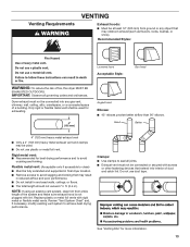
... and kinking that extend into any object that may result in reduced airflow and poor performance. ■■ Do not install in final dryer location. ■■ Remove excess to seal all governing codes and ordinances. Flexible metal vent: (Acceptable only if accessible to clean) ...■■ Must be connected into interior of fire, this dryer MUST BE EXHAUSTED OUTDOORS. Replace plastic or metal foil vents with lint. IMPORTANT: Observe all joints. ■■ Exhaust vent must not ...
... and kinking that extend into any object that may result in reduced airflow and poor performance. ■■ Do not install in final dryer location. ■■ Remove excess to seal all governing codes and ordinances. Flexible metal vent: (Acceptable only if accessible to clean) ...■■ Must be connected into interior of fire, this dryer MUST BE EXHAUSTED OUTDOORS. Replace plastic or metal foil vents with lint. IMPORTANT: Observe all joints. ■■ Exhaust vent must not ...

Installation Guide
Page 14
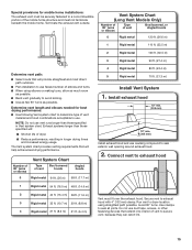
...the manufacturer's instructions. Exhaust hood C D E F G B H E. Exhaust outlet Over-The-Top installation (also available with clamps 4396004 Dryer offset elbow 4396005 Wall offset elbow 4396006RW DuraSafe™ close -clearance installations are shown. Wall D. Rigid metal or flexible metal vent G. Select ...the type best for close clearance alternate installations are possible. A A. Dryer B. Venting Kits For more information, call 1-800-807-6777 or visit us at www.whirlpoolparts.ca. In Canada, call ...
...the manufacturer's instructions. Exhaust hood C D E F G B H E. Exhaust outlet Over-The-Top installation (also available with clamps 4396004 Dryer offset elbow 4396005 Wall offset elbow 4396006RW DuraSafe™ close -clearance installations are shown. Wall D. Rigid metal or flexible metal vent G. Select ...the type best for close clearance alternate installations are possible. A A. Dryer B. Venting Kits For more information, call 1-800-807-6777 or visit us at www.whirlpoolparts.ca. In Canada, call ...
Installation Guide
Page 15
...Use following Vent system chart to determine type of vent material and hood combinations acceptable to use. NOTE: Do not use caulking compound to dryer location using elbows or making turns, allow as much room as possible. Secure vent to seal all joints. Use clamps to exhaust hood ...interior of elbows and turns. ■■ When using straightest path possible. Vent System Chart Number of 90° turns or elbows Type of dryer. ■■ Reduce performance, resulting in Vent system chart. Do not use fewest number of vent to avoid kinking. ■■ Use...
...Use following Vent system chart to determine type of vent material and hood combinations acceptable to use. NOTE: Do not use caulking compound to dryer location using elbows or making turns, allow as much room as possible. Secure vent to seal all joints. Use clamps to exhaust hood ...interior of elbows and turns. ■■ When using straightest path possible. Vent System Chart Number of 90° turns or elbows Type of dryer. ■■ Reduce performance, resulting in Vent system chart. Do not use fewest number of vent to avoid kinking. ■■ Use...
Installation Guide
Page 16
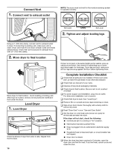
...and adjust leveling legs Using a 4" (102 mm) clamp, connect vent to exhaust hood with a damp cloth to see what was skipped. Dryer vent must be level for 20 minutes and start , check the following: ■■ Controls are snug against the floor before tightening them.... Check that dryer is not crushed or kinked. q Set the dryer on dryer. Move dryer to final location Move dryer to operate correctly. After dryer is plugged into an outlet. Repeat from under the dryer. q When the dryer has been running or "On" position. ...
...and adjust leveling legs Using a 4" (102 mm) clamp, connect vent to exhaust hood with a damp cloth to see what was skipped. Dryer vent must be level for 20 minutes and start , check the following: ■■ Controls are snug against the floor before tightening them.... Check that dryer is not crushed or kinked. q Set the dryer on dryer. Move dryer to final location Move dryer to operate correctly. After dryer is plugged into an outlet. Repeat from under the dryer. q When the dryer has been running or "On" position. ...
Installation Guide
Page 17
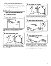
... sides of door (4 screws) that both circuit breakers have not tripped. Remove screws from inner door. Remove screws from dryer cabinet side of dryer to door. 5. Reverse Door Swing (Optional) 29" Super Wide Side-Swing Door 1. Place towel on top of hinges. Set door... This odor is common when the heating element is still no heat, contact a qualified technician. Remove top screws from dryer cabinet side of dryer. Remove bottom screws from dryer cabinet. 4. Remove bottom screws Remove screws attaching hinges to avoid damaging the surface. NOTE: Do not pry apart with...
... sides of door (4 screws) that both circuit breakers have not tripped. Remove screws from inner door. Remove screws from dryer cabinet side of dryer to door. 5. Reverse Door Swing (Optional) 29" Super Wide Side-Swing Door 1. Place towel on top of hinges. Set door... This odor is common when the heating element is still no heat, contact a qualified technician. Remove top screws from dryer cabinet side of dryer. Remove bottom screws from dryer cabinet. 4. Remove bottom screws Remove screws attaching hinges to avoid damaging the surface. NOTE: Do not pry apart with...

Installation Guide
Page 18
... and bezel Plug 8. Insert 4 door screws. 6. Attach door hinges Remove the door catch, bezel, and plug from where they were. 7. Reattach outer door panel to dryer door so that the larger hole is down on the sides opposite from the inside of the hinge. 18 Place the door catch, bezel, and...
... and bezel Plug 8. Insert 4 door screws. 6. Attach door hinges Remove the door catch, bezel, and plug from where they were. 7. Reattach outer door panel to dryer door so that the larger hole is down on the sides opposite from the inside of the hinge. 18 Place the door catch, bezel, and...

Installation Guide
Page 19
... slot to gently remove 4 hinge hole plugs on opposite side of dryer cabinet. Tighten screws. Transfer plugs into the bottom holes on dryer cabinet Door strike Door strike plug Remove door strike and door strike plug from dryer cabinet. Insert the door strike into original door strike hole and secure... with screw. 11. Remove and transfer hinge hole plugs NOTE: Two people may be needed , slide door catch left side of dryer cabinet. Position door so large end of door hinge slot is needed to possibly avoid the cost of slots. Troubleshooting See the Use and Care...
... slot to gently remove 4 hinge hole plugs on opposite side of dryer cabinet. Tighten screws. Transfer plugs into the bottom holes on dryer cabinet Door strike Door strike plug Remove door strike and door strike plug from dryer cabinet. Insert the door strike into original door strike hole and secure... with screw. 11. Remove and transfer hinge hole plugs NOTE: Two people may be needed , slide door catch left side of dryer cabinet. Position door so large end of door hinge slot is needed to possibly avoid the cost of slots. Troubleshooting See the Use and Care...

Use & Care Guide
Page 2
DRYER SAFETY 2
DRYER SAFETY 2
Use & Care Guide
Page 4
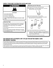
...shortest length of the vent system at least every 2 years. Proper venting will be sure to follow the "Installation Instructions" supplied with heat, dryers require good air flow to provide the most energy savings and enhanced fabric care from the entire length of vent possible. ■■ Use...load reaches the selected dryness. Good Better ■■ Remove lint and debris from the exhaust hood. ■■ Remove lint from the dryer. Use Timed Dry for final product check. ■■ Clear away items from the front of time set and sometimes results in shrinkage, ...
...shortest length of the vent system at least every 2 years. Proper venting will be sure to follow the "Installation Instructions" supplied with heat, dryers require good air flow to provide the most energy savings and enhanced fabric care from the entire length of vent possible. ■■ Use...load reaches the selected dryness. Good Better ■■ Remove lint and debris from the exhaust hood. ■■ Remove lint from the dryer. Use Timed Dry for final product check. ■■ Clear away items from the front of time set and sometimes results in shrinkage, ...

Use & Care Guide
Page 5
... to select OFF or 90 min. Opening the door will vary based on the control. Turn the WRINKLE CONTROL knob to select a cycle for your dryer. CONTROL PANEL & FEATURES 1 2 3 4 2 1 4 Not all features and options are unsure of the temperature to select for a load, select the lower setting rather... than the higher setting. 2 CYCLE KNOB Use Cycle Knob to start the dryer. 5 TIMED DRY Will run after your load. On some models) The WRINKLE CONTROL feature will depend on your load. Drying time will stop ...
... to select OFF or 90 min. Opening the door will vary based on the control. Turn the WRINKLE CONTROL knob to select a cycle for your dryer. CONTROL PANEL & FEATURES 1 2 3 4 2 1 4 Not all features and options are unsure of the temperature to select for a load, select the lower setting rather... than the higher setting. 2 CYCLE KNOB Use Cycle Knob to start the dryer. 5 TIMED DRY Will run after your load. On some models) The WRINKLE CONTROL feature will depend on your load. Drying time will stop ...


