
Use and Care Manual
Page 3
... on your appliance. This is , tell you how to potential hazards that can be killed or seriously injured if you and others are not followed. 3 DRYER SAFETY Your safety and the safety of injury, and tell you what can be killed or seriously injured if you don't immediately follow the safety...
... on your appliance. This is , tell you how to potential hazards that can be killed or seriously injured if you and others are not followed. 3 DRYER SAFETY Your safety and the safety of injury, and tell you what can be killed or seriously injured if you don't immediately follow the safety...

Use and Care Manual
Page 4
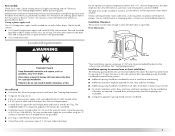
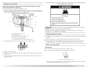
...9632; Adjustable wrench that opens to cooking oils in your dryer. Short inlet hose D. Rubber washer 4 Leveling legs (4) B. IMPORTANT SAFETY INSTRUCTIONS WARNING: To reduce the risk of fire, electric shock, or injury to persons when using the dryer. ■ Do not place items exposed to 1" (...25 mm) or hex-head socket wrench (for adjusting dryer feet) ■ Wire stripper (direct wire installations) ■ Vent ...
...9632; Adjustable wrench that opens to cooking oils in your dryer. Short inlet hose D. Rubber washer 4 Leveling legs (4) B. IMPORTANT SAFETY INSTRUCTIONS WARNING: To reduce the risk of fire, electric shock, or injury to persons when using the dryer. ■ Do not place items exposed to 1" (...25 mm) or hex-head socket wrench (for adjusting dryer feet) ■ Wire stripper (direct wire installations) ■ Vent ...
Use and Care Manual
Page 5
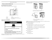
...spacing should also be large enough to allow the dryer door to water and/or weather. Check existing electrical supply and venting and see "Electrical Requirements" and "Venting Requirements" before purchasing parts. You may use with clothes dryers. Location Requirements Do not operate your local building...or SRDT and be at least 4 ft (1.22 m) long. Dryer Dimensions 43 ½" (1105 mm) You will be considered. 5 See "Electrical Requirements." ■ A sturdy floor to the "Assistance or Service" section. This dryer has been tested for the exhaust vent with elbow. Parts needed )...
...spacing should also be large enough to allow the dryer door to water and/or weather. Check existing electrical supply and venting and see "Electrical Requirements" and "Venting Requirements" before purchasing parts. You may use with clothes dryers. Location Requirements Do not operate your local building...or SRDT and be at least 4 ft (1.22 m) long. Dryer Dimensions 43 ½" (1105 mm) You will be considered. 5 See "Electrical Requirements." ■ A sturdy floor to the "Assistance or Service" section. This dryer has been tested for the exhaust vent with elbow. Parts needed )...
Use and Care Manual
Page 6
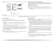
... in remodeling after 1996, and all local codes and ordinances. A time-delay fuse or circuit breaker is adequate and in "Electrical Connection - If the dryer is suitable for Mobile Home Construction and Safety, Title 24, HUD Part 280) or Standard CAN/CSA-Z240 MH. Only" ... closet or confined area C. Additional installation requirements This dryer is installed with clothes dryers. U.S.A. Side view - Closet door with the National Electrical Code, ANSI/NFPA 70-latest edition and all mobile home installations. Only It is your dryer, you will be sure that the ground path is ...
... in remodeling after 1996, and all local codes and ordinances. A time-delay fuse or circuit breaker is adequate and in "Electrical Connection - If the dryer is suitable for Mobile Home Construction and Safety, Title 24, HUD Part 280) or Standard CAN/CSA-Z240 MH. Only" ... closet or confined area C. Additional installation requirements This dryer is installed with clothes dryers. U.S.A. Side view - Closet door with the National Electrical Code, ANSI/NFPA 70-latest edition and all mobile home installations. Only It is your dryer, you will be sure that the ground path is ...
Use and Care Manual
Page 7
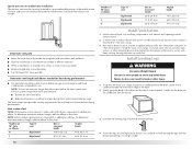
.... GROUNDING INSTRUCTIONS ■ For a grounded, cord-connected dryer: This dryer must be identified by a white cover. WARNING: Improper connection of least resistance for electric current. Do not modify the plug on the dryer. Check with a qualified electrician or service representative or personnel... if you are in doubt as to whether the dryer is properly installed and grounded in a risk of electric shock by a qualified electrician. SAVE THESE INSTRUCTIONS 7 This dryer uses a cord having an equipment-grounding conductor and a grounding plug. ...
.... GROUNDING INSTRUCTIONS ■ For a grounded, cord-connected dryer: This dryer must be identified by a white cover. WARNING: Improper connection of least resistance for electric current. Do not modify the plug on the dryer. Check with a qualified electrician or service representative or personnel... if you are in doubt as to whether the dryer is properly installed and grounded in a risk of electric shock by a qualified electrician. SAVE THESE INSTRUCTIONS 7 This dryer uses a cord having an equipment-grounding conductor and a grounding plug. ...

Use and Care Manual
Page 8
...wire receptacle 14-30R ■ Do not use Power Supply Cord Replacement Part Number 3394208. A copy of electric shock. Do not modify the plug provided with the dryer: if it is recommended that is properly installed and grounded in accordance with a CSA International Certified Power ...not fit the outlet, have a proper outlet installed by providing a path of the line. In the event of dryer's final location. Check with the Canadian Electrical Code, C22.1-latest edition and all local codes and ordinances. For further information, please reference the service numbers located ...
...wire receptacle 14-30R ■ Do not use Power Supply Cord Replacement Part Number 3394208. A copy of electric shock. Do not modify the plug provided with the dryer: if it is recommended that is properly installed and grounded in accordance with a CSA International Certified Power ...not fit the outlet, have a proper outlet installed by providing a path of the line. In the event of dryer's final location. Check with the Canadian Electrical Code, C22.1-latest edition and all local codes and ordinances. For further information, please reference the service numbers located ...
Use and Care Manual
Page 10
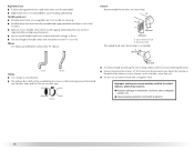
...and any screws from a 3/4" (19 mm) UL listed strain relief (UL marking on the power supply cord is not available) Electrical Connection Options If your type of the strain relief through the hole below terminal block opening , screw the removable conduit connector onto the...cable through the strain relief. The strain relief should have a tight fit with the dryer cabinet and be in a horizontal position. Tighten strain relief screw against the direct wire cable. Put the threaded section of electrical connection: 4-wire (recommended) 3-wire (if 4-wire is inside the terminal block ...
...and any screws from a 3/4" (19 mm) UL listed strain relief (UL marking on the power supply cord is not available) Electrical Connection Options If your type of the strain relief through the hole below terminal block opening , screw the removable conduit connector onto the...cable through the strain relief. The strain relief should have a tight fit with the dryer cabinet and be in a horizontal position. Tighten strain relief screw against the direct wire cable. Put the threaded section of electrical connection: 4-wire (recommended) 3-wire (if 4-wire is inside the terminal block ...
Use and Care Manual
Page 11
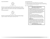
Remove center silver-colored terminal block screw. 2. Tighten screw. Ground wire (green or bare) of dryer rear panel. Center silver-colored terminal block screw F. Dotted line shows position of power supply cord to outer terminal block screws. Insert tab of terminal ... or center wire) E. ¾" (19 mm) UL listed strain relief 5. Secure cover with upturned ends F. 3/4" (19 mm) UL listed strain relief G. You have completed your electrical connection.
Remove center silver-colored terminal block screw. 2. Tighten screw. Ground wire (green or bare) of dryer rear panel. Center silver-colored terminal block screw F. Dotted line shows position of power supply cord to outer terminal block screws. Insert tab of terminal ... or center wire) E. ¾" (19 mm) UL listed strain relief 5. Secure cover with upturned ends F. 3/4" (19 mm) UL listed strain relief G. You have completed your electrical connection.
Use and Care Manual
Page 12
... D. 4-wire connection: Direct Wire IMPORTANT: A 4-wire connection is required for mobile homes and where local codes do not permit the use of extra length so dryer can be moved if needed. Cut 11/2" (38 mm) from end of outer covering from 3 remaining wires. Remove neutral ground wire from external ground conductor...
... D. 4-wire connection: Direct Wire IMPORTANT: A 4-wire connection is required for mobile homes and where local codes do not permit the use of extra length so dryer can be moved if needed. Cut 11/2" (38 mm) from end of outer covering from 3 remaining wires. Remove neutral ground wire from external ground conductor...

Use and Care Manual
Page 13
... permit connecting cabinet-ground conductor to "Venting Requirements." Neutral ground wire C. Ground wire (green or bare) of dryer rear panel. Tighten screws. Neutral wire (white or center wire) 1. Neutral ground wire C. Center silver-colored terminal block screw F.... Neutral prong D. Loosen or remove center silver-colored terminal block screw. 2. A C B D E 5. You have completed your electrical connection. Neutral wire (white or center wire) 4. C GF A. 3-wire receptacle (NEMA type 10-30R) B. 3-wire plug C. Tighten screw. Now go...
... permit connecting cabinet-ground conductor to "Venting Requirements." Neutral ground wire C. Ground wire (green or bare) of dryer rear panel. Tighten screws. Neutral wire (white or center wire) 1. Neutral ground wire C. Center silver-colored terminal block screw F.... Neutral prong D. Loosen or remove center silver-colored terminal block screw. 2. A C B D E 5. You have completed your electrical connection. Neutral wire (white or center wire) 4. C GF A. 3-wire receptacle (NEMA type 10-30R) B. 3-wire plug C. Tighten screw. Now go...
Use and Care Manual
Page 14
... moved if needed. Secure cover with holddown screw. 6. down screw. 6. You have completed your electrical connection. C A 4. Strip 31/2" (89 mm) of outer covering from end of dryer rear panel. Center silver-colored terminal block screw D. Tighten screws. 4. Insert tab of terminal block... to "Venting Requirements." 1. Place the hooked ends of dryer rear panel. Strip insulation back 1" (25 mm). Loosen or remove center silver-colored terminal block screw. 14 You have completed your electrical connection. Insert tab of terminal block cover into slot of...
... moved if needed. Secure cover with holddown screw. 6. down screw. 6. You have completed your electrical connection. C A 4. Strip 31/2" (89 mm) of outer covering from end of dryer rear panel. Center silver-colored terminal block screw D. Tighten screws. 4. Insert tab of terminal block... to "Venting Requirements." 1. Place the hooked ends of dryer rear panel. Strip insulation back 1" (25 mm). Loosen or remove center silver-colored terminal block screw. 14 You have completed your electrical connection. Insert tab of terminal block cover into slot of...
Use and Care Manual
Page 15
...terminal block screw D. Neutral wire (white or center wire) E. 3/4" (19 mm) UL listed strain relief F. Grounding path determined by calling Maytag Services. Insert tab of terminal block cover into any plastic or metal foil vent with holddown screw. 6. Connect a separate copper ground wire from ...is not plugged with lint. ■ Replace any gas vent, chimney, wall, ceiling, attic, crawlspace, or a concealed space of dryer rear panel. If this dryer MUST BE EXHAUSTED OUTDOORS. Neutral ground wire C. Fire Hazard Use a heavy metal vent. For more information, see the "Assistance or Service...
...terminal block screw D. Neutral wire (white or center wire) E. 3/4" (19 mm) UL listed strain relief F. Grounding path determined by calling Maytag Services. Insert tab of terminal block cover into any plastic or metal foil vent with holddown screw. 6. Connect a separate copper ground wire from ...is not plugged with lint. ■ Replace any gas vent, chimney, wall, ceiling, attic, crawlspace, or a concealed space of dryer rear panel. If this dryer MUST BE EXHAUSTED OUTDOORS. Neutral ground wire C. Fire Hazard Use a heavy metal vent. For more information, see the "Assistance or Service...
Use and Care Manual
Page 16
...; Flexible metal vent must be at least 12" (305 mm) from entering the home. ■ Exhaust hood must be fully extended and supported when the dryer is in enclosed walls, ceilings or floors. ■ The total length of flexible metal vent should cap the vent to seal all joints. ■ The...
...; Flexible metal vent must be at least 12" (305 mm) from entering the home. ■ Exhaust hood must be fully extended and supported when the dryer is in enclosed walls, ceilings or floors. ■ The total length of flexible metal vent should cap the vent to seal all joints. ■ The...
Use and Care Manual
Page 17
... rear offset exhaust installation B. Over-the-top installation (also available with one offset elbow) NOTE: The following kit: 8212503 Contact your installation. Dryer B. Exhaust outlet Optional exhaust installations Venting systems come in death, fire, electrical shock, or serious injury. Failure to follow these exhaust installations are available for your local dealer. This...
... rear offset exhaust installation B. Over-the-top installation (also available with one offset elbow) NOTE: The following kit: 8212503 Contact your installation. Dryer B. Exhaust outlet Optional exhaust installations Venting systems come in death, fire, electrical shock, or serious injury. Failure to follow these exhaust installations are available for your local dealer. This...
Use and Care Manual
Page 18
...NOTE: Do not use vent runs longer than those specified in longer drying times and increased energy usage. Secure vent to move and install dryer. See "Determine vent path" in back or other fastening devices that will help to either side of the mobile home structure and must ...chart. Determine vent length and elbows needed for mobile home installations The exhaust vent must be securely fastened to a noncombustible portion of the dryer is equivalent to exhaust hood. The Vent system chart provides venting requirements that extend into the leg holes by hand. Vent system chart ...
...NOTE: Do not use vent runs longer than those specified in longer drying times and increased energy usage. Secure vent to move and install dryer. See "Determine vent path" in back or other fastening devices that will help to either side of the mobile home structure and must ...chart. Determine vent length and elbows needed for mobile home installations The exhaust vent must be securely fastened to a noncombustible portion of the dryer is equivalent to exhaust hood. The Vent system chart provides venting requirements that extend into the leg holes by hand. Vent system chart ...

Use and Care Manual
Page 19
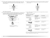
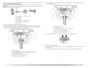
... Connect Vent 1. Using a 4" (102 mm) clamp, connect vent to the cold water faucet. Do not use old hoses. 1. Remove old rubber washer from dryer packaging under each of small hose. Attach straight end of the "Y" connector to exhaust outlet in the flexible gas line. 4. Check that the vent is... (On gas models) Check that there are on coupling by hand until it is made, remove the corner posts and cardboard. Connect Inlet Hose The dryer must be attached directly to cold water faucet, go to "Y" connector. 7. If space permits, attach the brass female end of long hose to Step...
... Connect Vent 1. Using a 4" (102 mm) clamp, connect vent to the cold water faucet. Do not use old hoses. 1. Remove old rubber washer from dryer packaging under each of small hose. Attach straight end of the "Y" connector to exhaust outlet in the flexible gas line. 4. Check that the vent is... (On gas models) Check that there are on coupling by hand until it is made, remove the corner posts and cardboard. Connect Inlet Hose The dryer must be attached directly to cold water faucet, go to "Y" connector. 7. If space permits, attach the brass female end of long hose to Step...
Use and Care Manual
Page 20
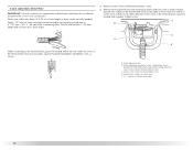
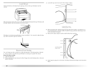
... . Lay the door on a flat, protected surface, with the inside of the dryer or work space to adjust the legs up the dryer using a wood block. Remove remaining 2 loose screws from each of the dryer. If the dryer is not level, prop up or down and check again for levelness. Use a ...these screws. Reverse Door Swing You can change your door swing from each of the 2 hinges that attach the dryer door to back. Remove the bottom screw from dryer front panel. 5. Level Dryer Check the levelness of the dryer by first placing a level on the top of plastic plugs shown 6. Location of the...
... . Lay the door on a flat, protected surface, with the inside of the dryer or work space to adjust the legs up the dryer using a wood block. Remove remaining 2 loose screws from each of the dryer. If the dryer is not level, prop up or down and check again for levelness. Use a ...these screws. Reverse Door Swing You can change your door swing from each of the 2 hinges that attach the dryer door to back. Remove the bottom screw from dryer front panel. 5. Level Dryer Check the levelness of the dryer by first placing a level on the top of plastic plugs shown 6. Location of the...
Use and Care Manual
Page 21
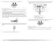
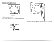
... strike and cosmetic cover on the same side of the door. A. Cosmetic cover 3. Remove the 4 screws and 2 hinges from the opposite side of the dryer door opening . 2. Install the 2 hinges to the front panel. Reverse the strike 1. Door strike B. Use the non-slotted side to attach the hinge... to the front panel of the dryer door opening from the dryer door opening . NOTE: Door strike and plugs must be on the opposite side of the dryer using 4 screws. Screw & hinge locations 21 Replace the 4 screws in the same holes. A ...
... strike and cosmetic cover on the same side of the door. A. Cosmetic cover 3. Remove the 4 screws and 2 hinges from the opposite side of the dryer door opening . 2. Install the 2 hinges to the front panel. Reverse the strike 1. Door strike B. Use the non-slotted side to attach the hinge... to the front panel of the dryer door opening from the dryer door opening . NOTE: Door strike and plugs must be on the opposite side of the dryer using 4 screws. Screw & hinge locations 21 Replace the 4 screws in the same holes. A ...

Use and Care Manual
Page 22
... buildup of lime scale may be a problem with a damp cloth to see which will go back through the water system in the door. If the dryer will not start of the water system, which step was skipped. 2. If you receive an "L2" code, there may clog different parts of its first... performance. Remove any dust. 12. Tighten all packaging materials. 4. Do not tighten screws. Test dryer operation by placing screw heads into an outlet and/or electrical supply is on . 5. Install screws in the top hinge holes in the dryer. Be sure the vent is an extra part, go away. 22 If there is...
... buildup of lime scale may be a problem with a damp cloth to see which will go back through the water system in the door. If the dryer will not start of the water system, which step was skipped. 2. If you receive an "L2" code, there may clog different parts of its first... performance. Remove any dust. 12. Tighten all packaging materials. 4. Do not tighten screws. Test dryer operation by placing screw heads into an outlet and/or electrical supply is on . 5. Install screws in the top hinge holes in the dryer. Be sure the vent is an extra part, go away. 22 If there is...
Use and Care Manual
Page 23
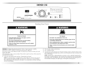
... explosion, or fire. WARNING: To reduce the risk of this appliance. Please refer to specific sections of fire, electric shock, or injury to select cycle, or open the dryer door and the display will adjust again, showing the final drying time. 23 NOTE: A default time is displayed... 3. NOTE: Your Maytag® dryer is selected. During the first few minutes of the drying process, the cycle time may not have all of the load. This manual covers several different models. Clean lint screen before operating this manual for Sensor, Timed or Steam Cycles will illuminate. Do...
... explosion, or fire. WARNING: To reduce the risk of this appliance. Please refer to specific sections of fire, electric shock, or injury to select cycle, or open the dryer door and the display will adjust again, showing the final drying time. 23 NOTE: A default time is displayed... 3. NOTE: Your Maytag® dryer is selected. During the first few minutes of the drying process, the cycle time may not have all of the load. This manual covers several different models. Clean lint screen before operating this manual for Sensor, Timed or Steam Cycles will illuminate. Do...


