
Makita DC18RD Instruction Manual
Page 3
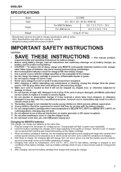
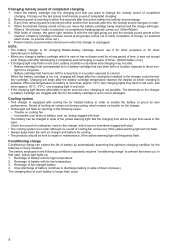
... than cord whenever disconnecting charger. 10. Do not insert a nail, wire, etc. After charging or before attempting any way; Plug the charger into USB power supply port. ENGLISH SPECIFICATIONS Model DC18RD Input A.C. 120 V 50 - 60 Hz / 50/60 Hz Output For MAKITA Battery For USB Device D.C. 7.2 V / 7.2 V - 18 V D.C. 5 V / D.C. 1.5 A Weight 1.9 kg (4.127 lbs) • Manufacturer reserves the right to change from the power source. IMPORTANT SAFETY INSTRUCTIONS...
... than cord whenever disconnecting charger. 10. Do not insert a nail, wire, etc. After charging or before attempting any way; Plug the charger into USB power supply port. ENGLISH SPECIFICATIONS Model DC18RD Input A.C. 120 V 50 - 60 Hz / 50/60 Hz Output For MAKITA Battery For USB Device D.C. 7.2 V / 7.2 V - 18 V D.C. 5 V / D.C. 1.5 A Weight 1.9 kg (4.127 lbs) • Manufacturer reserves the right to change from the power source. IMPORTANT SAFETY INSTRUCTIONS...
Makita DC18RD Instruction Manual
Page 4
... that has been left for heated battery in order to enable the battery to direct sunlight for charging Makita-battery cartridge. Recharge of cooling air comes out during cooling, which charging is selected, no trouble on the charger or battery cartridge are clogged with dust. • The cooling system is for a long time. - Insert the battery cartridge into the charging port that...
... that has been left for heated battery in order to enable the battery to direct sunlight for charging Makita-battery cartridge. Recharge of cooling air comes out during cooling, which charging is selected, no trouble on the charger or battery cartridge are clogged with dust. • The cooling system is for a long time. - Insert the battery cartridge into the charging port that...

Makita DC18RD Instruction Manual
Page 5
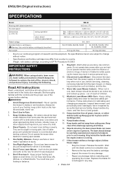
...power supply port 2. BH1420 - Using with USB device This charger works as an external power supply for USB device. 1. BH1233/C 14.4 V 12 - BH1433 Capacity (Ah) 2.0 2.0 3.3 3.3 Charging time (Minutes) 20 15 30 22 Voltage Number of cells Ni-MH Battery cartridge 9.6 V 8 BH9020A - Note: • The charger may not supply power...USB power supply port and USB device. 2. BH9033A - 12 V 10 - BL1850 45 Note: • It may lose by any possibility. • When not using or after charging, remove the USB cable and close the cover. 1. Open the cover of battery cartridge and maintenance ...
...power supply port 2. BH1420 - Using with USB device This charger works as an external power supply for USB device. 1. BH1233/C 14.4 V 12 - BH1433 Capacity (Ah) 2.0 2.0 3.3 3.3 Charging time (Minutes) 20 15 30 22 Voltage Number of cells Ni-MH Battery cartridge 9.6 V 8 BH9020A - Note: • The charger may not supply power...USB power supply port and USB device. 2. BH9033A - 12 V 10 - BL1850 45 Note: • It may lose by any possibility. • When not using or after charging, remove the USB cable and close the cover. 1. Open the cover of battery cartridge and maintenance ...
XML02 Instruction Manual
Page 2
... in use face or dust mask if operation is recommended when working order. 14. Stay Alert - Do not operate lawn mower when you are tired. Disconnect Lawn Mower - Disconnect the lawn mower from the power supply or remove the battery when not in moving parts. Keep blades sharp. 15. Wait until the blade comes to a complete stop. • Remove the key and the battery cartridge...
... in use face or dust mask if operation is recommended when working order. 14. Stay Alert - Do not operate lawn mower when you are tired. Disconnect Lawn Mower - Disconnect the lawn mower from the power supply or remove the battery when not in moving parts. Keep blades sharp. 15. Wait until the blade comes to a complete stop. • Remove the key and the battery cartridge...
XML02 Instruction Manual
Page 3
... stop before starting the motor. 30. Replace a worn grass basket with the charger specified by a safety device. 44. A charger that the blades coast after turn off and wait until it away from other metal objects, like paper clips, coins, keys, nails, screws or other similar obstruction, look down . Replace cracked or damaged blades immediately. 34. Do not mow on slopes. 18. Stop mower if anyone . Release switch lever...
... stop before starting the motor. 30. Replace a worn grass basket with the charger specified by a safety device. 44. A charger that the blades coast after turn off and wait until it away from other metal objects, like paper clips, coins, keys, nails, screws or other similar obstruction, look down . Replace cracked or damaged blades immediately. 34. Do not mow on slopes. 18. Stop mower if anyone . Release switch lever...

XML02 Instruction Manual
Page 4
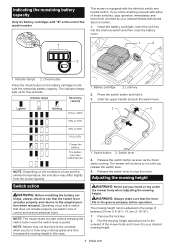
... DESCRIPTION Installing or removing battery cartridge CAUTION: Always switch off the tool before use it may result in a risk of the battery cartridge. If not, it for a long period (more than six months). CAUTION: Do not install the battery cartridge forcibly. Slide the battery cover locking lever and open the battery cover. 1 2 1. volts direct current no load speed revolutions or reciprocation per minute Important safety instructions for the Makita tool and charger. Do...
... DESCRIPTION Installing or removing battery cartridge CAUTION: Always switch off the tool before use it may result in a risk of the battery cartridge. If not, it for a long period (more than six months). CAUTION: Do not install the battery cartridge forcibly. Slide the battery cover locking lever and open the battery cover. 1 2 1. volts direct current no load speed revolutions or reciprocation per minute Important safety instructions for the Makita tool and charger. Do...

XML02 Instruction Manual
Page 5
... When the tool is overheated, the tool stops automatically. If the product does not operate even when the switches are operated, remove the batteries from the mower; 1. Insert the lock key in the place shown in the figure as far as it is operated in place with the locking lever. To remove the battery cartridge from the tool and charge the batteries. Then turn the tool off power to the motor to...
... When the tool is overheated, the tool stops automatically. If the product does not operate even when the switches are operated, remove the batteries from the mower; 1. Insert the lock key in the place shown in the figure as far as it is operated in place with the locking lever. To remove the battery cartridge from the tool and charge the batteries. Then turn the tool off power to the motor to...
XML02 Instruction Manual
Page 6
... the motor starts running. Increase the mowing height in the groove properly before operation. Battery cartridge 2. The battery may have them checked by your nearest Makita Authorized Service Center. 1. Release the switch lever to the outward of control and serious personal injury. The mowing height can lead to your hand or leg under the mower body when adjusting the mowing height. Switch button 2. Lock key 2. WARNING...
... the motor starts running. Increase the mowing height in the groove properly before operation. Battery cartridge 2. The battery may have them checked by your nearest Makita Authorized Service Center. 1. Release the switch lever to the outward of control and serious personal injury. The mowing height can lead to your hand or leg under the mower body when adjusting the mowing height. Switch button 2. Lock key 2. WARNING...
XML02 Instruction Manual
Page 7
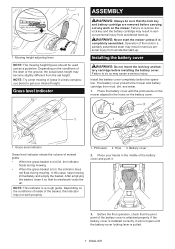
... lock key and battery cartridge are removed before carrying out any work properly. 1. NOTE: Try a test mowing of the battery cover and push it will not open until the battery cover locking lever is completely assembled. Failure to get your hands in serious personal injury from mud, dirt, and water. 1. Installing the battery cover WARNING: Do not insert the lock key and battery cartridge before the operation. The battery...
... lock key and battery cartridge are removed before carrying out any work properly. 1. NOTE: Try a test mowing of the battery cover and push it will not open until the battery cover locking lever is completely assembled. Failure to get your hands in serious personal injury from mud, dirt, and water. 1. Installing the battery cover WARNING: Do not insert the lock key and battery cartridge before the operation. The battery...

XML02 Instruction Manual
Page 8
... the upper side. 2. Clamping nut 2. To remove the mower blade, take the following steps. 1. Clamping screw 2. Holder Removing or installing the mower blade WARNING: Always remove the lock key and battery cartridge when removing or installing the blade. Mower blade 2. If the cord is damaged, the mower switch may cause a serious injury. To lock the blade rotation, insert a screwdriver or a similar tool into the grooves of upper handle and lower handle. Position the power supply cord as shown in...
... the upper side. 2. Clamping nut 2. To remove the mower blade, take the following steps. 1. Clamping screw 2. Holder Removing or installing the mower blade WARNING: Always remove the lock key and battery cartridge when removing or installing the blade. Mower blade 2. If the cord is damaged, the mower switch may cause a serious injury. To lock the blade rotation, insert a screwdriver or a similar tool into the grooves of upper handle and lower handle. Position the power supply cord as shown in...
XML02 Instruction Manual
Page 9
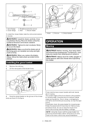
... grass basket on the motor, which may cause breakdown. 9 ENGLISH Before every periodical check, be sure to stop the mower then remove the lock key and the battery cartridge. Groove 3. 1 2 1 2 5 3 4 1. WARNING: Install the blade carefully. Inner flange 2. Lift the rear guard of the front wheels is the guideline for mowed grass. Firmly hold the lawn mower handle with both hands when mowing. The...
... grass basket on the motor, which may cause breakdown. 9 ENGLISH Before every periodical check, be sure to stop the mower then remove the lock key and the battery cartridge. Groove 3. 1 2 1 2 5 3 4 1. WARNING: Install the blade carefully. Inner flange 2. Lift the rear guard of the front wheels is the guideline for mowed grass. Firmly hold the lawn mower handle with both hands when mowing. The...

XML02 Instruction Manual
Page 10
.... Store the lock key in use gasoline, benzine, thinner, alcohol or the like. NOTE: Mowing long grass to a short length all in one go . Remove the lock key. 3. Damaged or missing parts should be sure that the handle does not fall down the handle forward. WARNING: Always be repaired or replaced. Clamping screw 2. Mowing a long-grass lawn Do not try to cut grass may...
.... Store the lock key in use gasoline, benzine, thinner, alcohol or the like. NOTE: Mowing long grass to a short length all in one go . Remove the lock key. 3. Damaged or missing parts should be sure that the handle does not fall down the handle forward. WARNING: Always be repaired or replaced. Clamping screw 2. Mowing a long-grass lawn Do not try to cut grass may...
XML02 Instruction Manual
Page 11
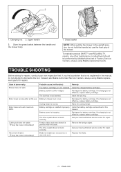
... SAFETY and RELIABILITY, repairs, any other maintenance or adjustment should be performed by Makita Authorized or Factory Service Centers, always using Makita replacement parts for repairs. Probable cause (malfunction) Two battery cartridges are not installed. Battery cartridge is not effective, replace battery cartridge. The drive system does not work correctly. Recharge the battery cartridge. If recharging is installed improperly. Ask your own inspection first. Remove the foreign object. Replace the blade. 11 ENGLISH Clamping nut...
... SAFETY and RELIABILITY, repairs, any other maintenance or adjustment should be performed by Makita Authorized or Factory Service Centers, always using Makita replacement parts for repairs. Probable cause (malfunction) Two battery cartridges are not installed. Battery cartridge is not effective, replace battery cartridge. The drive system does not work correctly. Recharge the battery cartridge. If recharging is installed improperly. Ask your own inspection first. Remove the foreign object. Replace the blade. 11 ENGLISH Clamping nut...

XML02 Instruction Manual
Page 12
... which vary from state to country. This Warranty gives you specific legal rights, and you . MAKITA LIMITED ONE YEAR WARRANTY Warranty Policy Every Makita tool is caused by others: • repairs are recommended for use with your local Makita Service Center. • Mower blade • Makita genuine battery and charger NOTE: Some items in the list may be free of defects from workmanship and materials for the...
... which vary from state to country. This Warranty gives you specific legal rights, and you . MAKITA LIMITED ONE YEAR WARRANTY Warranty Policy Every Makita tool is caused by others: • repairs are recommended for use with your local Makita Service Center. • Mower blade • Makita genuine battery and charger NOTE: Some items in the list may be free of defects from workmanship and materials for the...
XML02 Parts Breakdown
Page 3
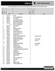
XML02 Tech Bulletin Part No. XML02 1 DECK, MOTOR, BLADE Products with multiple versions are listed in subsiding order with the newest version on top not indented. No. Section Fig. Description 11 273675-0 GRIP A 1 12 266459-3 TAPPING SCREW 5X25 2 13 453250-0 LOCK LEVER 1 14 453251-8 LOCK LEVER SUPPORT 1 15 233173-6 COMPRESSION SPRING 4 1 16 144077-6 REAR FLAP COMPLETE 1 16 141301-8 REAR FLAP COMPLETE 1 17...
XML02 Tech Bulletin Part No. XML02 1 DECK, MOTOR, BLADE Products with multiple versions are listed in subsiding order with the newest version on top not indented. No. Section Fig. Description 11 273675-0 GRIP A 1 12 266459-3 TAPPING SCREW 5X25 2 13 453250-0 LOCK LEVER 1 14 453251-8 LOCK LEVER SUPPORT 1 15 233173-6 COMPRESSION SPRING 4 1 16 144077-6 REAR FLAP COMPLETE 1 16 141301-8 REAR FLAP COMPLETE 1 17...
XML02 Parts Breakdown
Page 4
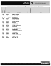
... top not indented. NUT M6 1 1 46 266326-2 TAPPING SCREW 4X18 1 1 47 267102-7 FLAT WASHER 4 1 1 48 231297-2 COMPRESSION SPRING 9 1 1 49 253808-3 FLAT WASHER 9 1 1 50 453252-6 CHANGE LEVER 1 1 51 453253-4 CHANGE LEVER COVER 1 1 120 424824-4 RUBBER SHEET 1 1 121 259015-6 STOP RING CS-3 2 Notes rev 1_02-13-18 4 Part No. Description 1 37 224444-2 INNER FLANGE 40 1 1 38 197761-2 BLADE 430 SET 1 1 38 196061-7 BLADE 430 SET 1 1 39 224445-0 OUTER...
... top not indented. NUT M6 1 1 46 266326-2 TAPPING SCREW 4X18 1 1 47 267102-7 FLAT WASHER 4 1 1 48 231297-2 COMPRESSION SPRING 9 1 1 49 253808-3 FLAT WASHER 9 1 1 50 453252-6 CHANGE LEVER 1 1 51 453253-4 CHANGE LEVER COVER 1 1 120 424824-4 RUBBER SHEET 1 1 121 259015-6 STOP RING CS-3 2 Notes rev 1_02-13-18 4 Part No. Description 1 37 224444-2 INNER FLANGE 40 1 1 38 197761-2 BLADE 430 SET 1 1 38 196061-7 BLADE 430 SET 1 1 39 224445-0 OUTER...

XML02 Parts Breakdown
Page 6
No. XML02 Tech Bulletin Part No. LOCK NUT M5-8 1 2 66 941101-4 FLAT WASHER 5 1 2 67 346543-1 CONNECTING ROD 1 2 68 231875-8 TENSION SPRING 16 1 2 69 941101-4 FLAT WASHER 5 1 2 70 252103-8 HEX. LOCK NUT M5-8 1 2 71 453240-3 FRONT WHEEL CAP 1 2 72 252145-2 COLLARED HEX NUT M8 1 2 73 214067-4 PLANE BEARING 10 1 2 74 453242-9 FRONT WHEEL 1 2 75 211066-7 BALL BEARING 6200ZZ 1 2 75 210070-3 BALL BEARING 6200ZZ...
No. XML02 Tech Bulletin Part No. LOCK NUT M5-8 1 2 66 941101-4 FLAT WASHER 5 1 2 67 346543-1 CONNECTING ROD 1 2 68 231875-8 TENSION SPRING 16 1 2 69 941101-4 FLAT WASHER 5 1 2 70 252103-8 HEX. LOCK NUT M5-8 1 2 71 453240-3 FRONT WHEEL CAP 1 2 72 252145-2 COLLARED HEX NUT M8 1 2 73 214067-4 PLANE BEARING 10 1 2 74 453242-9 FRONT WHEEL 1 2 75 211066-7 BALL BEARING 6200ZZ 1 2 75 210070-3 BALL BEARING 6200ZZ...
XML02 Parts Breakdown
Page 7
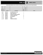
Description 2 82 252145-2 COLLARED HEX NUT M8 1 2 83 453240-3 FRONT WHEEL CAP 1 2 115 453257-6 PROTECTIVE SHIELD HOLDER 1 2 116 266326-2 TAPPING SCREW 4X18 2 2 117 961013-5 STOP RING E-7 2 2 118 256872-3 ROD 8 1 2 119 424481-8 PROTECTIVE SHIELD 1 Notes rev 1_02-13-18 7 Part No. XML02 Tech Bulletin 2 XML02 WHEELS, AXLES Products with multiple versions are listed in subsiding order with the newest version on top not indented. No. Section Fig.
Description 2 82 252145-2 COLLARED HEX NUT M8 1 2 83 453240-3 FRONT WHEEL CAP 1 2 115 453257-6 PROTECTIVE SHIELD HOLDER 1 2 116 266326-2 TAPPING SCREW 4X18 2 2 117 961013-5 STOP RING E-7 2 2 118 256872-3 ROD 8 1 2 119 424481-8 PROTECTIVE SHIELD 1 Notes rev 1_02-13-18 7 Part No. XML02 Tech Bulletin 2 XML02 WHEELS, AXLES Products with multiple versions are listed in subsiding order with the newest version on top not indented. No. Section Fig.

XML02 Parts Breakdown
Page 9
...-8 SWITCH LEVER 1 SWITCH LEVER CASE 1 SWITCH LEVER CASE COVER 1 TAPPING SCREW 4X18 1 TAPPING SCREW 4X18 4 SWITCH BOX COVER COMPLETE K 1 PAN HEAD SCREW M4X20 1 LEVER 1 TENSION SPRING 9 1 SWITCH BUTTON 1 COMPRESSION SPRING 6 1 SWITCH TG72BD-6 1 SWITCH BOX 1 STRAIN RELIEF 1 TAPPING SCREW 4X25 2 UPPER PIPE COMPLETE 1 POWER SUPPLY CORD 1 CUP H. XML02 Tech Bulletin 3 XML02 HANDLES Products with multiple versions are listed in subsiding order with the newest version on top not indented. Part No. SQUARE NECK BOLT M6X50 1 LOWER PIPE 1 HOLDER 2 THUMB SCREW...
...-8 SWITCH LEVER 1 SWITCH LEVER CASE 1 SWITCH LEVER CASE COVER 1 TAPPING SCREW 4X18 1 TAPPING SCREW 4X18 4 SWITCH BOX COVER COMPLETE K 1 PAN HEAD SCREW M4X20 1 LEVER 1 TENSION SPRING 9 1 SWITCH BUTTON 1 COMPRESSION SPRING 6 1 SWITCH TG72BD-6 1 SWITCH BOX 1 STRAIN RELIEF 1 TAPPING SCREW 4X25 2 UPPER PIPE COMPLETE 1 POWER SUPPLY CORD 1 CUP H. XML02 Tech Bulletin 3 XML02 HANDLES Products with multiple versions are listed in subsiding order with the newest version on top not indented. Part No. SQUARE NECK BOLT M6X50 1 LOWER PIPE 1 HOLDER 2 THUMB SCREW...

XML02 Parts Breakdown
Page 11
Part No. 4 109 4 110 4 110 4 111 4 112 4 113 4 114 4 A01 4 E01 456355-5 126621-1 123526-6 266326-2 326118-2 267438-4 266326-2 782210-8 632D01-0 Description INDICATOR M REAR BAG ASS'Y MA REAR BAG ASS'Y MA TAPPING SCREW 4X18 REAR BAG ROD FLAT WASHER 5 TAPPING SCREW 4X18 SOCKET WRENCH 17 FUSE UNIT Notes 1 1 Includes #109 1 3 1 2 2 1 Not pictured 1 Not pictured rev 1_02-13-18 11 No. XML02 Tech Bulletin 4 XML02 BAGGER, FRAME Products with multiple versions are listed in subsiding order with the newest version on top not indented. Section Fig.
Part No. 4 109 4 110 4 110 4 111 4 112 4 113 4 114 4 A01 4 E01 456355-5 126621-1 123526-6 266326-2 326118-2 267438-4 266326-2 782210-8 632D01-0 Description INDICATOR M REAR BAG ASS'Y MA REAR BAG ASS'Y MA TAPPING SCREW 4X18 REAR BAG ROD FLAT WASHER 5 TAPPING SCREW 4X18 SOCKET WRENCH 17 FUSE UNIT Notes 1 1 Includes #109 1 3 1 2 2 1 Not pictured 1 Not pictured rev 1_02-13-18 11 No. XML02 Tech Bulletin 4 XML02 BAGGER, FRAME Products with multiple versions are listed in subsiding order with the newest version on top not indented. Section Fig.


