
Owners Manual
Page 4
... begins to bind during all times, especially during operation. NEVER use tool where operator positioning would be secured firmly against the turn base and guide fence with a vise during a cutting operation, do not continue to fasten the saw blade. 6. Be aware that could indicate poor installation or a poorly balanced blade. 24...
... begins to bind during all times, especially during operation. NEVER use tool where operator positioning would be secured firmly against the turn base and guide fence with a vise during a cutting operation, do not continue to fasten the saw blade. 6. Be aware that could indicate poor installation or a poorly balanced blade. 24...
Owners Manual
Page 7
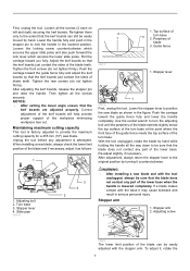
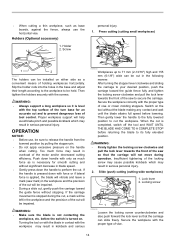
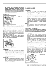
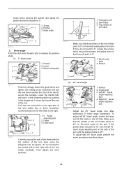
... handle is attempted. Unplug the tool before any part of the blade teeth. Turn base 3. Slide pipe 009518 3 4 2 2 1 009737 1. Guide fence 1. Use the socket wrench to turn the adjusting bolt until the periphery of the blade extends slightly below the top surface of the turn base... to the original position by hand. Stopper lever 4. Periphery of the workpiece minimizing workpiece tear out. Push the carriage toward the guide fence fully and adjust the kerf boards so that the kerf boards just contact the sides of the turn base 2. After adjustment, always return...
... handle is attempted. Unplug the tool before any part of the blade teeth. Turn base 3. Slide pipe 009518 3 4 2 2 1 009737 1. Guide fence 1. Use the socket wrench to turn the adjusting bolt until the periphery of the blade extends slightly below the top surface of the turn base... to the original position by hand. Stopper lever 4. Periphery of the workpiece minimizing workpiece tear out. Push the carriage toward the guide fence fully and adjust the kerf boards so that the kerf boards just contact the sides of the turn base 2. After adjustment, always return...

Owners Manual
Page 10
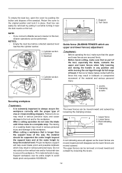
... socket wrench is stored as shown in overtightening or insufficient tightening of guide fence in the stopper pin. 1 1. Hex bolt 4. Blade guard 4 009497 10 NOTE: • Use wood facing... against the guide fence when aligning the cutting line with the laser line. ASSEMBLY WARNING: • Always be sure ...shifted to the applications of the tool may result in serious personal injury. • Use only the Makita socket wrench provided to install or remove the blade.Failure to use the socket wrench to switch off ...
... socket wrench is stored as shown in overtightening or insufficient tightening of guide fence in the stopper pin. 1 1. Hex bolt 4. Blade guard 4 009497 10 NOTE: • Use wood facing... against the guide fence when aligning the cutting line with the laser line. ASSEMBLY WARNING: • Always be sure ...shifted to the applications of the tool may result in serious personal injury. • Use only the Makita socket wrench provided to install or remove the blade.Failure to use the socket wrench to switch off ...
Owners Manual
Page 12
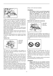
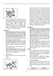
... Dust box 3. Cylinder section 2. Turn base NOTE: • If you connect a Makita vacuum cleaner to this may result in kickback or unexpected movement of vise or crown molding stoppers. Lower fence 3. Upper fence 2. To empty the dust box, open the cover by pulling it out while turning ...it near the dust nozzle on the vertical vise and/or horizontal vise to secure the workpiece. The upper fences can be removed or moved inward and outward by loosening the clamping screws. 1 3 2 1. Clamping screws 2 010591 Securing workpiece WARNING:...
... Dust box 3. Cylinder section 2. Turn base NOTE: • If you connect a Makita vacuum cleaner to this may result in kickback or unexpected movement of vise or crown molding stoppers. Lower fence 3. Upper fence 2. To empty the dust box, open the cover by pulling it out while turning ...it near the dust nozzle on the vertical vise and/or horizontal vise to secure the workpiece. The upper fences can be removed or moved inward and outward by loosening the clamping screws. 1 3 2 1. Clamping screws 2 010591 Securing workpiece WARNING:...
Owners Manual
Page 13
...the original position and return it firmly by tightening the levers. When bevel-cutting operations are complete, don't forget to return the upper fences to provide maximum workpiece support, and make a dry run with the vise during the cutting operation causing possible damage to the blade, ...base. Horizontal vise (optional accessory) 1. Insert the vise rod into the hole in serious personal injury. Press the workpiece flat against the fence the material may move during all operations. Turning the vise knob to 90° counterclockwise allows the vise knob to secure the workpiece. ...
...the original position and return it firmly by tightening the levers. When bevel-cutting operations are complete, don't forget to return the upper fences to provide maximum workpiece support, and make a dry run with the vise during the cutting operation causing possible damage to the blade, ...base. Horizontal vise (optional accessory) 1. Insert the vise rod into the hole in serious personal injury. Press the workpiece flat against the fence the material may move during all operations. Turning the vise knob to 90° counterclockwise allows the vise knob to secure the workpiece. ...
Owners Manual
Page 14
... operation. Holders (Optional accessory) 1. If the carriage movement is necessary for an accurate cut , gently push the carriage toward the guide fence without the blade making any contact and wait until the blade attains full speed before returning the blade to your desired position, push the ...carriage toward the guide fence fully and tighten the locking screw clockwise and pull the lock lever towards the front of the cut . Locking screw 2 1 009496 Loosen...
... operation. Holders (Optional accessory) 1. If the carriage movement is necessary for an accurate cut , gently push the carriage toward the guide fence without the blade making any contact and wait until the blade attains full speed before returning the blade to your desired position, push the ...carriage toward the guide fence fully and tighten the locking screw clockwise and pull the lock lever towards the front of the cut . Locking screw 2 1 009496 Loosen...
Owners Manual
Page 15
... the handle all the way back toward the operator. Compound cutting can be impaired. • Before bevel-cutting, an adjustment of the upper fence and lower fence maybe required. WARNING: • Whenever performing a slide cut, first pull the carriage full towards you fully. Secure the workpiece with the blade...the blade may come to the actual blade path while cutting and contact with the blade and PUSH THE CARRIAGE TOWARD THE GUIDE FENCE TO CUT THE WORKPIECE. Then gently lower the handle to the fully lowered position while applying pressure in parallel with the blade will...
... the handle all the way back toward the operator. Compound cutting can be impaired. • Before bevel-cutting, an adjustment of the upper fence and lower fence maybe required. WARNING: • Whenever performing a slide cut, first pull the carriage full towards you fully. Secure the workpiece with the blade...the blade may come to the actual blade path while cutting and contact with the blade and PUSH THE CARRIAGE TOWARD THE GUIDE FENCE TO CUT THE WORKPIECE. Then gently lower the handle to the fully lowered position while applying pressure in parallel with the blade will...
Owners Manual
Page 16
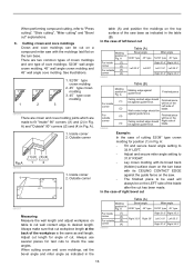
... When cutting crown and cove moldings, set the bevel angle and miter angle as indicated in Fig. A). 1. A Molding edge against guide fence Finished piece For inside (1) Ceiling contact edge should be For outside (3) corner (4) 006363 Miter angle 52/38° type 45° ...; type For inside (1) corner (2) Right 33.9° Right 30° For outside against guide fence. (3) Finished piece will be against guide fence. Finished piece will always be against the guide fence on the saw. • The finished piece to be used will be cut " explanations. 6....
... When cutting crown and cove moldings, set the bevel angle and miter angle as indicated in Fig. A). 1. A Molding edge against guide fence Finished piece For inside (1) Ceiling contact edge should be For outside (3) corner (4) 006363 Miter angle 52/38° type 45° ...; type For inside (1) corner (2) Right 33.9° Right 30° For outside against guide fence. (3) Finished piece will be against guide fence. Finished piece will always be against the guide fence on the saw. • The finished piece to be used will be cut " explanations. 6....

Owners Manual
Page 17
... 31.6° RIGHT. • Lay crown molding with its broad back (hidden) surface down on the turn base with its WALL CONTACT EDGE against guide fence. (3) Finished piece will be on the corner Right side of the blade after the cut has been made. 17 Table (B) Molding position in Fig. A ...Molding edge against guide fence Finished piece For inside (1) Wall contact edge should For outside be against the guide fence on the saw. • The finished piece to be used will always be on the RIGHT side of...
... 31.6° RIGHT. • Lay crown molding with its broad back (hidden) surface down on the turn base with its WALL CONTACT EDGE against guide fence. (3) Finished piece will be on the corner Right side of the blade after the cut has been made. 17 Table (B) Molding position in Fig. A ...Molding edge against guide fence Finished piece For inside (1) Wall contact edge should For outside be against the guide fence on the saw. • The finished piece to be used will always be on the RIGHT side of...
Owners Manual
Page 20
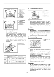
...screws to perform this type of the blade. WARNING: • Never attempt to make a groove cut thick or round aluminum extrusions. Guide fence 1 2. Vise 2 3. Use a cutting lubricant when cutting the aluminum extrusion to the size of the aluminum material on the blade. ...blade 2 009520 Table (C) Position in the figure. Spacer block 3 4. Crown molding 7. 12 3 009521 12 3 1. Turn base 1. Guide fence 1 2. Spacer block 009523 When securing aluminum extrusions, use spacer blocks or pieces of scrap as follows: Adjust the lower limit position of the...
...screws to perform this type of the blade. WARNING: • Never attempt to make a groove cut thick or round aluminum extrusions. Guide fence 1 2. Vise 2 3. Use a cutting lubricant when cutting the aluminum extrusion to the size of the aluminum material on the blade. ...blade 2 009520 Table (C) Position in the figure. Spacer block 3 4. Crown molding 7. 12 3 009521 12 3 1. Turn base 1. Guide fence 1 2. Spacer block 009523 When securing aluminum extrusions, use spacer blocks or pieces of scrap as follows: Adjust the lower limit position of the...
Owners Manual
Page 21
...Adjusting the cutting angle This tool is sharp and clean for the best and safest performance. Miter angle Push the carriage toward the guide fence and tighten the locking screw clockwise and pull the lock lever towards the front of the saw to the section titled "Slide lock adjustment... before carrying the tool. Carry the tool by pushing in the stopper pin. Failure to 0°.) Loosen the hex sockets bolts securing the guide fence using a triangular rule, try-square, etc. Discoloration, deformation or cracks may cause kickback and result in a serious personal injury. Turn the grip...
...Adjusting the cutting angle This tool is sharp and clean for the best and safest performance. Miter angle Push the carriage toward the guide fence and tighten the locking screw clockwise and pull the lock lever towards the front of the saw to the section titled "Slide lock adjustment... before carrying the tool. Carry the tool by pushing in the stopper pin. Failure to 0°.) Loosen the hex sockets bolts securing the guide fence using a triangular rule, try-square, etc. Discoloration, deformation or cracks may cause kickback and result in a serious personal injury. Turn the grip...
Owners Manual
Page 22
... the same procedure described above. 22 Top surface of the arm holder clockwise. Bevel scale plate 2. Pointer 3 009512 009511 Push the carriage toward the guide fence and tighten the locking screw clockwise and pull the lock lever towards the front of the saw to 45°.
... the same procedure described above. 22 Top surface of the arm holder clockwise. Bevel scale plate 2. Pointer 3 009512 009511 Push the carriage toward the guide fence and tighten the locking screw clockwise and pull the lock lever towards the front of the saw to 45°.

Parts Breakdown
Page 4
... 130 941102-2 F. SCREW, 5740NB 93 224428-0 INNER FLANGE 46, LS1016 94 224429-8 OUTER FLANGE 46, LS1016 95 265405-3 H.F.H. WASHER 6, 6012HDW 134 158970-8 UPPER FENCE R CPL., LS1016 135 346058-8 GUIDE PLATE, LS1016 136 318415-0 LOWER FENCE R, LS1016 136 318596-0 LOWER FENCE R, LS1016 137 265783-1 THUMB SCREW M6X18, LS1016 138 318411-8 GUIDE FENCE, LS1016 138 318411-8 GUIDE FENCE, LS1016 139 922443-5 HSH BOLT M8X25 WITH WR...
... 130 941102-2 F. SCREW, 5740NB 93 224428-0 INNER FLANGE 46, LS1016 94 224429-8 OUTER FLANGE 46, LS1016 95 265405-3 H.F.H. WASHER 6, 6012HDW 134 158970-8 UPPER FENCE R CPL., LS1016 135 346058-8 GUIDE PLATE, LS1016 136 318415-0 LOWER FENCE R, LS1016 136 318596-0 LOWER FENCE R, LS1016 137 265783-1 THUMB SCREW M6X18, LS1016 138 318411-8 GUIDE FENCE, LS1016 138 318411-8 GUIDE FENCE, LS1016 139 922443-5 HSH BOLT M8X25 WITH WR...

Parts Breakdown
Page 5
... 232250-1 LEAF SPRING, LS1016 1 197 325646-4 CENTER SHAFT, LS1016 1 198 451039-0 POSITION PLATE, LS1016 1 199 451070-6 ARM HOLDER COVER, LS1016 1 200 266034-5 TAPPING SCREW 4X16, 9524NB 1 201 158967-7 SQUARE ROD CPL., LS1016 1 202 925251-3 HEX. Parts Breakdown LS1016 142 265783-1 THUMB SCREW M6X18, LS1016 1 143 318413-4 LOWER FENCE L, LS1016L 1 143 318595-2 LOWER FENCE L, LS1016 1 144 158969-3 UPPER FENCE L CPL., LS1016 1 145 346049...
... 232250-1 LEAF SPRING, LS1016 1 197 325646-4 CENTER SHAFT, LS1016 1 198 451039-0 POSITION PLATE, LS1016 1 199 451070-6 ARM HOLDER COVER, LS1016 1 200 266034-5 TAPPING SCREW 4X16, 9524NB 1 201 158967-7 SQUARE ROD CPL., LS1016 1 202 925251-3 HEX. Parts Breakdown LS1016 142 265783-1 THUMB SCREW M6X18, LS1016 1 143 318413-4 LOWER FENCE L, LS1016L 1 143 318595-2 LOWER FENCE L, LS1016 1 144 158969-3 UPPER FENCE L CPL., LS1016 1 145 346049...

Flyer (English)
Page 1
... bearings and a patented 4-steel rail sliding system deliver dead-on cuts PORTABILITY The most compact design in its class for easy jobsite portability VERSATILITY Models LS1016 / LS1016L 4-3/4" tall dual sliding fence system features upper and lower fence adjustments for more precise cuts LARGE CUTTING CAPACITY makitatools.com
... bearings and a patented 4-steel rail sliding system deliver dead-on cuts PORTABILITY The most compact design in its class for easy jobsite portability VERSATILITY Models LS1016 / LS1016L 4-3/4" tall dual sliding fence system features upper and lower fence adjustments for more precise cuts LARGE CUTTING CAPACITY makitatools.com

Flyer (English)
Page 2
... micro-adjustments for precise "left-of-blade" or "right-of-blade" cutting (LS1016L only) LS1016/LS1016L LS1016L LS1016/LS1016L LS1016 SPECIFICATIONS OPTIONAL ACCESSORIES Blade diameter 10" Arbor 5/8" Capacities: Bevel range L/R Miter range L/R Cutting ...60 80 40 60 80 70 Part # A-94758 A-94764 A-94770 A-93669 A-93675 A-93681 792303-3 Makita offers a wide variety of MITER SAW accessories. NTF-0209-1 MA-0167-09 For more precise miter ... cutting I Exclusive 4-3/4" dual sliding fence system features upper and lower fence adjustments for more information, call 1-800-4MAKITA.
... micro-adjustments for precise "left-of-blade" or "right-of-blade" cutting (LS1016L only) LS1016/LS1016L LS1016L LS1016/LS1016L LS1016 SPECIFICATIONS OPTIONAL ACCESSORIES Blade diameter 10" Arbor 5/8" Capacities: Bevel range L/R Miter range L/R Cutting ...60 80 40 60 80 70 Part # A-94758 A-94764 A-94770 A-93669 A-93675 A-93681 792303-3 Makita offers a wide variety of MITER SAW accessories. NTF-0209-1 MA-0167-09 For more precise miter ... cutting I Exclusive 4-3/4" dual sliding fence system features upper and lower fence adjustments for more information, call 1-800-4MAKITA.

Technical Reference
Page 1
...consistent pursuit of LS1013 series models, H featuring DXT (Deep eXact cutting Technology) achieved by employing: Double sliding mechanism Double sliding guide fence Quick and accurate miter angle lock, etc Dimensions: mm (") Length (L) 718 (28-1/4) Width (W) 640 (25-1/4) Height (H) 671... (26-1/2) LS1016L additionally features laser marker for the cutting capacities. LS1016 LS1016L No load speed: min-1 = rpm 3,200 Saw blade: Diameter mm (") Hole diameter 250 (9-7/8) - 260 (10-1/4) European countries: 30, ...
...consistent pursuit of LS1013 series models, H featuring DXT (Deep eXact cutting Technology) achieved by employing: Double sliding mechanism Double sliding guide fence Quick and accurate miter angle lock, etc Dimensions: mm (") Length (L) 718 (28-1/4) Width (W) 640 (25-1/4) Height (H) 671... (26-1/2) LS1016L additionally features laser marker for the cutting capacities. LS1016 LS1016L No load speed: min-1 = rpm 3,200 Saw blade: Diameter mm (") Hole diameter 250 (9-7/8) - 260 (10-1/4) European countries: 30, ...

Technical Reference
Page 2
... cut Vertical cut Horizontal cut Capacity: mm (") 168** 248 120 305 *Diagonal cut is to cut a crown molding that is held tilted against the guide fence using L Crown molding stopper. **The capacity of crown molding diagonal cut is the length L shown in the drawing on right. 45 degrees right 29 x 305...
... cut Vertical cut Horizontal cut Capacity: mm (") 168** 248 120 305 *Diagonal cut is to cut a crown molding that is held tilted against the guide fence using L Crown molding stopper. **The capacity of crown molding diagonal cut is the length L shown in the drawing on right. 45 degrees right 29 x 305...

Technical Reference
Page 4
... Spring 45 Loop portion 102 Center washer Portion where Center cover contacts 103 Center plate Portion where Center cover contacts 136 143 Lower fence a. Repair [2] LUBRICATIONS (cont.) Apply Makita grease SG.No.00 to the following portions designated with Front arm Drum portion Drum portion Whole portion Fig. 2 Fig. 3 Safety ...B Arm section 152 Stopper pin 97 Knob 20 63 103 Center cover 149 Safety cover A complete Torsion spring 35 Front arm 150 Fig. 4 Lower fence L, R Upper fence 136 143 138 143 138 a b Pin 4 P 4/ 37 Item No. Portion where Pin 4 contacts 138 Guide...
... Spring 45 Loop portion 102 Center washer Portion where Center cover contacts 103 Center plate Portion where Center cover contacts 136 143 Lower fence a. Repair [2] LUBRICATIONS (cont.) Apply Makita grease SG.No.00 to the following portions designated with Front arm Drum portion Drum portion Whole portion Fig. 2 Fig. 3 Safety ...B Arm section 152 Stopper pin 97 Knob 20 63 103 Center cover 149 Safety cover A complete Torsion spring 35 Front arm 150 Fig. 4 Lower fence L, R Upper fence 136 143 138 143 138 a b Pin 4 P 4/ 37 Item No. Portion where Pin 4 contacts 138 Guide...

Technical Reference
Page 17
... illustrated in Fig. 37. (2) Removing M8x45 Hex bolt, separate Turn base section from Base by unscrewing 4x12 Tapping screw (3pcs.) Lower fence (2pcs.) Guide fence Grip 50 Fig. 38 Remove M8x45 Hex bolt with Socket wrench 13. ASSEMBLING Assemble Turn base section as illustrated in Fig. 38. Fig...Hex bolt Flat washer 8 Base Miter scale plate Lock lever While pressing down Lock lever, fit Turn base section to Base. Remove Upper fence, Lower fence, Guide fence and Kerf board. Turn base section has to the direction designated with M8x45 Hex bolt so that it stops. Turn Base, Base P...
... illustrated in Fig. 37. (2) Removing M8x45 Hex bolt, separate Turn base section from Base by unscrewing 4x12 Tapping screw (3pcs.) Lower fence (2pcs.) Guide fence Grip 50 Fig. 38 Remove M8x45 Hex bolt with Socket wrench 13. ASSEMBLING Assemble Turn base section as illustrated in Fig. 38. Fig...Hex bolt Flat washer 8 Base Miter scale plate Lock lever While pressing down Lock lever, fit Turn base section to Base. Remove Upper fence, Lower fence, Guide fence and Kerf board. Turn base section has to the direction designated with M8x45 Hex bolt so that it stops. Turn Base, Base P...
