Owners Manual
Page 5
Complies with 21CFR 1040.10 and 1040.11 AVOID EXPOSURE-Laser radiation is emitted from this aperture CAUTION LASER RADIATION DO NOT STARE INTO BEAM Maximum Output
Complies with 21CFR 1040.10 and 1040.11 AVOID EXPOSURE-Laser radiation is emitted from this aperture CAUTION LASER RADIATION DO NOT STARE INTO BEAM Maximum Output

Owners Manual
Page 8
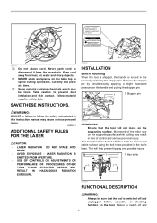
..., tilt the carriage to raise the handle fully. Push the latch lever forward as explained in the figure fully while supporting the weight of the saw blade can be sure to release the pressure on the bevel scale. When tilting the carriage to the right, tilt the carriage to lock the....9 ° angle to secure the arm. 4 3 1. When you have moved the grip to the position where the pointer points to the desired angle on the miter scale, turn it stops. Then tighten the lever clockwise firmly to the base surface. Adjusting the bevel angle To adjust the bevel angle, loosen the...
..., tilt the carriage to raise the handle fully. Push the latch lever forward as explained in the figure fully while supporting the weight of the saw blade can be sure to release the pressure on the bevel scale. When tilting the carriage to the right, tilt the carriage to lock the....9 ° angle to secure the arm. 4 3 1. When you have moved the grip to the position where the pointer points to the desired angle on the miter scale, turn it stops. Then tighten the lever clockwise firmly to the base surface. Adjusting the bevel angle To adjust the bevel angle, loosen the...

Owners Manual
Page 10
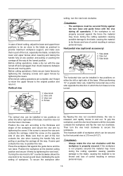
...009483 To remove the blade, use the wrench may result in serious personal injury. • Use only the Makita socket wrench provided to install or remove the blade.Failure to use the socket wrench to switch off and unplug ... pulled out of the blade (cutting position). B) When you obtain the correct size on the tool. Installing or removing saw blade WARNING: • Always be sure that the tool is less direct sunlight. ASSEMBLY WARNING: • Always be ... insufficient tightening of guide fence in compound cutting (bevel angle 45 degrees and miter angle right 45 degrees).
...009483 To remove the blade, use the wrench may result in serious personal injury. • Use only the Makita socket wrench provided to install or remove the blade.Failure to use the socket wrench to switch off and unplug ... pulled out of the blade (cutting position). B) When you obtain the correct size on the tool. Installing or removing saw blade WARNING: • Always be sure that the tool is less direct sunlight. ASSEMBLY WARNING: • Always be ... insufficient tightening of guide fence in compound cutting (bevel angle 45 degrees and miter angle right 45 degrees).
Owners Manual
Page 13
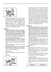
... clockwise to the original position and return it firmly by tightening the levers. Horizontal vise (optional accessory) 1. When performing 15° or greater miter cuts, install the horizontal vise on either the left or right side of the base. If some part contacts the vise, re-position the vise... the workpiece and flip the vise nut clockwise. Make sure that no part of workpiece which the turn base and guide fence with the saw turned off and unplugged, then check clearance between fences and moving parts. The maximum width of the tool contacts the vise when lowering the...
... clockwise to the original position and return it firmly by tightening the levers. Horizontal vise (optional accessory) 1. When performing 15° or greater miter cuts, install the horizontal vise on either the left or right side of the base. If some part contacts the vise, re-position the vise... the workpiece and flip the vise nut clockwise. Make sure that no part of workpiece which the turn base and guide fence with the saw turned off and unplugged, then check clearance between fences and moving parts. The maximum width of the tool contacts the vise when lowering the...
Owners Manual
Page 15
... all the way back toward the operator. During a bevel cut the piece cut . Bevel cut , before returning the blade to fragment which a miter angle is changed during the cutting operation may result. • Never attempt to secure the selected bevel angle safely. WARNING: • After setting ...the blade for a bevel cut Loosen the lever and tilt the saw blade to set the bevel angle (Refer to the section titled "Guide fence adjustment". 5. Switch on the tool without the carriage pulled fully toward...
... all the way back toward the operator. During a bevel cut the piece cut . Bevel cut , before returning the blade to fragment which a miter angle is changed during the cutting operation may result. • Never attempt to secure the selected bevel angle safely. WARNING: • After setting ...the blade for a bevel cut Loosen the lever and tilt the saw blade to set the bevel angle (Refer to the section titled "Guide fence adjustment". 5. Switch on the tool without the carriage pulled fully toward...
Owners Manual
Page 16
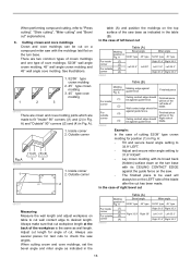
...be cut . Wall contact edge should be For outside against guide fence. (3) Finished piece will be against the guide fence on a compound miter saw angles. In the case of the blade after the cut Table (A) Molding Bevel angle position in Fig. See illustrations. 1. 52/38 &#...90° corners ((1) and (2) in Fig. A: • Tilt and secure bevel angle setting to 33.9° LEFT. • Adjust and secure miter angle setting to cut " explanations. 6. Adjust cut length for position (1) in the table (B). Cutting crown and cove moldings Crown and cove moldings can...
...be cut . Wall contact edge should be For outside against guide fence. (3) Finished piece will be against the guide fence on a compound miter saw angles. In the case of the blade after the cut Table (A) Molding Bevel angle position in Fig. See illustrations. 1. 52/38 &#...90° corners ((1) and (2) in Fig. A: • Tilt and secure bevel angle setting to 33.9° LEFT. • Adjust and secure miter angle setting to cut " explanations. 6. Adjust cut length for position (1) in the table (B). Cutting crown and cove moldings Crown and cove moldings can...

Owners Manual
Page 17
...006364 Example: In the case of against guide fence. A: • Tilt and secure bevel angle setting to 33.9° RIGHT. • Adjust and secure miter angle setting to 31.6° RIGHT. • Lay crown molding with its broad back (hidden) surface down on the turn base with its WALL CONTACT... Finished piece For inside (1) Wall contact edge should For outside be against guide fence. (3) Finished piece will be against the guide fence on the saw. • The finished piece to be used will always be on the corner (4) Wall contact edge should be on the RIGHT side of (2) blade...
...006364 Example: In the case of against guide fence. A: • Tilt and secure bevel angle setting to 33.9° RIGHT. • Adjust and secure miter angle setting to 31.6° RIGHT. • Lay crown molding with its broad back (hidden) surface down on the turn base with its WALL CONTACT... Finished piece For inside (1) Wall contact edge should For outside be against guide fence. (3) Finished piece will be against the guide fence on the saw. • The finished piece to be used will always be on the corner (4) Wall contact edge should be on the RIGHT side of (2) blade...

Owners Manual
Page 18
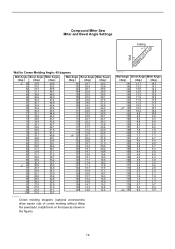
Compound Miter Saw Miter and Bevel Angle Settings Ceiling 52° 38° Wall Wall to Crown Molding Angle: 52/38 degrees Wall Angle Bevel Angle Miter Angle (deg.) (deg.) (deg.) 60 43.0 46.8 61 42... 29.0 97 31.5 28.6 98 31.1 28.2 99 30.8 27.7 100 30.4 27.3 Wall Angle Bevel Angle Miter Angle (deg.) (deg.) (deg.) 101 30.1 26.9 102 29.7 26.5 103 29.4 26.1 104 29.0 25...137 16.8 13.6 138 16.4 13.3 139 16.0 13.0 140 15.6 12.8 EN0002-1 000031 Wall Angle Bevel Angle Miter Angle (deg.) (deg.) (deg.) 141 15.3 12.3 142 14.9 12.0 143 14.5 11.6 144 14.1 11...
Compound Miter Saw Miter and Bevel Angle Settings Ceiling 52° 38° Wall Wall to Crown Molding Angle: 52/38 degrees Wall Angle Bevel Angle Miter Angle (deg.) (deg.) (deg.) 60 43.0 46.8 61 42... 29.0 97 31.5 28.6 98 31.1 28.2 99 30.8 27.7 100 30.4 27.3 Wall Angle Bevel Angle Miter Angle (deg.) (deg.) (deg.) 101 30.1 26.9 102 29.7 26.5 103 29.4 26.1 104 29.0 25...137 16.8 13.6 138 16.4 13.3 139 16.0 13.0 140 15.6 12.8 EN0002-1 000031 Wall Angle Bevel Angle Miter Angle (deg.) (deg.) (deg.) 141 15.3 12.3 142 14.9 12.0 143 14.5 11.6 144 14.1 11...
Owners Manual
Page 19
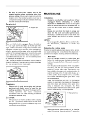
Compound Miter Saw Miter and Bevel Angle Settings Ceiling 45° 45° Wall Wall to Crown Molding Angle: 45 degrees Wall Angle Bevel Angle Miter Angle (deg.) (deg.) (deg.) 60 37.8 50.8 61 37.5 50.2 62 37.3 49.6 63 37.1 49.1 64 36.8 48.5 65 36.6 48.0 66 36.4 ... 14.0 14.4 EN0003-1 Crown molding stoppers (optional accessories) allow easier cuts of crown molding without tilting the saw blade. Install them on the base as shown in the figures. 000032 Wall Angle Bevel Angle Miter Angle (deg.) (deg.) (deg.) 141 13.7 14.1 142 13.3 13.7 143 13.0 13.3 144 12.6 12...
Compound Miter Saw Miter and Bevel Angle Settings Ceiling 45° 45° Wall Wall to Crown Molding Angle: 45 degrees Wall Angle Bevel Angle Miter Angle (deg.) (deg.) (deg.) 60 37.8 50.8 61 37.5 50.2 62 37.3 49.6 63 37.1 49.1 64 36.8 48.5 65 36.6 48.0 66 36.4 ... 14.0 14.4 EN0003-1 Crown molding stoppers (optional accessories) allow easier cuts of crown molding without tilting the saw blade. Install them on the base as shown in the figures. 000032 Wall Angle Bevel Angle Miter Angle (deg.) (deg.) (deg.) 141 13.7 14.1 142 13.3 13.7 143 13.0 13.3 144 12.6 12...
Owners Manual
Page 21
...If portions of the tool move or slide while being carried loss of the saw blade resulting in serious personal injury. If your tool is carefully adjusted and aligned at the full right miter angle position. Then turn the turn base slightly clockwise and counterclockwise to seat ...before attempting to secure the carriage. Turn the grip counterclockwise which may have affected the alignment. Then securely tighten the hex socket bolts on the miter scale. NOTICE: • Never use of the carriage fully pulled to operator and the upper poles are locked in a serious personal injury....
...If portions of the tool move or slide while being carried loss of the saw blade resulting in serious personal injury. If your tool is carefully adjusted and aligned at the full right miter angle position. Then turn the turn base slightly clockwise and counterclockwise to seat ...before attempting to secure the carriage. Turn the grip counterclockwise which may have affected the alignment. Then securely tighten the hex socket bolts on the miter scale. NOTICE: • Never use of the carriage fully pulled to operator and the upper poles are locked in a serious personal injury....
Owners Manual
Page 22
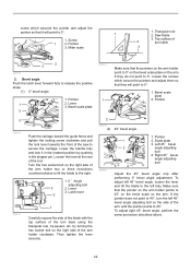
... the pointer on the arm holder points to 45° on the bevel scale on the arm. Loosen the lever at the rear of the saw to 0° on the bevel scale plate on the arm. Lever 3. Right 45 ゚ bevel angle adjusting bolt Adjust the 45° bevel angle ... surface of the arm holder clockwise. Scale plate 3. screw which secure the pointers and adjust them so that they will point to 45°. Pointer 3. Miter scale 1. Top surface of the arm holder two or three revolutions counterclockwise to tilt the blade to release the positive stops. (1) 0° bevel angle 1. Bevel...
... the pointer on the arm holder points to 45° on the bevel scale on the arm. Loosen the lever at the rear of the saw to 0° on the bevel scale plate on the arm. Lever 3. Right 45 ゚ bevel angle adjusting bolt Adjust the 45° bevel angle ... surface of the arm holder clockwise. Scale plate 3. screw which secure the pointers and adjust them so that they will point to 45°. Pointer 3. Miter scale 1. Top surface of the arm holder two or three revolutions counterclockwise to tilt the blade to release the positive stops. (1) 0° bevel angle 1. Bevel...
Owners Manual
Page 25
...; Dust box • Hex wrench (for LS1016L) MAKITA LIMITED ONE YEAR WARRANTY Warranty Policy Every Makita tool is thoroughly inspected and tested before leaving the factory. Non-ferrous metals For miters in aluminum, copper, brass, tubing, miter saw blades For smooth and precise cutting in various materials. ...have been made or attempted by defective workmanship or material, Makita will repair (or at our option, replace) without charge. THIS DISCLAIMER APPLIES BOTH DURING AND AFTER THE TERM OF THIS WARRANTY. Miter saw blades and other rights which vary from state to state....
...; Dust box • Hex wrench (for LS1016L) MAKITA LIMITED ONE YEAR WARRANTY Warranty Policy Every Makita tool is thoroughly inspected and tested before leaving the factory. Non-ferrous metals For miters in aluminum, copper, brass, tubing, miter saw blades For smooth and precise cutting in various materials. ...have been made or attempted by defective workmanship or material, Makita will repair (or at our option, replace) without charge. THIS DISCLAIMER APPLIES BOTH DURING AND AFTER THE TERM OF THIS WARRANTY. Miter saw blades and other rights which vary from state to state....

Parts Breakdown
Page 6
... 1 TAPPING SCREW BIND CT 4X20, 9046 1 SPRING WASHER 6, 5007NB 1 THIN WASHER, 4340FCT 1 DUST BAG ASS'Y, LS1016 1 VISE ASS'Y, LS1016L 1 TRIANGLE RULE, LS1011 1 KNOB M5X16, 2012 2 HOLDER 200, LS1016L/LS1216L 2 BOX WRENCH 13, LS1016 1 10X5/8 60T MITER SAW BLADE, LS1040 1 LS1016 Page 6 of 6 8/18/2010 205 206 207 208 209 210 211 212 213 214 215...
... 1 TAPPING SCREW BIND CT 4X20, 9046 1 SPRING WASHER 6, 5007NB 1 THIN WASHER, 4340FCT 1 DUST BAG ASS'Y, LS1016 1 VISE ASS'Y, LS1016L 1 TRIANGLE RULE, LS1011 1 KNOB M5X16, 2012 2 HOLDER 200, LS1016L/LS1216L 2 BOX WRENCH 13, LS1016 1 10X5/8 60T MITER SAW BLADE, LS1040 1 LS1016 Page 6 of 6 8/18/2010 205 206 207 208 209 210 211 212 213 214 215...

Flyer (English)
Page 1
... CROWN MOLDING CAPACITY IN ITS CLASS 10" Slide Miter Saw with the Crown Molding Cutting Capacity of a 12" Saw Compact Design with a Patented 4-Steel Rail Sliding System Further Increases Rigidity to Produce Superior Cuts Exclusive 6 Linear Ball Bearings Deliver Smooth, Solid, and ... patented 4-steel rail sliding system deliver dead-on cuts PORTABILITY The most compact design in its class for easy jobsite portability VERSATILITY Models LS1016 / LS1016L 4-3/4" tall dual sliding fence system features upper and lower fence adjustments for more precise cuts LARGE CUTTING CAPACITY makitatools.com
... CROWN MOLDING CAPACITY IN ITS CLASS 10" Slide Miter Saw with the Crown Molding Cutting Capacity of a 12" Saw Compact Design with a Patented 4-Steel Rail Sliding System Further Increases Rigidity to Produce Superior Cuts Exclusive 6 Linear Ball Bearings Deliver Smooth, Solid, and ... patented 4-steel rail sliding system deliver dead-on cuts PORTABILITY The most compact design in its class for easy jobsite portability VERSATILITY Models LS1016 / LS1016L 4-3/4" tall dual sliding fence system features upper and lower fence adjustments for more precise cuts LARGE CUTTING CAPACITY makitatools.com
Flyer (English)
Page 2
...94758 A-94764 A-94770 A-93669 A-93675 A-93681 792303-3 Makita offers a wide variety of -blade" cutting (LS1016L only) LS1016/LS1016L LS1016L LS1016/LS1016L LS1016 SPECIFICATIONS OPTIONAL ACCESSORIES Blade diameter 10" Arbor 5/8" Capacities: Bevel range L/R Miter range L/R Cutting capacity at 0º Cutting capacity L/R...independent laser indicates line-of-cut whether blade is engineered for increased vertical cutting capacity I Miters 0º-52º left -of-blade" or "right-of MITER SAW accessories. For a complete listing, please refer to -read markings STANDARD EQUIPMENT I 10"...
...94758 A-94764 A-94770 A-93669 A-93675 A-93681 792303-3 Makita offers a wide variety of -blade" cutting (LS1016L only) LS1016/LS1016L LS1016L LS1016/LS1016L LS1016 SPECIFICATIONS OPTIONAL ACCESSORIES Blade diameter 10" Arbor 5/8" Capacities: Bevel range L/R Miter range L/R Cutting capacity at 0º Cutting capacity L/R...independent laser indicates line-of-cut whether blade is engineered for increased vertical cutting capacity I Miters 0º-52º left -of-blade" or "right-of MITER SAW accessories. For a complete listing, please refer to -read markings STANDARD EQUIPMENT I 10"...

Technical Reference
Page 1
... page for easy cut line alignment. TECHNICAL INFORMATION PRODUCT Models No. LS1016, LS1016L P 1/ 37 Description Slide Compound Miter Saw 255mm (10")*1/ 260mm (10-1/4") [*1 255mm (1") for the tool shown may differ by our consistent pursuit of slide compound miter saws. Optional accessories Horizontal vise TCT saw blades Crown molding stopper set 2 (all countries except North America) Hex...
... page for easy cut line alignment. TECHNICAL INFORMATION PRODUCT Models No. LS1016, LS1016L P 1/ 37 Description Slide Compound Miter Saw 255mm (10")*1/ 260mm (10-1/4") [*1 255mm (1") for the tool shown may differ by our consistent pursuit of slide compound miter saws. Optional accessories Horizontal vise TCT saw blades Crown molding stopper set 2 (all countries except North America) Hex...

Technical Reference
Page 2
Specification (cont.) [Cutting Capacities] North America Cutting capacities [Height x Width in mm (")] with 255mm (10") saw blade Bevel angle Miter angle 45 degrees left 0 degree 47 x 305 (1-7/8 x 12) 61 x 279 (2-3/8 x 11) 45 degrees left & right 47 x 215 (1-7/8 x 8-1/2) 61 x 197 (2-3/8 x... 215 (1-1/8 x 8-1/2) 43 x 197 (1-11/16 x 7-3/4) All countries except North America Cutting capacities [Height x Width in mm] with 260mm (10-1/4") saw blade Bevel angle Miter angle 45 degrees left 0 degree 42 x 310 58 x 279 45 degrees left & right 42 x 218 58 x 197 52 degrees left & right 60 ...
Specification (cont.) [Cutting Capacities] North America Cutting capacities [Height x Width in mm (")] with 255mm (10") saw blade Bevel angle Miter angle 45 degrees left 0 degree 47 x 305 (1-7/8 x 12) 61 x 279 (2-3/8 x 11) 45 degrees left & right 47 x 215 (1-7/8 x 8-1/2) 61 x 197 (2-3/8 x... 215 (1-1/8 x 8-1/2) 43 x 197 (1-11/16 x 7-3/4) All countries except North America Cutting capacities [Height x Width in mm] with 260mm (10-1/4") saw blade Bevel angle Miter angle 45 degrees left 0 degree 42 x 310 58 x 279 45 degrees left & right 42 x 218 58 x 197 52 degrees left & right 60 ...


