Owners Manual
Page 5
... and could burn your skin. 13. Don't use guards and eye shields. 5. Store wheels in cold weather. Watch for speed of the wheel only. Use the upper surface of grinder. 3. Use grinding wheel suitable for flutter that might break. 5. Be careful not t o damage the spindle or...Keep a space of 5 m m (3/16") between the sharpening platform guide (rail) and the grinding wheel. 6. If the wheel stops during operation, makes an odd noise or begins t o vibrate, switch off and wait for the wheel t o come t o a complete stop be caused by idling the tool after operation, it run...
... and could burn your skin. 13. Don't use guards and eye shields. 5. Store wheels in cold weather. Watch for speed of the wheel only. Use the upper surface of grinder. 3. Use grinding wheel suitable for flutter that might break. 5. Be careful not t o damage the spindle or...Keep a space of 5 m m (3/16") between the sharpening platform guide (rail) and the grinding wheel. 6. If the wheel stops during operation, makes an odd noise or begins t o vibrate, switch off and wait for the wheel t o come t o a complete stop be caused by idling the tool after operation, it run...
Owners Manual
Page 6
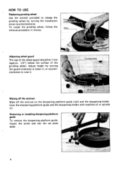
To install the grinding wheel, follow the removal procedure in reverse. Coat the sharpening platform guide and the sharpening holder with machine oil or spindle oil. Wiping off the antirust ... platform guide, loosen the screw and slip the set plate aside. 6 Adjusting wheel guard The top of the wheel guard should be 1 mm (approx. 1/3") below the surface of the grinding wheel. HOW TO USE Replacing grinding wheel Use the wrench provided to release the grinding wheel by turning the guard clockwiseto lower it, or counterclockwise to raise it.
To install the grinding wheel, follow the removal procedure in reverse. Coat the sharpening platform guide and the sharpening holder with machine oil or spindle oil. Wiping off the antirust ... platform guide, loosen the screw and slip the set plate aside. 6 Adjusting wheel guard The top of the wheel guard should be 1 mm (approx. 1/3") below the surface of the grinding wheel. HOW TO USE Replacing grinding wheel Use the wrench provided to release the grinding wheel by turning the guard clockwiseto lower it, or counterclockwise to raise it.
Owners Manual
Page 8
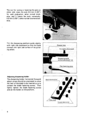
Blade I \ Forward adiurt screw I I I The sharpening holder horizontal (forward) adjust screws should be unscrewedto allow the heel of the grinding wheel. Tilt the sharpening platform guide slightly with right side downward so that the blade contacts the right side surface of the blade to be inserted ...
Blade I \ Forward adiurt screw I I I The sharpening holder horizontal (forward) adjust screws should be unscrewedto allow the heel of the grinding wheel. Tilt the sharpening platform guide slightly with right side downward so that the blade contacts the right side surface of the blade to be inserted ...
Owners Manual
Page 9
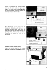
Screw in the left upper edge of the blade comes into the grooves provided for them on the horizontal. Slide the holder to secure the blade on the sharpener frame. 9 Screw in clockwise the forward adjust screw on the right until the left -hand forward adjust screw until the right upper edge of the blade contacts the grinding wheel. Now use all four fastening screws to the right across the sharpening platform guide. Installingcoolant reservoir (Tank) Insert the reservoir legs into contact with the grinding wheel. Then fully tighten the fastening screw on the far right.
Screw in the left upper edge of the blade comes into the grooves provided for them on the horizontal. Slide the holder to secure the blade on the sharpener frame. 9 Screw in clockwise the forward adjust screw on the right until the left -hand forward adjust screw until the right upper edge of the blade contacts the grinding wheel. Now use all four fastening screws to the right across the sharpening platform guide. Installingcoolant reservoir (Tank) Insert the reservoir legs into contact with the grinding wheel. Then fully tighten the fastening screw on the far right.
Owners Manual
Page 10
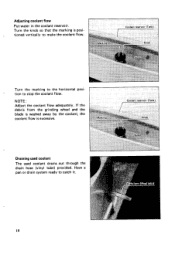
tion to catch it. 10 Have a pan or drain system ready to stop the coolant flow. r Turn the marking to make the coolant flow. NOTE : Adjust the coolant flow adequately. Adjusting coolant flow Put water in the coolant reservoir. If the debris from the grinding wheel and the blade is washed away by the coolant, the coolant flow is excessive. Draining used coolant The used coolant drains out through the drain hose (vinyl tube) provided. Turn the knob so that the marking i s positioned vertically to the horizontal posi-
tion to catch it. 10 Have a pan or drain system ready to stop the coolant flow. r Turn the marking to make the coolant flow. NOTE : Adjust the coolant flow adequately. Adjusting coolant flow Put water in the coolant reservoir. If the debris from the grinding wheel and the blade is washed away by the coolant, the coolant flow is excessive. Draining used coolant The used coolant drains out through the drain hose (vinyl tube) provided. Turn the knob so that the marking i s positioned vertically to the horizontal posi-
Owners Manual
Page 13
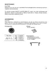
... inspection and maintenance. Part No. 132386-5 13 The accessories or attachments should be performed by Makita Authorized or Factory Service Centers, always using makita replacement parts. MAINTENANCE CAUTION : Always be used only in the proper and intended manner. 0 Grinding wheels Wrench Part No. 341 391 - 3 Size (mm) I Grit I Part No. 200x25~75 (7-7/8" x 1" x 3") 741074-9 Guide...
... inspection and maintenance. Part No. 132386-5 13 The accessories or attachments should be performed by Makita Authorized or Factory Service Centers, always using makita replacement parts. MAINTENANCE CAUTION : Always be used only in the proper and intended manner. 0 Grinding wheels Wrench Part No. 341 391 - 3 Size (mm) I Grit I Part No. 200x25~75 (7-7/8" x 1" x 3") 741074-9 Guide...
Parts Breakdown
Page 2
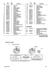
...TYPE 1 PART# 155220-2 (Discontinued) TYPE 2 PART# 151274-7 PART# 267040-3 (2 ea.) (See Service Change 2) 2 MODEL 9820-2 01-96 No. No. Used Description 1 271235-2 1 LOCK NUT 2 412033-7 1 TUBE 3 411429-9 1 WHEEL COVER 4 911231-5 2 SCREW M5X20 5 341392-1 2 SET PLATE 6 251847-7 2 KNOB M6X31 8 912002-3 2 C.H.SCREW M3X6...401 123061-4A 1 404 341391-3 1 405 741070-7 1 410 122209-5 1 BLADEHOLDER ASSEMBLY (Assembled with Fig.60-62) WRENCH GRINDING WHEEL #IO00 (Medium) RAIL ASSEMBLY (Assembled with Fig.37-47) *SEE SERVICE CHANGE 1 *"SEE SERVICE CHANGE 2 SERVICE CHANGE 1) Change on ...
...TYPE 1 PART# 155220-2 (Discontinued) TYPE 2 PART# 151274-7 PART# 267040-3 (2 ea.) (See Service Change 2) 2 MODEL 9820-2 01-96 No. No. Used Description 1 271235-2 1 LOCK NUT 2 412033-7 1 TUBE 3 411429-9 1 WHEEL COVER 4 911231-5 2 SCREW M5X20 5 341392-1 2 SET PLATE 6 251847-7 2 KNOB M6X31 8 912002-3 2 C.H.SCREW M3X6...401 123061-4A 1 404 341391-3 1 405 741070-7 1 410 122209-5 1 BLADEHOLDER ASSEMBLY (Assembled with Fig.60-62) WRENCH GRINDING WHEEL #IO00 (Medium) RAIL ASSEMBLY (Assembled with Fig.37-47) *SEE SERVICE CHANGE 1 *"SEE SERVICE CHANGE 2 SERVICE CHANGE 1) Change on ...

