
Owners Manual
Page 1
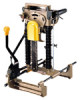
MODEL 7104L INSTRUCTION MANUAL S P E C IF I CATIONS 7 7 1 Capacities Width of applicable workpiece iLonglludlndll hole depth 130 r n n 1 1518 I 155 m m 16 1 8 I 80 m m 308 mni 13 1/8 12 1 8 i Chain speed 300 m min !l 000 FPMi Dimensions !LxWxHI 512 m m x 2 9 8 m m x 513 m m 120 3 16 x 1 1 314 x 20 3/16 I Net weight 17 kg 137 4 lhsi
MODEL 7104L INSTRUCTION MANUAL S P E C IF I CATIONS 7 7 1 Capacities Width of applicable workpiece iLonglludlndll hole depth 130 r n n 1 1518 I 155 m m 16 1 8 I 80 m m 308 mni 13 1/8 12 1 8 i Chain speed 300 m min !l 000 FPMi Dimensions !LxWxHI 512 m m x 2 9 8 m m x 513 m m 120 3 16 x 1 1 314 x 20 3/16 I Net weight 17 kg 137 4 lhsi

Owners Manual
Page 2
... keys. 8. Use clamps or a vise t o hold work area well lighted. 6 . REDUCE THE RISK OF UNINTENTIONAL STARTING. Read the owner's manual carefully. Form habit of injury t o persons. All visitors should be kept safe distance from tool before servicing; U S E RIGHT TOOL. IO. Consult the... owner's manual for best and safest performance. BEFORE CONNECTING YOUR TOOL TO A POWER SOURCE Be sure you have impact resistant lenses, they are removed from work...
... keys. 8. Use clamps or a vise t o hold work area well lighted. 6 . REDUCE THE RISK OF UNINTENTIONAL STARTING. Read the owner's manual carefully. Form habit of injury t o persons. All visitors should be kept safe distance from tool before servicing; U S E RIGHT TOOL. IO. Consult the... owner's manual for best and safest performance. BEFORE CONNECTING YOUR TOOL TO A POWER SOURCE Be sure you have impact resistant lenses, they are removed from work...

Owners Manual
Page 13
...mm (1-3/16") Part No. 221502-5 I To remove the standard-equipped sprocket, in- The accessories or attachments should be used only in this manual. To install the chain bar for use of any other accessories or attachments might present a risk of injury t o persons. ACCESSORIES CAUTION ... for 30 m m (1-3/16"). 0 Chain bar for 30 mm (1-3/16"). To install the sprocket for 30" (1-3/16"), mount the sprocket onto the spindle with your Makita tool specified in the proper and intended manner. 0 Cutter chain 0 Sharpening holder assembly Part No. 123028-2 I 7 9 1 084-6 791088-8 *791174-5 Width 1 ...
...mm (1-3/16") Part No. 221502-5 I To remove the standard-equipped sprocket, in- The accessories or attachments should be used only in this manual. To install the chain bar for use of any other accessories or attachments might present a risk of injury t o persons. ACCESSORIES CAUTION ... for 30 m m (1-3/16"). 0 Chain bar for 30 mm (1-3/16"). To install the sprocket for 30" (1-3/16"), mount the sprocket onto the spindle with your Makita tool specified in the proper and intended manner. 0 Cutter chain 0 Sharpening holder assembly Part No. 123028-2 I 7 9 1 084-6 791088-8 *791174-5 Width 1 ...


