
Owners Manual
Page 4
...cut holes in wood. 2. Place the workpiece on wood blocks or short beams t o prevent the cutter chain from moving parts. 12. Replace cracked or damaged cutter chain immediately. 7 . Check the cutter chain carefully for and remove nails or foreign matter from falling off and possibly causing injury. 13. Keep ...hands away from hitting the ground, floor, etc., causing damage t o the cutter chain at the time of hole breakthrough. 6. it from the workpiece before operation. Inspect for cracks or damage before operation. 9. Wear ear ...
...cut holes in wood. 2. Place the workpiece on wood blocks or short beams t o prevent the cutter chain from moving parts. 12. Replace cracked or damaged cutter chain immediately. 7 . Check the cutter chain carefully for and remove nails or foreign matter from falling off and possibly causing injury. 13. Keep ...hands away from hitting the ground, floor, etc., causing damage t o the cutter chain at the time of hole breakthrough. 6. it from the workpiece before operation. Inspect for cracks or damage before operation. 9. Wear ear ...

Owners Manual
Page 5
... adjusting the tension, tighten the hex bolt firmly to increase the tension o n the cutter chain. Close the chain cover. To remove the cutter chain, follow the installation procedures in the direction of the arrow on the cutter chain is adequate. Orient the cutters in reverse. 5 Installing o r removing cutter chain WARNING: .Always be sure that the tool is a clearance of the...
... adjusting the tension, tighten the hex bolt firmly to increase the tension o n the cutter chain. Close the chain cover. To remove the cutter chain, follow the installation procedures in the direction of the arrow on the cutter chain is adequate. Orient the cutters in reverse. 5 Installing o r removing cutter chain WARNING: .Always be sure that the tool is a clearance of the...

Owners Manual
Page 7
... actuates properly and returns to the tool. Switch on either side. After cutting, gently raise the tool head until the cutter chain attains full speed. Adjusting indicator plate and indication plate The yellow indicator plate and indication plate are factory adjusted for some reason..., or when using another size cutter chain, loosen the screws and adjust the yellow indicator plate and indication plate. the time of a cutting operation, a t - If the...
... actuates properly and returns to the tool. Switch on either side. After cutting, gently raise the tool head until the cutter chain attains full speed. Adjusting indicator plate and indication plate The yellow indicator plate and indication plate are factory adjusted for some reason..., or when using another size cutter chain, loosen the screws and adjust the yellow indicator plate and indication plate. the time of a cutting operation, a t - If the...

Owners Manual
Page 8
...predetermined may be c u t 52.5 mm (2-1/16") 52.5 mm (2-1/16")- 105 mm (4-1/8") 77.5 mm (3-1/16") - 130 mm (5-1/8") NOTE : . Cutter chain position Original position No. 1 set position No. 2 set position. 8 Loosen the hex bolts securing the gauge plate. Longitudinal (length) enlargement Hole length can ...away from you . Then pull the lever (B) toward you and cut depending upon the cutter chain tension. .The adjusting hex bolts are factory adjusted for cutting a hole 30 mm (1-3/16") wide using a cutter chain 18mm (23/32"), proceed as follows: Push the lever (B) away from you ....
...predetermined may be c u t 52.5 mm (2-1/16") 52.5 mm (2-1/16")- 105 mm (4-1/8") 77.5 mm (3-1/16") - 130 mm (5-1/8") NOTE : . Cutter chain position Original position No. 1 set position No. 2 set position. 8 Loosen the hex bolts securing the gauge plate. Longitudinal (length) enlargement Hole length can ...away from you . Then pull the lever (B) toward you and cut depending upon the cutter chain tension. .The adjusting hex bolts are factory adjusted for cutting a hole 30 mm (1-3/16") wide using a cutter chain 18mm (23/32"), proceed as follows: Push the lever (B) away from you ....

Owners Manual
Page 9
... you while pressing down the right-hand grip while raising the left -hand grip and move the cutter chain back to slip off the set position. Turn the adjusting hex bolt until the cutter chain reaches the desired position, then tighten the hex nut. When cutting a hole, first use the ...dicular position, then No. 1 set position and finally No. 2 set position. Always safely hook the tool head back onto the hook when changing the cutter chain position. 9 Push down on the right-hand grip and slightly raising the left -hand grip. I Adjusting hex bolt -for No. 1 set Dosition WARNING...
... you while pressing down the right-hand grip while raising the left -hand grip and move the cutter chain back to slip off the set position. Turn the adjusting hex bolt until the cutter chain reaches the desired position, then tighten the hex nut. When cutting a hole, first use the ...dicular position, then No. 1 set position and finally No. 2 set position. Always safely hook the tool head back onto the hook when changing the cutter chain position. 9 Push down on the right-hand grip and slightly raising the left -hand grip. I Adjusting hex bolt -for No. 1 set Dosition WARNING...

Owners Manual
Page 10
... to 130 mm (5-1/8") can be c u t with the cutter chain still within the hole. This makes for more easy and efficient hole enlargement. NOTE : Lap joints can be cut only on the front (side away ... transversely I and longitudinally, c u t the holes in the order indicated from you) of the workpiece. 10 This will cause unstable and dangerous operation. 0 Never angle the cutter chain when cutting the first hole, or a dangerous kickback may result. Front base 4 WARNING: 0Never attempt to (6) as shown. Lap joints u p to the perpendicular position when...
... to 130 mm (5-1/8") can be c u t with the cutter chain still within the hole. This makes for more easy and efficient hole enlargement. NOTE : Lap joints can be cut only on the front (side away ... transversely I and longitudinally, c u t the holes in the order indicated from you) of the workpiece. 10 This will cause unstable and dangerous operation. 0 Never angle the cutter chain when cutting the first hole, or a dangerous kickback may result. Front base 4 WARNING: 0Never attempt to (6) as shown. Lap joints u p to the perpendicular position when...

Owners Manual
Page 11
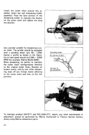
... remove dirt, chips and foreign matter adhering to the limit mark. Then oil the moving parts (especially cutter chain) and the contact portions. Sharpening cutter chain Remove the chain bar and cutter chain from the sharpening holder assembly. Keep the carbon brushes clean and free to perform inspection or maintenance. Take...washer and hex bolt from the tool. MAINTENANCE CAUTION : Always be replaced at the same time. Use only Makita carbon brushes. Insert the hex bolt through t h e hole in the chain bar so that the tool is switched off and unplugged before attempting to slip in the...
... remove dirt, chips and foreign matter adhering to the limit mark. Then oil the moving parts (especially cutter chain) and the contact portions. Sharpening cutter chain Remove the chain bar and cutter chain from the sharpening holder assembly. Keep the carbon brushes clean and free to perform inspection or maintenance. Take...washer and hex bolt from the tool. MAINTENANCE CAUTION : Always be replaced at the same time. Use only Makita carbon brushes. Insert the hex bolt through t h e hole in the chain bar so that the tool is switched off and unplugged before attempting to slip in the...
Owners Manual
Page 12
... and sharpening holder assembly). Install the cutter chain around this as shown in the figure. Use a grinder suitable for example, Makita Model 9300). Sharpen all cutters evenly, one by Makita Authorized or Factory Service Centers, always using Makita replacement parts. 12 The grinder should be equipped with a grinding wheel (grit 60 - 1.000) having a profile as - After...
... and sharpening holder assembly). Install the cutter chain around this as shown in the figure. Use a grinder suitable for example, Makita Model 9300). Sharpen all cutters evenly, one by Makita Authorized or Factory Service Centers, always using Makita replacement parts. 12 The grinder should be equipped with a grinding wheel (grit 60 - 1.000) having a profile as - After...

Owners Manual
Page 13
...use with the round hole side facing in. Then secure using a cutter chain 30 m m (1-3/16"), remove the standard-equipped chain bar and sprocket, and install the chain bar for 30 mm (1-3/16") and sprocket for 30 m m (1-3/16"). 0 Chain bar for 30 m m (1-3/16"), first install the adjust- ing .... 0 Sprocket 4 for 30" (1-3/16"), mount the sprocket onto the spindle with your Makita tool specified in - I 791085-4 I 7 9 1 0 8 6 - 2 I 79- 108-7-0 I Part NO. Remove the adjusting screw from the chain bar. The accessories or attachments should be used only in the figure to lock the sprocket...
...use with the round hole side facing in. Then secure using a cutter chain 30 m m (1-3/16"), remove the standard-equipped chain bar and sprocket, and install the chain bar for 30 mm (1-3/16") and sprocket for 30 m m (1-3/16"). 0 Chain bar for 30 m m (1-3/16"), first install the adjust- ing .... 0 Sprocket 4 for 30" (1-3/16"), mount the sprocket onto the spindle with your Makita tool specified in - I 791085-4 I 7 9 1 0 8 6 - 2 I 79- 108-7-0 I Part NO. Remove the adjusting screw from the chain bar. The accessories or attachments should be used only in the figure to lock the sprocket...

Owners Manual
Page 16
MODEL 7104L ,& DESCRIPTION & DESCRIPTION F s b - 0 1 - 0 9 EN MACHINE ~ 1 1 2 1 3 2 4 1 5 1 6 1 7 2 8 1 9 3 10 2 11...) Indicalor Plate Pan Head Screw M 4 x 8 (With Washer) Bare FIm Washer 24 aeiiow. MA1 ut 73 1 cutter Chal" 14 1 " O K Shs'l 75 I Cham Bar 76 1 B ~ IaIearsng ioo8tt 77 1 Toothed Lock Washer...1 0 lWiih Washer1 Tsn3lon sprmng 2 0 Hex 8011 M 0 x 4 4 Hex Nul M 0 Lever c Tension Spring 1 2 Pl" 10 s p m g P," 4 20 Chain Cove! Anjo, Aichi, Japan 883685 - 5 P R I 0 Spring Washer 10 Flat Washer 10 Screw M 0 i 2 8 s w n g Pm 4 2 0 Her Boll...
MODEL 7104L ,& DESCRIPTION & DESCRIPTION F s b - 0 1 - 0 9 EN MACHINE ~ 1 1 2 1 3 2 4 1 5 1 6 1 7 2 8 1 9 3 10 2 11...) Indicalor Plate Pan Head Screw M 4 x 8 (With Washer) Bare FIm Washer 24 aeiiow. MA1 ut 73 1 cutter Chal" 14 1 " O K Shs'l 75 I Cham Bar 76 1 B ~ IaIearsng ioo8tt 77 1 Toothed Lock Washer...1 0 lWiih Washer1 Tsn3lon sprmng 2 0 Hex 8011 M 0 x 4 4 Hex Nul M 0 Lever c Tension Spring 1 2 Pl" 10 s p m g P," 4 20 Chain Cove! Anjo, Aichi, Japan 883685 - 5 P R I 0 Spring Washer 10 Flat Washer 10 Screw M 0 i 2 8 s w n g Pm 4 2 0 Her Boll...

Parts Breakdown
Page 4
... 1 COMP. WASHER 9, 7104L 1 SLEEVE 9, 7104L 1 TENSION SPRING 9, 7104L 1 SPRING PIN 4-16, 2030S 1 SLIDE BAR, 7104L 1 SPRING PIN 5-20, 2414B 1 P.H. SPRING 48, 7104L 1 VISE SHOE, 7104L 1 Page 4 of 5 7104L 8/18/2010 SPRING 25, 7104L 2 DISC, 7104L 1 SPRING PIN 6-24, 5600B 2 CHAIN BAR HOLDER, 7104L 1 SPRING PIN 5-40, 7104L 1 CUTTER CHAIN BLADE 18, 7104L 1 HEAD SHAFT, 7104L 1 CHAIN BAR ASSEMBLY 15-24MM, 7104L 1 BALL BEARING 1008LL, 7104L 1 TOOTHED WASHER 6, 7104L 1 COUNTERSUNK HEAD...
... 1 COMP. WASHER 9, 7104L 1 SLEEVE 9, 7104L 1 TENSION SPRING 9, 7104L 1 SPRING PIN 4-16, 2030S 1 SLIDE BAR, 7104L 1 SPRING PIN 5-20, 2414B 1 P.H. SPRING 48, 7104L 1 VISE SHOE, 7104L 1 Page 4 of 5 7104L 8/18/2010 SPRING 25, 7104L 2 DISC, 7104L 1 SPRING PIN 6-24, 5600B 2 CHAIN BAR HOLDER, 7104L 1 SPRING PIN 5-40, 7104L 1 CUTTER CHAIN BLADE 18, 7104L 1 HEAD SHAFT, 7104L 1 CHAIN BAR ASSEMBLY 15-24MM, 7104L 1 BALL BEARING 1008LL, 7104L 1 TOOTHED WASHER 6, 7104L 1 COUNTERSUNK HEAD...

Flyer (English)
Page 1
... SLIDING REAR CLAMP adjust to make product specification changes without notice. Makita reserves the right to make any obligation and without being required to desired width (quick adjust tension knob) Model 7104L Specifications Capacities: Max. Cut 2-1/16" TO Max. Cut 5-1/8" ...; 100cc Oil Supply (182229-1) Accessories • Cutter Chain Width Part Number 5/8" (15 mm) (791085-4) 21/32" (16.5 mm) 11/16" (18 mm) (791086-2) (791087-0) $ 13/16" (21 mm) (791084-6) 15/16" (24 mm) (791088-8) Makita U.S.A., Inc. CHAIN TENSION adjustment cover (snap action cover) CLAMP TENSION...
... SLIDING REAR CLAMP adjust to make product specification changes without notice. Makita reserves the right to make any obligation and without being required to desired width (quick adjust tension knob) Model 7104L Specifications Capacities: Max. Cut 2-1/16" TO Max. Cut 5-1/8" ...; 100cc Oil Supply (182229-1) Accessories • Cutter Chain Width Part Number 5/8" (15 mm) (791085-4) 21/32" (16.5 mm) 11/16" (18 mm) (791086-2) (791087-0) $ 13/16" (21 mm) (791084-6) 15/16" (24 mm) (791088-8) Makita U.S.A., Inc. CHAIN TENSION adjustment cover (snap action cover) CLAMP TENSION...


