
Owners Manual
Page 1
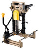
MODEL 7104L INSTRUCTION MANUAL S P E C IF I CATIONS 7 7 1 Capacities Width of applicable workpiece iLonglludlndll hole depth 130 r n n 1 1518 I 155 m m 16 1 8 I 80 m m 308 mni 13 1/8 12 1 8 i Chain speed 300 m min !l 000 FPMi Dimensions !LxWxHI 512 m m x 2 9 8 m m x 513 m m 120 3 16 x 1 1 314 x 20 3/16 I Net weight 17 kg 137 4 lhsi
MODEL 7104L INSTRUCTION MANUAL S P E C IF I CATIONS 7 7 1 Capacities Width of applicable workpiece iLonglludlndll hole depth 130 r n n 1 1518 I 155 m m 16 1 8 I 80 m m 308 mni 13 1/8 12 1 8 i Chain speed 300 m min !l 000 FPMi Dimensions !LxWxHI 512 m m x 2 9 8 m m x 513 m m 120 3 16 x 1 1 314 x 20 3/16 I Net weight 17 kg 137 4 lhsi

Owners Manual
Page 4
...the workpiece after operation to the workpiece firmly. 8. Keep cord away from hitting the ground, floor, etc., causing damage t o the cutter chain at the time of hole breakthrough. 6. Secure the tool to keep it from falling off and possibly causing injury. 13. it for cutting ... open. Do not wear gloves during operation. 1 1 . Never u s e it is for cutting holes in a log. 3. Replace cracked or damaged cutter chain immediately. 7 . Use this tool only t o cut holes in flat-surfaced wood. Keep hands away from the workpiece before operation. SAVE THESE INSTRUCTIONS. 4 Inspect...
...the workpiece after operation to the workpiece firmly. 8. Keep cord away from hitting the ground, floor, etc., causing damage t o the cutter chain at the time of hole breakthrough. 6. Secure the tool to keep it from falling off and possibly causing injury. 13. it for cutting ... open. Do not wear gloves during operation. 1 1 . Never u s e it is for cutting holes in a log. 3. Replace cracked or damaged cutter chain immediately. 7 . Use this tool only t o cut holes in flat-surfaced wood. Keep hands away from the workpiece before operation. SAVE THESE INSTRUCTIONS. 4 Inspect...

Owners Manual
Page 5
... adjusting screw. When there is a clearance of the arrow on the cutter chain is switched off and unplugged before installing or removing the cutter chain. .Always close the chain cover after installing, removing or adjusting the cutter chain. To remove the cutter chain, follow the installation procedures in the direction of approx. 5 -- 6 mm W16" - 1/4") between...
... adjusting screw. When there is a clearance of the arrow on the cutter chain is switched off and unplugged before installing or removing the cutter chain. .Always close the chain cover after installing, removing or adjusting the cutter chain. To remove the cutter chain, follow the installation procedures in the direction of approx. 5 -- 6 mm W16" - 1/4") between...

Owners Manual
Page 7
Release the trigger to the tool. the time of a cutting operation, a t - After cutting, gently raise the tool head until the cutter chain attains full speed. Operation Grasp firmly the grips on the tool and wait until you can hook the tool head back onto the hook. Then ...switch off , for the standardequipped cutter chain 18 mm (23/32"). Raise the lever (A) and remove the tool from the workpiece. Switch on either side. Feed slowly a t the beginning of hole breakthrough...
Release the trigger to the tool. the time of a cutting operation, a t - After cutting, gently raise the tool head until the cutter chain attains full speed. Operation Grasp firmly the grips on the tool and wait until you can hook the tool head back onto the hook. Then ...switch off , for the standardequipped cutter chain 18 mm (23/32"). Raise the lever (A) and remove the tool from the workpiece. Switch on either side. Feed slowly a t the beginning of hole breakthrough...

Owners Manual
Page 8
...proceed as follows: Push the lever (B) away from you and cut depending upon the cutter chain tension. .The adjusting hex bolts are factory adjusted for cutting a hole 30 mm (1-3/16") wide using a cutter chain 18 mm (23/32"). 2. Loosen the hex bolts securing the gauge plate. Longitudinal (length...) enlargement Hole length can be c u t 52.5 mm (2-1/16") 52.5 mm (2-1/16")- 105 mm (4-1/8") 77.5 mm (3-1/16") - 130 mm (5-1/8") NOTE : . Cutter chain position Original position No. 1 set position No. 2 set position and 120 mm (4-3/4")long in the table below. Enlarging hole 1. ILlaR.
...proceed as follows: Push the lever (B) away from you and cut depending upon the cutter chain tension. .The adjusting hex bolts are factory adjusted for cutting a hole 30 mm (1-3/16") wide using a cutter chain 18 mm (23/32"). 2. Loosen the hex bolts securing the gauge plate. Longitudinal (length...) enlargement Hole length can be c u t 52.5 mm (2-1/16") 52.5 mm (2-1/16")- 105 mm (4-1/8") 77.5 mm (3-1/16") - 130 mm (5-1/8") NOTE : . Cutter chain position Original position No. 1 set position No. 2 set position and 120 mm (4-3/4")long in the table below. Enlarging hole 1. ILlaR.

Owners Manual
Page 9
...No. 2 set position. When cutting a hole, first use the perpen- Loosen the hex n u t securing the adjusting hex bolt. To bring the cutter chain back t o the perpendicular (original) position, pull the lever (C) toward you while pressing down the right-hand grip while raising the left -hand grip and move... the cutter chain back to slip off the set Dosition WARNING: When using pressure to t u r n the adjusting hex bolt or hex n u t , be careful not...
...No. 2 set position. When cutting a hole, first use the perpen- Loosen the hex n u t securing the adjusting hex bolt. To bring the cutter chain back t o the perpendicular (original) position, pull the lever (C) toward you while pressing down the right-hand grip while raising the left -hand grip and move... the cutter chain back to slip off the set Dosition WARNING: When using pressure to t u r n the adjusting hex bolt or hex n u t , be careful not...

Owners Manual
Page 10
... for more easy and efficient hole enlargement. This will cause unstable and dangerous operation. 0 Never angle the cutter chain when cutting the first hole, or a dangerous kickback may result. Always have the cutter chain set to enlarge a hole with this tool. Front base 4 WARNING: 0Never attempt to the perpendicular position when cutting...
... for more easy and efficient hole enlargement. This will cause unstable and dangerous operation. 0 Never angle the cutter chain when cutting the first hole, or a dangerous kickback may result. Always have the cutter chain set to enlarge a hole with this tool. Front base 4 WARNING: 0Never attempt to the perpendicular position when cutting...

Owners Manual
Page 11
...that the tool is switched off and unplugged before attempting to slip in the chain bar. I \ Cutter chain 11 Keep the carbon brushes clean and free to perform inspection or maintenance. Use only Makita carbon brushes. Replacing carbon brushes Remove and check the carbon brushes regularly. Remove ...the wing nut, flat washer and hex bolt from the chain bar. Take out the worn carbon brushes, insert the new...
...that the tool is switched off and unplugged before attempting to slip in the chain bar. I \ Cutter chain 11 Keep the carbon brushes clean and free to perform inspection or maintenance. Use only Makita carbon brushes. Replacing carbon brushes Remove and check the carbon brushes regularly. Remove ...the wing nut, flat washer and hex bolt from the chain bar. Take out the worn carbon brushes, insert the new...
Owners Manual
Page 12
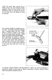
...holder assembly). Grinding wheel R 1.5mm (1/16") Portion to the cutter chain and then oil the link portions. Sharpen all cutters evenly, one by Makita Authorized or Factory Service Centers, always using Makita replacement parts. 12 After sharpening, wipe off any foreign matter adhering ... adjustment should be careful to maintain the cutter chain configurations identical to maintain the tension on the cutter chain and tighten the wing nut securely. When sharpening, be performed by one. Use a grinder suitable for example, Makita Model 9300). Its no load speed should be...
...holder assembly). Grinding wheel R 1.5mm (1/16") Portion to the cutter chain and then oil the link portions. Sharpen all cutters evenly, one by Makita Authorized or Factory Service Centers, always using Makita replacement parts. 12 After sharpening, wipe off any foreign matter adhering ... adjustment should be careful to maintain the cutter chain configurations identical to maintain the tension on the cutter chain and tighten the wing nut securely. When sharpening, be performed by one. Use a grinder suitable for example, Makita Model 9300). Its no load speed should be...

Owners Manual
Page 13
... mm (1-3/16"). To install the sprocket for 30 m m (1-3/16"), first install the adjust- To install the chain bar for 30" (1-3/16"), mount the sprocket onto the spindle with your Makita tool specified in . Hex nut 13 The use with the round hole side facing in this manual. sert a ...slotted screwdriver as shown in - The accessories or attachments should be used only in the proper and intended manner. 0 Cutter chain 0 Sharpening holder assembly Part...
... mm (1-3/16"). To install the sprocket for 30 m m (1-3/16"), first install the adjust- To install the chain bar for 30" (1-3/16"), mount the sprocket onto the spindle with your Makita tool specified in . Hex nut 13 The use with the round hole side facing in this manual. sert a ...slotted screwdriver as shown in - The accessories or attachments should be used only in the proper and intended manner. 0 Cutter chain 0 Sharpening holder assembly Part...

Owners Manual
Page 16
... ComDrer.,on s p m g 7 Hex Nut M 8 lndicslion Plate Pan Head Screw M4x8 lWilh Washer) Indicalor Plate Pan Head Screw M 4 x 8 (With Washer) Bare FIm Washer 24 aeiiow. MODEL 7104L ,& DESCRIPTION & DESCRIPTION F s b - 0 1 - 0 9 EN MACHINE ~ 1 1 2 1 3 2 4 1 5 1 6 1 7 2 8 1 9 3 10 2 11 1 12 1 13 1 14 1 15 1 16 2 I7 2 18 2 19 3 20 1 21 1 22 2 23 1 24 1 25 1 ...0 IWilh Warherl Grio 25 G W Holdsr L Pan Head Screw M 5 x 1 0 lWiih Washer1 Tsn3lon sprmng 2 0 Hex 8011 M 0 x 4 4 Hex Nul M 0 Lever c Tension Spring 1 2 Pl" 10 s p m g P," 4 20 Chain Cove!
... ComDrer.,on s p m g 7 Hex Nut M 8 lndicslion Plate Pan Head Screw M4x8 lWilh Washer) Indicalor Plate Pan Head Screw M 4 x 8 (With Washer) Bare FIm Washer 24 aeiiow. MODEL 7104L ,& DESCRIPTION & DESCRIPTION F s b - 0 1 - 0 9 EN MACHINE ~ 1 1 2 1 3 2 4 1 5 1 6 1 7 2 8 1 9 3 10 2 11 1 12 1 13 1 14 1 15 1 16 2 I7 2 18 2 19 3 20 1 21 1 22 2 23 1 24 1 25 1 ...0 IWilh Warherl Grio 25 G W Holdsr L Pan Head Screw M 5 x 1 0 lWiih Washer1 Tsn3lon sprmng 2 0 Hex 8011 M 0 x 4 4 Hex Nul M 0 Lever c Tension Spring 1 2 Pl" 10 s p m g P," 4 20 Chain Cove!

Parts Breakdown
Page 3
... CARBON BRUSH SET 154,5402A CARBON BRUSH SET CB-154, UC3530A BRUSH HOLDER CAP, 5007MG P.H. BOLT M8X44, 7104L HEX NUT M8, 5037NB LEVER C, 7104L TOR. SPRING 12, 7104 PIN 10, 7104L SPRING PIN 4-20, 9031 CHAIN COVER, 7104L HEX. SCREW M4X8, HR2210 Page 3 of 5 Quantity 1 1 2 1 1 1 2 1 3 2 1 1 1 1 1 1 2 1 1 2 3 1 1 2 1 1 1 1 1 1 1 1 1 1 1 1 1 1 1 1 2 4 3 3 1 1 2 1 1 2 1 1 1 1 1 1 1 1 1 1 1 1 1 2 8/18/2010 SCREW M4X8, 2708 P.H. SCREW M5X10, 1806B TENSION SPRING...
... CARBON BRUSH SET 154,5402A CARBON BRUSH SET CB-154, UC3530A BRUSH HOLDER CAP, 5007MG P.H. BOLT M8X44, 7104L HEX NUT M8, 5037NB LEVER C, 7104L TOR. SPRING 12, 7104 PIN 10, 7104L SPRING PIN 4-20, 9031 CHAIN COVER, 7104L HEX. SCREW M4X8, HR2210 Page 3 of 5 Quantity 1 1 2 1 1 1 2 1 3 2 1 1 1 1 1 1 2 1 1 2 3 1 1 2 1 1 1 1 1 1 1 1 1 1 1 1 1 1 1 1 2 4 3 3 1 1 2 1 1 2 1 1 1 1 1 1 1 1 1 1 1 1 1 2 8/18/2010 SCREW M4X8, 2708 P.H. SCREW M5X10, 1806B TENSION SPRING...

Parts Breakdown
Page 4
.... WASHER 9, 7104L 1 PIN 9, 7104L 1 F. WASHER 9, 7104L 1 SLEEVE 9, 7104L 1 TENSION SPRING 9, 7104L 1 SPRING PIN 4-16, 2030S 1 SLIDE BAR, 7104L 1 SPRING PIN 5-20, 2414B 1 P.H. BOLT M12X34, 7104L 1 VICE ELEMENT, 7104L 1 SCREW M14, 7104L 1 SPRING PIN 4-20, 9031 1 F. SCREW M5X10, 5402A 1 GUIDE POLE, 7104L 1 COMP. SPRING 25, 7104L 2 DISC, 7104L 1 SPRING PIN 6-24, 5600B 2 CHAIN BAR HOLDER, 7104L 1 SPRING PIN 5-40, 7104L 1 CUTTER CHAIN BLADE 18, 7104L 1 HEAD SHAFT, 7104L 1 CHAIN BAR...
.... WASHER 9, 7104L 1 PIN 9, 7104L 1 F. WASHER 9, 7104L 1 SLEEVE 9, 7104L 1 TENSION SPRING 9, 7104L 1 SPRING PIN 4-16, 2030S 1 SLIDE BAR, 7104L 1 SPRING PIN 5-20, 2414B 1 P.H. BOLT M12X34, 7104L 1 VICE ELEMENT, 7104L 1 SCREW M14, 7104L 1 SPRING PIN 4-20, 9031 1 F. SCREW M5X10, 5402A 1 GUIDE POLE, 7104L 1 COMP. SPRING 25, 7104L 2 DISC, 7104L 1 SPRING PIN 6-24, 5600B 2 CHAIN BAR HOLDER, 7104L 1 SPRING PIN 5-40, 7104L 1 CUTTER CHAIN BLADE 18, 7104L 1 HEAD SHAFT, 7104L 1 CHAIN BAR...

Flyer (English)
Page 1
... ADJUSTABLE VISE for attaching firmly onto logs 3-1/8" to desired width (quick adjust tension knob) Model 7104L Specifications Capacities: Max. Hole Depth No load speed Chain Speed AMPS Overall Dimensions Cord Length Net weight Shipping weight UPC Code Master Carton 5-1/8" 7-1/4" 6-1/8" ...8226; Cutter Chain Width Part Number 5/8" (15 mm) (791085-4) 21/32" (16.5 mm) 11/16" (18 mm) (791086-2) (791087-0) $ 13/16" (21 mm) (791084-6) 15/16" (24 mm) (791088-8) Makita U.S.A., Inc. Cut 6-1/8" Min. CHAIN MORTISER Max. Hole Width (Longitudinal) Max. Makita reserves the right...
... ADJUSTABLE VISE for attaching firmly onto logs 3-1/8" to desired width (quick adjust tension knob) Model 7104L Specifications Capacities: Max. Hole Depth No load speed Chain Speed AMPS Overall Dimensions Cord Length Net weight Shipping weight UPC Code Master Carton 5-1/8" 7-1/4" 6-1/8" ...8226; Cutter Chain Width Part Number 5/8" (15 mm) (791085-4) 21/32" (16.5 mm) 11/16" (18 mm) (791086-2) (791087-0) $ 13/16" (21 mm) (791084-6) 15/16" (24 mm) (791088-8) Makita U.S.A., Inc. Cut 6-1/8" Min. CHAIN MORTISER Max. Hole Width (Longitudinal) Max. Makita reserves the right...


