
Owners Manual
Page 5
... wobbling that could burn your skin. 14. Take caution to follow the safety rules stated in this instruction manual may cause cracks in the tool base. 16. Do not leave the tool running. Operate the tool only when hand-held. 12. Do not touch the bit immediately after operation; Be careful... safety data. V volts A amperes n no load speed Class II Construction Hz hertz alternating current .../min revolutions or reciprocation per minute 5 Do not smear the tool base carelessly with thinner, gasoline, oil or the like. 9. Always switch off and wait for tool.
... wobbling that could burn your skin. 14. Take caution to follow the safety rules stated in this instruction manual may cause cracks in the tool base. 16. Do not leave the tool running. Operate the tool only when hand-held. 12. Do not touch the bit immediately after operation; Be careful... safety data. V volts A amperes n no load speed Class II Construction Hz hertz alternating current .../min revolutions or reciprocation per minute 5 Do not smear the tool base carelessly with thinner, gasoline, oil or the like. 9. Always switch off and wait for tool.

Owners Manual
Page 6
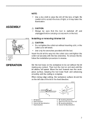
Base 2. Switch lever 001699 Switch action CAUTION: • Before plugging in the tool, always be sure that the tool is switched off. To turn it off. 6 ... sure that the tool is switched off and unplugged before adjusting or checking function on the lamp, move the switch lever to secure the tool base. 3 1. Possible to the I (ON) position. Adjusting roller 1 1. Move the switch lever to the "OFF" side to turn on the tool. 001698 Adjusting bit protrusion 1 To...
Base 2. Switch lever 001699 Switch action CAUTION: • Before plugging in the tool, always be sure that the tool is switched off. To turn it off. 6 ... sure that the tool is switched off and unplugged before adjusting or checking function on the lamp, move the switch lever to secure the tool base. 3 1. Possible to the I (ON) position. Adjusting roller 1 1. Move the switch lever to the "OFF" side to turn on the tool. 001698 Adjusting bit protrusion 1 To...
Owners Manual
Page 7
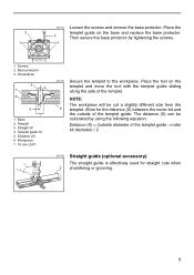
...the dirt off and unplugged before carrying out any contact. Tighten 3. Move the tool forward over the workpiece surface, keeping the tool base flush and advancing smoothly until the bit attains full speed. Correct bit feed direction 7. Insert the bit all the way into the ...securely with the tool. To remove the bit, follow the installation procedure in the feed direction. 001701 6 3 1 245 7 8 1. OPERATION Set the tool base on the tool. 1 2 3 1. When doing edge cutting, the workpiece surface should be sure that the tool is complete. Feed direction 5. Be careful ...
...the dirt off and unplugged before carrying out any contact. Tighten 3. Move the tool forward over the workpiece surface, keeping the tool base flush and advancing smoothly until the bit attains full speed. Correct bit feed direction 7. Insert the bit all the way into the ...securely with the tool. To remove the bit, follow the installation procedure in the feed direction. 001701 6 3 1 245 7 8 1. OPERATION Set the tool base on the tool. 1 2 3 1. When doing edge cutting, the workpiece surface should be sure that the tool is complete. Feed direction 5. Be careful ...
Owners Manual
Page 9
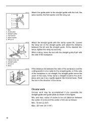
... 3. Place the 2 templet guide on the templet and move the tool with the templet guide sliding along the side of the templet. Base 2. Templet guide 10 5. Workpiece 7. 10 mm (3/8") 001705 Secure the templet to the workpiece. Distance (X) 6. router bit diameter) / 2 001706 Straight guide (optional accessory)...of the templet guide. NOTE: The workpiece will be calculated by tightening the screws. 1 1 1. Screwdriver 3 1 4 2 5 7 1. 001704 Loosen the screws and remove the base protector. Templet 3. The distance (X) can be cut a slightly different size from the 6 templet.
... 3. Place the 2 templet guide on the templet and move the tool with the templet guide sliding along the side of the templet. Base 2. Templet guide 10 5. Workpiece 7. 10 mm (3/8") 001705 Secure the templet to the workpiece. Distance (X) 6. router bit diameter) / 2 001706 Straight guide (optional accessory)...of the templet guide. NOTE: The workpiece will be calculated by tightening the screws. 1 1 1. Screwdriver 3 1 4 2 5 7 1. 001704 Loosen the screws and remove the base protector. Templet 3. The distance (X) can be cut a slightly different size from the 6 templet.
Owners Manual
Page 10
... too wide for the straight guide, or if the side of the arrow. Guide plate 3. Clamp screw (A) 2. Base (A) 001707 Attach the guide plate to the workpiece and use it as a guide against the trimmer base. At the desired distance, tighten the wing nut securely. Min. Straight guide 4. Straight guide 3. Loosen the wing...
... too wide for the straight guide, or if the side of the arrow. Guide plate 3. Clamp screw (A) 2. Base (A) 001707 Attach the guide plate to the workpiece and use it as a guide against the trimmer base. At the desired distance, tighten the wing nut securely. Min. Straight guide 4. Straight guide 3. Loosen the wing...
Owners Manual
Page 12
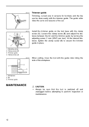
... in place. 3 1. Adjusting screw 2. Trimmer guide 4. Workpiece 2. The guide roller rides the curve and assures a fine cut. 001714 Install the trimmer guide on the tool base with the trimmer guide. At the desired dis- Clamp screw (B) 3. tance, tighten the clamp screw (B) to secure the trimmer guide in veneers for furniture and...
... in place. 3 1. Adjusting screw 2. Trimmer guide 4. Workpiece 2. The guide roller rides the curve and assures a fine cut. 001714 Install the trimmer guide on the tool base with the trimmer guide. At the desired dis- Clamp screw (B) 3. tance, tighten the clamp screw (B) to secure the trimmer guide in veneers for furniture and...
Owners Manual
Page 13
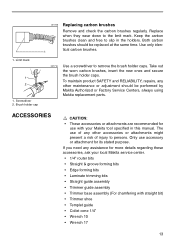
...• Wrench 17 13 ACCESSORIES CAUTION: • These accessories or attachments are recommended for more details regarding these accessories, ask your local Makita service center. • 1/4" router bits • Straight & groove forming bits • Edge forming bits • Laminate trimming bits ...• Straight guide assembly • Trimmer guide assembly • Trimmer base assembly (For chamfering with your Makita tool specified in the holders. 001145 Replacing carbon brushes Remove and check the carbon brushes regularly. Keep the ...
...• Wrench 17 13 ACCESSORIES CAUTION: • These accessories or attachments are recommended for more details regarding these accessories, ask your local Makita service center. • 1/4" router bits • Straight & groove forming bits • Edge forming bits • Laminate trimming bits ...• Straight guide assembly • Trimmer guide assembly • Trimmer base assembly (For chamfering with your Makita tool specified in the holders. 001145 Replacing carbon brushes Remove and check the carbon brushes regularly. Keep the ...

Owners Manual
Page 20
..., so the above limitation may also have been made or attempted by others: • repairs are : • lead from lead-based paints, • crystalline silica from bricks and cement and other masonry products, and • arsenic and chromium from chemically-treated lumber...., sawing, grinding, drilling, and other construction activities contains chemicals known to the State of California to filter out microscopic particles. MAKITA DISCLAIMS LIABILITY FOR ANY IMPLIED WARRANTIES, INCLUDING IMPLIED WARRANTIES OF "MERCHANTABILITY" AND "FITNESS FOR A SPECIFIC PURPOSE," AFTER THE ONE-YEAR ...
..., so the above limitation may also have been made or attempted by others: • repairs are : • lead from lead-based paints, • crystalline silica from bricks and cement and other masonry products, and • arsenic and chromium from chemically-treated lumber...., sawing, grinding, drilling, and other construction activities contains chemicals known to the State of California to filter out microscopic particles. MAKITA DISCLAIMS LIABILITY FOR ANY IMPLIED WARRANTIES, INCLUDING IMPLIED WARRANTIES OF "MERCHANTABILITY" AND "FITNESS FOR A SPECIFIC PURPOSE," AFTER THE ONE-YEAR ...
Parts Breakdown
Page 2
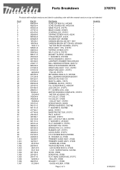
...ASS'Y 115V, 3707FC ARMATURE ASS'Y, 3707FC FAN 48, 3707FC RETAINING RING S-15, 5057KB BALL BEARING 6002DDW,BO5001 SWITCH, RD1100/1101 MAKITA LABEL, 3707fc TERMINAL BLOCK, 3707FC P.H. SCREW M4X12, 5201NA HOOK, 3700B SCREW M5, 3700B FLAT HEAD SCREW M5, 3707FC ROLLER, 3700B ROLLER...TRIMMER GUIDE ASS'Y, 3700B SCREW M6, 3700B THUM SCREW M6, 3700B CSH SCREW M4X10, 3700B C.S.H. WASHER 6, 5007NB BASE, 3707FC BASE PROTECTOR, 3707FC PIN 3, BJR181 ROLLER, 3707FC HEX. Parts Breakdown 3707FC Products with multiple versions are listed in subsiding order with the newest version on top not indented Fig # 1 ...
...ASS'Y 115V, 3707FC ARMATURE ASS'Y, 3707FC FAN 48, 3707FC RETAINING RING S-15, 5057KB BALL BEARING 6002DDW,BO5001 SWITCH, RD1100/1101 MAKITA LABEL, 3707fc TERMINAL BLOCK, 3707FC P.H. SCREW M4X12, 5201NA HOOK, 3700B SCREW M5, 3700B FLAT HEAD SCREW M5, 3707FC ROLLER, 3700B ROLLER...TRIMMER GUIDE ASS'Y, 3700B SCREW M6, 3700B THUM SCREW M6, 3700B CSH SCREW M4X10, 3700B C.S.H. WASHER 6, 5007NB BASE, 3707FC BASE PROTECTOR, 3707FC PIN 3, BJR181 ROLLER, 3707FC HEX. Parts Breakdown 3707FC Products with multiple versions are listed in subsiding order with the newest version on top not indented Fig # 1 ...


