
User Manual
Page 13
... Port LED Status Table 21 Audio Ports Configuration 21 Realtek HD Audio Manager 22 Overview of Components 24 CPU Socket ...26 DIMM Slots...27 PCI_E1~6: PCIe Expansion Slots 28 M2_1: M.2 Slot (Key M 29 SATA1~6: SATA 6Gb/s Connectors 30 JFP1, JFP2: Front Panel Connectors 30 CPU_PWR1, ATX_PWR1: Power Connectors 31 JCOM1: Serial Port Connector...
... Port LED Status Table 21 Audio Ports Configuration 21 Realtek HD Audio Manager 22 Overview of Components 24 CPU Socket ...26 DIMM Slots...27 PCI_E1~6: PCIe Expansion Slots 28 M2_1: M.2 Slot (Key M 29 SATA1~6: SATA 6Gb/s Connectors 30 JFP1, JFP2: Front Panel Connectors 30 CPU_PWR1, ATX_PWR1: Power Connectors 31 JCOM1: Serial Port Connector...
User Manual
Page 15
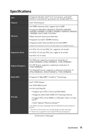
...slot (PCI_E4, supports x4 mode) y 4x PCIe 3.0 x1 slots... y 1x VGA port, supports a maximum resolution of 2048x1536@50Hz, 2048x1280@60Hz, 1920x1200@60Hz y 1x DVI-D port, supports a maximum resolution of 1920x1200@60Hz y 1x DisplayPort port, supports a maximum resolution of 4096x2304@24Hz, 3840x2160@60Hz, 1920x1200@60Hz Multi-GPU y Supports 2-Way AMD® CrossFire™ Technology Storage Intel® Z370... Chipset y 6x SATA 6Gb/s ports* y 1x M.2 slot...Slots Onboard...; Z370 Chipset y 4x DDR4 memory slots,...slot. ** The Turbo U.2 Host Card is not included, please purchase separately. ***...
...slot (PCI_E4, supports x4 mode) y 4x PCIe 3.0 x1 slots... y 1x VGA port, supports a maximum resolution of 2048x1536@50Hz, 2048x1280@60Hz, 1920x1200@60Hz y 1x DVI-D port, supports a maximum resolution of 1920x1200@60Hz y 1x DisplayPort port, supports a maximum resolution of 4096x2304@24Hz, 3840x2160@60Hz, 1920x1200@60Hz Multi-GPU y Supports 2-Way AMD® CrossFire™ Technology Storage Intel® Z370... Chipset y 6x SATA 6Gb/s ports* y 1x M.2 slot...Slots Onboard...; Z370 Chipset y 4x DDR4 memory slots,...slot. ** The Turbo U.2 Host Card is not included, please purchase separately. ***...

User Manual
Page 25
...Name Port Type CPU_FAN1,SYS_FAN1~4, PUMP_FAN1 Fan Connectors CPU_PWR1, ATX_PWR1 Power Connectors CPU Socket LGA1151 CPU Socket DIMMA1/ A2/ B1/ B2 DIMM Slots JAUD1 JBAT1 JCI1 Front Audio Connector Clear CMOS (Reset BIOS) Jumper Chassis Intrusion Connector JCOM1 Serial Port Connector JFP1, JFP2 Front Panel ... Port Connector Thunderbolt Add-on Card Connector TPM Module Connector JUSB1~2 USB 2.0 Connectors JUSB3~4 USB 3.1 Gen1 Connectors M2_1 M.2 Slot (Key M) PCI_E1~6 PCIe Expansion Slots SATA1~6 SATA 6Gb/s Connectors Page 34 31 26 27 35 37 35 31 30 36 37 36 32 32 29 28 ...
...Name Port Type CPU_FAN1,SYS_FAN1~4, PUMP_FAN1 Fan Connectors CPU_PWR1, ATX_PWR1 Power Connectors CPU Socket LGA1151 CPU Socket DIMMA1/ A2/ B1/ B2 DIMM Slots JAUD1 JBAT1 JCI1 Front Audio Connector Clear CMOS (Reset BIOS) Jumper Chassis Intrusion Connector JCOM1 Serial Port Connector JFP1, JFP2 Front Panel ... Port Connector Thunderbolt Add-on Card Connector TPM Module Connector JUSB1~2 USB 2.0 Connectors JUSB3~4 USB 3.1 Gen1 Connectors M2_1 M.2 Slot (Key M) PCI_E1~6 PCIe Expansion Slots SATA1~6 SATA 6Gb/s Connectors Page 34 31 26 27 35 37 35 31 30 36 37 36 32 32 29 28 ...
User Manual
Page 27
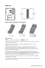
... if you want to install more efficient memory cooling system for 32-bit Windows OS due to BIOS and find the Memory Try It! DIMM Slots DIMMA1 DIMMB1 Channel A Channel B DIMMA2 Memory module installation recommendation DIMMB2 DIMMA2 DIMMB2 DIMMA2 DIMMB2 DIMMB1 DIMMA2 DIMMA1 Important y Always insert memory modules in the DIMMA2...
... if you want to install more efficient memory cooling system for 32-bit Windows OS due to BIOS and find the Memory Try It! DIMM Slots DIMMA1 DIMMB1 Channel A Channel B DIMMA2 Memory module installation recommendation DIMMB2 DIMMA2 DIMMB2 DIMMA2 DIMMB2 DIMMB1 DIMMA2 DIMMA1 Important y Always insert memory modules in the DIMMA2...

User Manual
Page 28
... Multiple graphics cards installation recommendation x16 x16 x4 Important y For a single PCIe x16 expansion card installation with optimum performance, using the PCI_E1 slot is recommended. y When adding or removing expansion cards, always turn off the power supply and unplug the power supply power cable from the...power outlet. Read the expansion card's documentation to prevent deformation of the slot. 28 Overview of Components y If you install a large and heavy graphics card, you need to use a tool such as MSI Gaming Series Graphics Card Bolster to support its weight and to check for...
... Multiple graphics cards installation recommendation x16 x16 x4 Important y For a single PCIe x16 expansion card installation with optimum performance, using the PCI_E1 slot is recommended. y When adding or removing expansion cards, always turn off the power supply and unplug the power supply power cable from the...power outlet. Read the expansion card's documentation to prevent deformation of the slot. 28 Overview of Components y If you install a large and heavy graphics card, you need to use a tool such as MSI Gaming Series Graphics Card Bolster to support its weight and to check for...

User Manual
Page 29
...://youtu.be/JCTFABytrYA Installing M.2 module 1. Insert your M.2 module. 4. Remove the base screw. 1 2 3. Remove the screw from the base screw. 2. Tighten the base screw into the M.2 slot at a 30-degree angle. 4 30° 5. Put the screw in the notch on the trailing edge of your M.2 module and tighten it into the base...
...://youtu.be/JCTFABytrYA Installing M.2 module 1. Insert your M.2 module. 4. Remove the base screw. 1 2 3. Remove the screw from the base screw. 2. Tighten the base screw into the M.2 slot at a 30-degree angle. 4 30° 5. Put the screw in the notch on the trailing edge of your M.2 module and tighten it into the base...

User Manual
Page 30
... connect to one SATA device. However, it is recommended that the flat connector be unavailable when an M.2 SATA SSD module has been installed in the M.2 slot. y SATA cables have identical plugs on the front panel. 2 10 JFP1 1 9 1 HDD LED + 2 Power LED + 3 HDD LED - 4 Power LED - 5 Reset Switch 6 Power Switch 7 Reset Switch...
... connect to one SATA device. However, it is recommended that the flat connector be unavailable when an M.2 SATA SSD module has been installed in the M.2 slot. y SATA cables have identical plugs on the front panel. 2 10 JFP1 1 9 1 HDD LED + 2 Power LED + 3 HDD LED - 4 Power LED - 5 Reset Switch 6 Power Switch 7 Reset Switch...

User Manual
Page 45
... enabled. [Enabled] Enables the Ipv4 PXE boot support. [Disabled] Disables the Ipv4 PXE boot support. fPCI Latency Timer [32] Sets latency timer of PCIe x16 slots for matching different installed devices. [Auto] This item will support Ipv4 protocol. It is only available if the system supports 64-bit PCI decoding. [Enabled...
... enabled. [Enabled] Enables the Ipv4 PXE boot support. [Disabled] Disables the Ipv4 PXE boot support. fPCI Latency Timer [32] Sets latency timer of PCIe x16 slots for matching different installed devices. [Auto] This item will support Ipv4 protocol. It is only available if the system supports 64-bit PCI decoding. [Enabled...
User Manual
Page 87
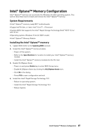
...BIOS (refer to install your Intel® Optane™ memory module. ˜ Install the Intel® Optane™ memory module into the M.2 slot. 3. Intel® Optane™ Memory Configuration 87 i Processor y System BIOS that supports the Intel® Rapid Storage Technology (Intel&#... system. ˜ Refer to the Specifications for location to the Updating BIOS section). 2. System Requirements y Intel® Optane™ memory ready MSI® motherboards y Supported 7th Gen, or later, Intel® Core™ - Enable M.2/Optane Genie ˜ Power on and press Delete ...
...BIOS (refer to install your Intel® Optane™ memory module. ˜ Install the Intel® Optane™ memory module into the M.2 slot. 3. Intel® Optane™ Memory Configuration 87 i Processor y System BIOS that supports the Intel® Rapid Storage Technology (Intel&#... system. ˜ Refer to the Specifications for location to the Updating BIOS section). 2. System Requirements y Intel® Optane™ memory ready MSI® motherboards y Supported 7th Gen, or later, Intel® Core™ - Enable M.2/Optane Genie ˜ Power on and press Delete ...

User Manual
Page 91
... graphics card. y Connect the AC power cord to bootup the system (Only for RMA repair, try to install only one memory module in the DIMMA2 slot first and then restart the computer. y Test with another known working y Make sure your got similar symptoms as mentioned below. y Test with another known working...
... graphics card. y Connect the AC power cord to bootup the system (Only for RMA repair, try to install only one memory module in the DIMMA2 slot first and then restart the computer. y Test with another known working y Make sure your got similar symptoms as mentioned below. y Test with another known working...


