User Guide
Page 5
... BIOS 2-2 Memory Speed/CPU FSB Support Matrix 2-2 DIMM Module Combination 2-2 Installing DDR Modules 2-3 Back Panel & Power Supply 2-4 Connectors, Jumpers and Slots 2-5 Chapter 3. Getting Started 1-1 Mainboard Specifications 1-2 Mainboard Layout 1-4 MSI Special Features 1-5 Color Management 1-5 D-Bracket™ 2 (Optional 1-6 Core Center 1-8 Core Cell™ Chip 1-10 LiveBIOS™ /Live Driver 1-11 Live Monitor 1-12 Round Cable...
... BIOS 2-2 Memory Speed/CPU FSB Support Matrix 2-2 DIMM Module Combination 2-2 Installing DDR Modules 2-3 Back Panel & Power Supply 2-4 Connectors, Jumpers and Slots 2-5 Chapter 3. Getting Started 1-1 Mainboard Specifications 1-2 Mainboard Layout 1-4 MSI Special Features 1-5 Color Management 1-5 D-Bracket™ 2 (Optional 1-6 Core Center 1-8 Core Cell™ Chip 1-10 LiveBIOS™ /Live Driver 1-11 Live Monitor 1-12 Round Cable...

User Guide
Page 7
Designed to fit the advanced AMD® Athlon™ , Athlon™ XP or Duron™ processors, the KT6V mainboard delivers a high performance and professional desktop platform solution. 1-1 The KT6V mainboard is based on VIA® KT600 North Bridge & VT8237 South Bridge chipset for purchasing KT6V (MS-7021 v1.X) ATX mainboard. Getting Started Getting Started Thank you for optimal system efficiency.
Designed to fit the advanced AMD® Athlon™ , Athlon™ XP or Duron™ processors, the KT6V mainboard delivers a high performance and professional desktop platform solution. 1-1 The KT6V mainboard is based on VIA® KT600 North Bridge & VT8237 South Bridge chipset for purchasing KT6V (MS-7021 v1.X) ATX mainboard. Getting Started Getting Started Thank you for optimal system efficiency.
User Guide
Page 8
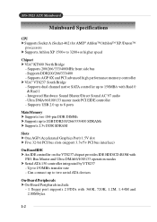
... up to 150MB/s with 360K, 720K, 1.2M, 1.44M and 2.88Mbytes 1-2 Can connect up to 3200+ or higher speed Chipset † VIA® KT600 North Bridge - MS-7021 ATX Mainboard Mainboard Specifications CPU † Supports Socket A (Socket-462) for AMD® Athlon™ /Athlon™ XP /Duron™ processors † Supports Athlon XP 1500+ to 2GB...
... up to 150MB/s with 360K, 720K, 1.2M, 1.44M and 2.88Mbytes 1-2 Can connect up to 3200+ or higher speed Chipset † VIA® KT600 North Bridge - MS-7021 ATX Mainboard Mainboard Specifications CPU † Supports Socket A (Socket-462) for AMD® Athlon™ /Athlon™ XP /Duron™ processors † Supports Athlon XP 1500+ to 2GB...

User Guide
Page 9
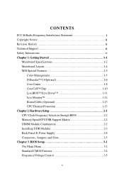
... provides "Plug & Play" BIOS which detects the peripheral devices and expansion cards of the board automatically. † The mainboard provides a Desktop Management Interface (DMI) function which records your mainboard specifications. Dimension †ATX Form Factor: 29.5 cm (L) x 20.5 cm (W) Mounting † 6 mounting holes Others † Suspend to RAM/Disk (S3/S4) †PC2001...
... provides "Plug & Play" BIOS which detects the peripheral devices and expansion cards of the board automatically. † The mainboard provides a Desktop Management Interface (DMI) function which records your mainboard specifications. Dimension †ATX Form Factor: 29.5 cm (L) x 20.5 cm (W) Mounting † 6 mounting holes Others † Suspend to RAM/Disk (S3/S4) †PC2001...
User Guide
Page 10
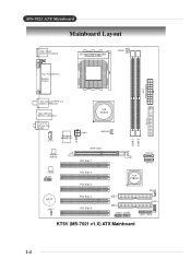
MS-7021 ATX Mainboard Mainboard Layout Top : mouse Bottom: keyboard SOCKET 462 CFAN1 Top : Parallel Port Bottom: COM A ATX Power Supply Top: Coaxial SPDIF Out Bottom: USB ports Top: LAN jack Bottom: USB ports VIA KT600 T:Line-In M: Line-Out B:Mic JCD1 Winbond W83697HF J6 JPW1 NBFAN1 AGP Slot Realtek 8201BL PCI Slot 1 DDR 1 DDR 2 FDD 1 SATA1 SATA2 Codec JAUD1 BATT + JBAT1 PCI Slot 2 PCI Slot 3 PCI Slot 4 PCI Slot 5 VIA VT8237 IDE 1 IDE 2 JUSB2 JUSB1 SFAN1 JLED1 JFP1 JFP2 KT6V (MS-7021 v1.X) ATX Mainboard 1-4
MS-7021 ATX Mainboard Mainboard Layout Top : mouse Bottom: keyboard SOCKET 462 CFAN1 Top : Parallel Port Bottom: COM A ATX Power Supply Top: Coaxial SPDIF Out Bottom: USB ports Top: LAN jack Bottom: USB ports VIA KT600 T:Line-In M: Line-Out B:Mic JCD1 Winbond W83697HF J6 JPW1 NBFAN1 AGP Slot Realtek 8201BL PCI Slot 1 DDR 1 DDR 2 FDD 1 SATA1 SATA2 Codec JAUD1 BATT + JBAT1 PCI Slot 2 PCI Slot 3 PCI Slot 4 PCI Slot 5 VIA VT8237 IDE 1 IDE 2 JUSB2 JUSB1 SFAN1 JLED1 JFP1 JFP2 KT6V (MS-7021 v1.X) ATX Mainboard 1-4

User Guide
Page 11
... Connectors Intel Spec IDE ATA133 Connectors Front Panel Connector JFP2 USB 2.0 Connectors Front Panel Connector JFP1 1-5 Getting Started MSI Special Features Color Management MSI has a unified color management rule for some connectors on the mainboards, which helps you to install the memory modules, expansion cards and other peripherals devices more easily and conveniently...
... Connectors Intel Spec IDE ATA133 Connectors Front Panel Connector JFP2 USB 2.0 Connectors Front Panel Connector JFP1 1-5 Getting Started MSI Special Features Color Management MSI has a unified color management rule for some connectors on the mainboards, which helps you to install the memory modules, expansion cards and other peripherals devices more easily and conveniently...
User Guide
Page 12
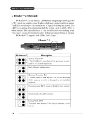
... combinations of signals to RAM for the overclocking users. The 4 LEDs can use graphic signal display to help users understand their system. Initializing Keyboard Controller. MS-7021 ATX Mainboard D-Bracket™ 2 (Optional) D-Bracket™ 2 is an external USB bracket integrating four Diagnostic LEDs, which use the feature to the screen. 1-6 D-Bracket™ 2 1 2 3 4 D-Bracket 2 Description...
... combinations of signals to RAM for the overclocking users. The 4 LEDs can use graphic signal display to help users understand their system. Initializing Keyboard Controller. MS-7021 ATX Mainboard D-Bracket™ 2 (Optional) D-Bracket™ 2 is an external USB bracket integrating four Diagnostic LEDs, which use the feature to the screen. 1-6 D-Bracket™ 2 1 2 3 4 D-Bracket 2 Description...
User Guide
Page 14
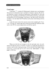
... Vcore, 3.3V, +5V and 12V. Including powerful function with hardware monitor, system alert and instinctive UI of overclocking, CoreCenter is advanced combination of CPU fan. 1-8 MS-7021 ATX Mainboard CoreCenter CoreCenter - (TM) contains OC Menu panel, wherein users can detect, view and adjust the PC hardware and system status during real time operation.
... Vcore, 3.3V, +5V and 12V. Including powerful function with hardware monitor, system alert and instinctive UI of overclocking, CoreCenter is advanced combination of CPU fan. 1-8 MS-7021 ATX Mainboard CoreCenter CoreCenter - (TM) contains OC Menu panel, wherein users can detect, view and adjust the PC hardware and system status during real time operation.

User Guide
Page 16
... PowerPro -- Cuts up to 50% of CoreCell™ Speedster -- method. Saves up to 65% power. -- capability. -- Greater O.C. MS-7021 ATX Mainboard Core CellTM Chip By diagnosing the current system utilization, the CoreCell™ Chip automatically tunes your motherboard to the optimal state, leading to less noise, longer duration, more powersaving and higher performance. Features of...
... PowerPro -- Cuts up to 50% of CoreCell™ Speedster -- method. Saves up to 65% power. -- capability. -- Greater O.C. MS-7021 ATX Mainboard Core CellTM Chip By diagnosing the current system utilization, the CoreCell™ Chip automatically tunes your motherboard to the optimal state, leading to less noise, longer duration, more powersaving and higher performance. Features of...
User Guide
Page 18
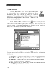
... will appear on the right) will appear. l View Last Result - l Preference - l FAQ - After installation, the "MSI Live Monitor" icon (as shown on the screen. Double click this icon to perform the functions listed below: l Auto Search - MS-7021 ATX Mainboard Live Monitor™ The Live Monitor™ is any. Configures the Search function, including the...
... will appear on the right) will appear. l View Last Result - l Preference - l FAQ - After installation, the "MSI Live Monitor" icon (as shown on the screen. Double click this icon to perform the functions listed below: l Auto Search - MS-7021 ATX Mainboard Live Monitor™ The Live Monitor™ is any. Configures the Search function, including the...

User Guide
Page 19
... disk drive connector (FDD1) and the other end to the slave drive. CPU Thermal Protection Aimed to prevent the CPU from overheating, MSI has developed a CPU Thermal Protection mechanism for AMD® CPU only. 1-13 Please note that this unique feature, users can better protect...CPU. Connect to the standard flooy disk. Connect to the system connectors on a thermal signal sensor. This CPU Thermal Protection mechanism works on the mainboard. It has the following benefits: † Data transfer rate started by 133MB/s † Backward compatibility (ATA33/66/100/133) † ...
... disk drive connector (FDD1) and the other end to the slave drive. CPU Thermal Protection Aimed to prevent the CPU from overheating, MSI has developed a CPU Thermal Protection mechanism for AMD® CPU only. 1-13 Please note that this unique feature, users can better protect...CPU. Connect to the standard flooy disk. Connect to the system connectors on a thermal signal sensor. This CPU Thermal Protection mechanism works on the mainboard. It has the following benefits: † Data transfer rate started by 133MB/s † Backward compatibility (ATA33/66/100/133) † ...

User Guide
Page 20
Hardware Setup Chapter 2. While doing the installation, be careful in holding the components and follow the installation procedures. 2-1 Also, it provides the instructions on the mainboard. Hardware Setup Hardware Setup This chapter tells you how to setup the connectors and jumpers on connecting the peripheral devices, such as the mouse, keyboard, etc.
Hardware Setup Chapter 2. While doing the installation, be careful in holding the components and follow the installation procedures. 2-1 Also, it provides the instructions on the mainboard. Hardware Setup Hardware Setup This chapter tells you how to setup the connectors and jumpers on connecting the peripheral devices, such as the mouse, keyboard, etc.
User Guide
Page 21
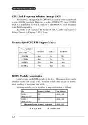
BIOS Setup. Memory modules can install either single- MS-7021 ATX Mainboard CPU Clock Frequency Selection through BIOS The hardware configuration for the installed CPU, refer to Frequency/ Voltage Control in any combination as follows: Slot Memory ... Yes DDR400 No Yes Yes Yes DIMM Module Combination Install at 133MHz when it is set the clock frequency for CPU clock frequency of the motherboard is installed on the slots. Therefore, to make a 133MHz CPU run at least one DIMM module on the board, you have to meet your own...
BIOS Setup. Memory modules can install either single- MS-7021 ATX Mainboard CPU Clock Frequency Selection through BIOS The hardware configuration for the installed CPU, refer to Frequency/ Voltage Control in any combination as follows: Slot Memory ... Yes DDR400 No Yes Yes Yes DIMM Module Combination Install at 133MHz when it is set the clock frequency for CPU clock frequency of the motherboard is installed on the slots. Therefore, to make a 133MHz CPU run at least one DIMM module on the board, you have to meet your own...

User Guide
Page 23
MS-7021 ATX Mainboard Back Panel & Power Supply The back panel provides the following connectors: Mouse Parallel SPDIF-Out LAN L-in L-out Keyboard COM A USB USB MIC ATX 20-Pin Power Connector: JWR1 This connector allows you to connect to the CPU. 10 20 3 4 1 2 JPW1 1 11 JWR1 JPW1 Pin Definition PIN SIGNAL 1 GND 2 ... 14 5 GND 15 6 5V 16 7 GND 17 8 PW_OK 18 9 5V_SB 19 10 12V 20 SIGNAL 3.3V -12V GND PS_ON GND GND GND -5V 5V 5V 2-4 ATX 12V Power Connector: JPW1 This 12V power connector is used to provide power to an...
MS-7021 ATX Mainboard Back Panel & Power Supply The back panel provides the following connectors: Mouse Parallel SPDIF-Out LAN L-in L-out Keyboard COM A USB USB MIC ATX 20-Pin Power Connector: JWR1 This connector allows you to connect to the CPU. 10 20 3 4 1 2 JPW1 1 11 JWR1 JPW1 Pin Definition PIN SIGNAL 1 GND 2 ... 14 5 GND 15 6 5V 16 7 GND 17 8 PW_OK 18 9 5V_SB 19 10 12V 20 SIGNAL 3.3V -12V GND PS_ON GND GND GND -5V 5V 5V 2-4 ATX 12V Power Connector: JPW1 This 12V power connector is used to provide power to an...

User Guide
Page 24
... CPU cooling fan. 2-5 Always consult the vendors for future BIOS) and other devices. Hardware Setup Connectors, Jumpers and Slots Floppy Disk Drive Connector: FDD1 The mainboard provides a standard floppy disk drive connector that provides PIO mode 0~4, Bus Master, and Ultra ATA66/100 function. FDD1 IDE1 IDE2 Hard Disk Connectors: IDE1 & IDE2...
... CPU cooling fan. 2-5 Always consult the vendors for future BIOS) and other devices. Hardware Setup Connectors, Jumpers and Slots Floppy Disk Drive Connector: FDD1 The mainboard provides a standard floppy disk drive connector that provides PIO mode 0~4, Bus Master, and Ultra ATA66/100 function. FDD1 IDE1 IDE2 Hard Disk Connectors: IDE1 & IDE2...
User Guide
Page 25
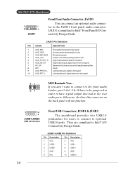
JAUD1 is compliant to front panel 6 AUD_RET_R Right channel audio signal return from front panel 95 10 6 MSI Reminds You... JAUD1 Pin Definition PIN SIGNAL DESCRIPTION 1 AUD_MIC Front panel microphone input signal 2 AUD_GND Ground used by analog audio ...10 AUD_RET_L Left channel audio signal return from front panel 7 HP_ON Reserved for users to connect to Intel® I /O Connectivity Design Guide. MS-7021 ATX Mainboard 9 1 10 2 JAUD1 Front Panel Audio Connector: JAUD1 You can connect an optional audio connector to the rear audio ports. They are compliant...
JAUD1 is compliant to front panel 6 AUD_RET_R Right channel audio signal return from front panel 95 10 6 MSI Reminds You... JAUD1 Pin Definition PIN SIGNAL DESCRIPTION 1 AUD_MIC Front panel microphone input signal 2 AUD_GND Ground used by analog audio ...10 AUD_RET_L Left channel audio signal return from front panel 7 HP_ON Reserved for users to connect to Intel® I /O Connectivity Design Guide. MS-7021 ATX Mainboard 9 1 10 2 JAUD1 Front Panel Audio Connector: JAUD1 You can connect an optional audio connector to the rear audio ports. They are compliant...

User Guide
Page 26
...-up Power Switch low reference pull-down to the front panel switches and LEDs. 2 10 1 9 JFP1 2 8 1 7 JFP2 Hardware Setup Front Panel Connectors: JFP1 & JFP2 The mainboard provides two front panel connectors for CD-ROM audio connectors. JFP1 is connected to a 2-pin chassis switch. R GND L JCD1 CD-In Connector: JCD1 The connectors...
...-up Power Switch low reference pull-down to the front panel switches and LEDs. 2 10 1 9 JFP1 2 8 1 7 JFP2 Hardware Setup Front Panel Connectors: JFP1 & JFP2 The mainboard provides two front panel connectors for CD-ROM audio connectors. JFP1 is connected to a 2-pin chassis switch. R GND L JCD1 CD-In Connector: JCD1 The connectors...
User Guide
Page 27
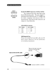
... GND 6 RXP MSI Reminds You... Optional Serial ATA cable Take out the dust cover and connect to the hard disk d evi c es Connect to 1 hard disk drive. The ports support 1st generation Serial ATA data rates of data may occur during transmission. MS-7021 ATX Mainboard SATA1 7 1... SATA2 Serial ATA HDD Connectors: SATA1, SATA2 The mainboard provides dual high-speed Serial ATA interface ports. Otherwise, the loss of 150MB/s and are fully ...
... GND 6 RXP MSI Reminds You... Optional Serial ATA cable Take out the dust cover and connect to the hard disk d evi c es Connect to 1 hard disk drive. The ports support 1st generation Serial ATA data rates of data may occur during transmission. MS-7021 ATX Mainboard SATA1 7 1... SATA2 Serial ATA HDD Connectors: SATA1, SATA2 The mainboard provides dual high-speed Serial ATA interface ports. Otherwise, the loss of 150MB/s and are fully ...

User Guide
Page 28
... combinations, please refer to D-Bracket™ 2 (Optional) in yellow color) LEDs 2-9 For definitions of LED signals. Hardware Setup 1 2 9 10 JLED1 D-Bracket™ 2 Connector: JLED1 The mainboard comes with a JLED1 connector for red color) 9 Key 10 NC Connected to JLED1 D-Bracket™ 2 Connected to JUSB1 (the USB pinheader in Chapter 1. JLED1 Pin...
... combinations, please refer to D-Bracket™ 2 (Optional) in yellow color) LEDs 2-9 For definitions of LED signals. Hardware Setup 1 2 9 10 JLED1 D-Bracket™ 2 Connector: JLED1 The mainboard comes with a JLED1 connector for red color) 9 Key 10 NC Connected to JLED1 D-Bracket™ 2 Connected to JUSB1 (the USB pinheader in Chapter 1. JLED1 Pin...
User Guide
Page 29
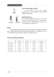
... shorting 2-3 pin while the system is on; Avoid clearing the CMOS while the system is off. Then return to restart the system. Slots The motherboard provides one AGP slot and five 32-bit Master PCI bus slots. PCI Interrupt Request Routing PCI Slot 1 PCI Slot 2 PCI Slot 3 PCI ... the AGP slot does not support 3.3V AGP card. Use of 3.3V AGP cards may result in a failure to 1-2 pin position. it will damage the mainboard. MS-7021 ATX Mainboard 1 3 JBAT1 Clear CMOS Jumper: JBAT1 If you want to clear the system configuration, use the JBAT1 (Clear CMOS Jumper) to clear data. 1 3 Keep ...
... shorting 2-3 pin while the system is on; Avoid clearing the CMOS while the system is off. Then return to restart the system. Slots The motherboard provides one AGP slot and five 32-bit Master PCI bus slots. PCI Interrupt Request Routing PCI Slot 1 PCI Slot 2 PCI Slot 3 PCI ... the AGP slot does not support 3.3V AGP card. Use of 3.3V AGP cards may result in a failure to 1-2 pin position. it will damage the mainboard. MS-7021 ATX Mainboard 1 3 JBAT1 Clear CMOS Jumper: JBAT1 If you want to clear the system configuration, use the JBAT1 (Clear CMOS Jumper) to clear data. 1 3 Keep ...


