User Manual
Page 13
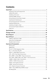
... Drives 9 Installing a Graphics Card 10 Connecting Peripheral Devices 11 Power On...12 Specifications...15 Package contents 20 Block Diagram ...21 Rear I/O Panel ...22 LAN Port LED Status Table 22 Audio Ports Configuration 22 Realtek Audio Console 23 Overview of Components 26 CPU Socket ...28 DIMM Slots...29 PCI_E1~5: PCIe Expansion Slots...~2: USB 2.0 Connectors 36 JAUD1: Front Audio Connector 37 JCOM1: Serial Port Connector 37 JCI1: Chassis Intrusion Connector 38 JBAT1: Clear CMOS (Reset BIOS) Jumper 39 EZ Debug LED...39 Contents 13
... Drives 9 Installing a Graphics Card 10 Connecting Peripheral Devices 11 Power On...12 Specifications...15 Package contents 20 Block Diagram ...21 Rear I/O Panel ...22 LAN Port LED Status Table 22 Audio Ports Configuration 22 Realtek Audio Console 23 Overview of Components 26 CPU Socket ...28 DIMM Slots...29 PCI_E1~5: PCIe Expansion Slots...~2: USB 2.0 Connectors 36 JAUD1: Front Audio Connector 37 JCOM1: Serial Port Connector 37 JCI1: Chassis Intrusion Connector 38 JBAT1: Clear CMOS (Reset BIOS) Jumper 39 EZ Debug LED...39 Contents 13
User Manual
Page 17
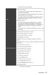
Continued from previous page y AMD® X570 Chipset ƒ 2x USB 3.2 Gen 2 (SuperSpeed USB 10Gbps) Type-A ports on the back panel ƒ 4x USB 3.2 Gen 1 (SuperSpeed USB) ports through the internal USB 3.2 ... audio connector y 2x System panel connectors y 1x TPM module connector y 1x Serial port connector y 1x Clear CMOS jumper y 1x Chassis Intrusion connector y 2x 4-pin RGB LED connectors y 2x 3-pin RAINBOW LED connectors y 4x EZ Debug LEDs Continued on next page Specifications 17
Continued from previous page y AMD® X570 Chipset ƒ 2x USB 3.2 Gen 2 (SuperSpeed USB 10Gbps) Type-A ports on the back panel ƒ 4x USB 3.2 Gen 1 (SuperSpeed USB) ports through the internal USB 3.2 ... audio connector y 2x System panel connectors y 1x TPM module connector y 1x Serial port connector y 1x Clear CMOS jumper y 1x Chassis Intrusion connector y 2x 4-pin RGB LED connectors y 2x 3-pin RAINBOW LED connectors y 4x EZ Debug LEDs Continued on next page Specifications 17
User Manual
Page 19
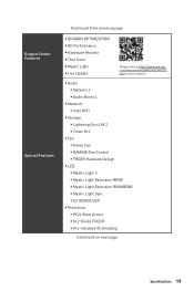
...://download.msi. com/manual/mb/DRAGONCENTER2. y Audio ƒ Nahimic 3 ƒ Audio Boost 4 y Network ƒ Intel WiFi y Storage ƒ Lightning Gen 4 M.2 ƒ Turbo M.2 y Fan ƒ Pump Fan ƒ GAMING Fan Control ƒ FROZR Heatsink Design y LED ƒ Mystic Light 3 ƒ Mystic Light Extension (RGB) ƒ Mystic Light Extension (RAINBOW) ƒ Mystic Light Sync ƒ EZ DEBUG LED y Protection...
...://download.msi. com/manual/mb/DRAGONCENTER2. y Audio ƒ Nahimic 3 ƒ Audio Boost 4 y Network ƒ Intel WiFi y Storage ƒ Lightning Gen 4 M.2 ƒ Turbo M.2 y Fan ƒ Pump Fan ƒ GAMING Fan Control ƒ FROZR Heatsink Design y LED ƒ Mystic Light 3 ƒ Mystic Light Extension (RGB) ƒ Mystic Light Extension (RAINBOW) ƒ Mystic Light Sync ƒ EZ DEBUG LED y Protection...
User Manual
Page 39
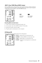
... computer. indicates DRAM is not detected or fail. indicates the booting device is not detected or fail. indicates CPU is not detected or fail. EZ Debug LED These LEDs indicate the debug status of Components 39 Power off the computer and unplug the power cord 2. JBAT1: Clear CMOS (Reset BIOS) Jumper There is CMOS memory...
... computer. indicates DRAM is not detected or fail. indicates the booting device is not detected or fail. indicates CPU is not detected or fail. EZ Debug LED These LEDs indicate the debug status of Components 39 Power off the computer and unplug the power cord 2. JBAT1: Clear CMOS (Reset BIOS) Jumper There is CMOS memory...


