User Guide
Page 2
... in order to comply with the emission limits. These limits are designed to comply with FCC Standard For Home or Office Use ii power cord, if any, must be required to correct the interference at his own expense. Notice 1 The changes or modifications not expressly ...of the FCC rules. Notice 2 Shielded interface cables and AC. VOIR LA NOTICE D'INSTALLATION AVANT DE RACCORDER AU RESEAU. Micro-Star International MEGA 651 Tested to provide reasonable protection against harmful interference when the equipment is likely to cause harmful interference, in which case the user will be...
... in order to comply with the emission limits. These limits are designed to comply with FCC Standard For Home or Office Use ii power cord, if any, must be required to correct the interference at his own expense. Notice 1 The changes or modifications not expressly ...of the FCC rules. Notice 2 Shielded interface cables and AC. VOIR LA NOTICE D'INSTALLATION AVANT DE RACCORDER AU RESEAU. Micro-Star International MEGA 651 Tested to provide reasonable protection against harmful interference when the equipment is likely to cause harmful interference, in which case the user will be...
User Guide
Page 4
...equipment should be noted. 10. The equipment has obvious sign of explosion if battery is damaged. - Do not place anything over the power cord. 8. DO NOT COVER THE OPENINGS. 6. Liquid has penetrated into the opening that people can not get the equipment checked by... The equipment has dropped and damaged. - Replace only with the same or equivalent type recommended by a service personnel: - Always Unplug the Power Cord before connecting the equipment to User's Manual. - Safety Instructions 1. Keep this equipment away from overheating. Keep this User's Manual for air...
...equipment should be noted. 10. The equipment has obvious sign of explosion if battery is damaged. - Do not place anything over the power cord. 8. DO NOT COVER THE OPENINGS. 6. Liquid has penetrated into the opening that people can not get the equipment checked by... The equipment has dropped and damaged. - Replace only with the same or equivalent type recommended by a service personnel: - Always Unplug the Power Cord before connecting the equipment to User's Manual. - Safety Instructions 1. Keep this equipment away from overheating. Keep this User's Manual for air...

User Guide
Page 6
... 1. Introducing Mainboard 2-1 Mainboard Layout 2-2 CPU/Memory 2-3 Introduction to DDR SDRAM 2-3 Power Supply 2-4 Front Panel 2-5 IEEE 1394 Port: J1394-2 2-5 IEEE 1394 Port: J1394-1 2-6 USB Ports 2-6 Mic-in/Head-Phone 2-7 OPTICAL SPDIF-in -One Feature Set 1-2 Front Panel 1-3 Back Panel 1-3 System Specification 1-4 Performance PC 1-6 Hi-Fi Audio 1-8 Home Theater 1-10 Chapter 2. Getting Started 1-1 All...
... 1. Introducing Mainboard 2-1 Mainboard Layout 2-2 CPU/Memory 2-3 Introduction to DDR SDRAM 2-3 Power Supply 2-4 Front Panel 2-5 IEEE 1394 Port: J1394-2 2-5 IEEE 1394 Port: J1394-1 2-6 USB Ports 2-6 Mic-in/Head-Phone 2-7 OPTICAL SPDIF-in -One Feature Set 1-2 Front Panel 1-3 Back Panel 1-3 System Specification 1-4 Performance PC 1-6 Hi-Fi Audio 1-8 Home Theater 1-10 Chapter 2. Getting Started 1-1 All...
User Guide
Page 7
...: CN10 2-13 CD-in PC Mode 3-12 Radio Mode 3-12 CD\MP Mode 3-13 Chapter 4: Setting BIOS Function 4-1 Entering Setup 4-2 Control Keys 4-2 Getting Help 4-3 Main Menu 4-3 Sub-Menu 4-3 General Help Using Audio Function 3-1 Introduction 3-2 Control Panel 3-3 Remote Controller 3-4 AC Power on 3-5 Playing CD/MP3 in...Mode 3-10 Using Audio Function in Connector: CN16 2-14 TV-Tuner Card Connector: CN13 2-14 CPU Fan Connector: CN15 2-14 Front Panel Power Connector: CN4 2-15 USB Card Reader Connector: CN6 2-15 LCM Connector: CN18 2-16 Modem Module Connector: CN21 2-16 Jumper 2-17 ...
...: CN10 2-13 CD-in PC Mode 3-12 Radio Mode 3-12 CD\MP Mode 3-13 Chapter 4: Setting BIOS Function 4-1 Entering Setup 4-2 Control Keys 4-2 Getting Help 4-3 Main Menu 4-3 Sub-Menu 4-3 General Help Using Audio Function 3-1 Introduction 3-2 Control Panel 3-3 Remote Controller 3-4 AC Power on 3-5 Playing CD/MP3 in...Mode 3-10 Using Audio Function in Connector: CN16 2-14 TV-Tuner Card Connector: CN13 2-14 CPU Fan Connector: CN15 2-14 Front Panel Power Connector: CN4 2-15 USB Card Reader Connector: CN6 2-15 LCM Connector: CN18 2-16 Modem Module Connector: CN21 2-16 Jumper 2-17 ...
User Guide
Page 8
Standard CMOS Features 4-6 Advanced BIOS Features 4-8 Advanced Chipset Features 4-11 Integrated Peripherals 4-13 Power Management Setup 4-19 PNP/PCI Configurations 4-23 PC Health Status 4-25 Frequency/Voltage Control 4-26 Appendix. Using Mega Radio A-1 Listening to Radio A-2 Setting Memory Station A-6 Recording Music A-7 viii
Standard CMOS Features 4-6 Advanced BIOS Features 4-8 Advanced Chipset Features 4-11 Integrated Peripherals 4-13 Power Management Setup 4-19 PNP/PCI Configurations 4-23 PC Health Status 4-25 Frequency/Voltage Control 4-26 Appendix. Using Mega Radio A-1 Listening to Radio A-2 Setting Memory Station A-6 Recording Music A-7 viii

User Guide
Page 13
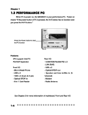
...in-one feature provides you with multiple functions in the front bezel. When PC is power on, you can use it for the feature: TV-out(option) 5.1 Channel Hi-Fi Power Switch TV-Tuner (Option) Optical Drive (Option) PC Power Switch Equalizer LCM Card Reader (Standard) FDD/2nd HDD (Option) MDC ...CD-RW) + PVR (TV Tuner) - See the following for Home Theater and Media Center PC. Home Theater: DVD+ 5.1 Channel - Completed PC: Office+ Game Machine 1-2 Hi-Fi Stereo: Audio CD+ MP3 Player+ AM/FM Tuner (power off , you can be set anywhere you want, such as bedroom or living room, while ...
...in-one feature provides you with multiple functions in the front bezel. When PC is power on, you can use it for the feature: TV-out(option) 5.1 Channel Hi-Fi Power Switch TV-Tuner (Option) Optical Drive (Option) PC Power Switch Equalizer LCM Card Reader (Standard) FDD/2nd HDD (Option) MDC ...CD-RW) + PVR (TV Tuner) - See the following for Home Theater and Media Center PC. Home Theater: DVD+ 5.1 Channel - Completed PC: Office+ Game Machine 1-2 Hi-Fi Stereo: Audio CD+ MP3 Player+ AM/FM Tuner (power off , you can be set anywhere you want, such as bedroom or living room, while ...

User Guide
Page 14
Front Panel Hi-Fi Power Switch IR Receiver Mode Eject/Stop Forward Play/Pause Backward Shuttle Controller PC Power Switch HDD LED PC Reset Getting Started Optical SPDIF-in J1394-2 Mic-in USB x 2 J1394-1 Head-Phone Back Panel Mouse Power Jack LAN Port Parallel Port Serial Port Radio Antenna Jack Modem Keyboard Lin-in VGA Port USB x 2 Speak-out PCI Slot Optical SPDIF-out AGP Slot Mic-in 1-3
Front Panel Hi-Fi Power Switch IR Receiver Mode Eject/Stop Forward Play/Pause Backward Shuttle Controller PC Power Switch HDD LED PC Reset Getting Started Optical SPDIF-in J1394-2 Mic-in USB x 2 J1394-1 Head-Phone Back Panel Mouse Power Jack LAN Port Parallel Port Serial Port Radio Antenna Jack Modem Keyboard Lin-in VGA Port USB x 2 Speak-out PCI Slot Optical SPDIF-out AGP Slot Mic-in 1-3

User Guide
Page 15
...Full Range Chassis: - 202(W) x 320(D) x 151(H) mm (9.76 Liters) 1-4 MS-8606 (Option PCI with Remote Controller) TV Tuner Function - SiS 651 + SiS 962 Memory: - Integrated (AGP 4X) ** On-Board VGA memory: None On-Board Communication - LAN: integrated in ALC 650, support 5.1 ...'97 Codec integrated in Realtek (10/100Mb) - RTL8801B PHY (2 ports), Front x 2 (4 pin, 6 pin) Expansion Slots: - PCI 2.2 x 1, AGP (4X) x1 Power Off Function: - Modem: 56K MDC module On-Board USB - Support Socket 478 for Card Reader & RF K/B, M/S (MFG Option) On-Board IEEE 1394: - MS-6760 (...
...Full Range Chassis: - 202(W) x 320(D) x 151(H) mm (9.76 Liters) 1-4 MS-8606 (Option PCI with Remote Controller) TV Tuner Function - SiS 651 + SiS 962 Memory: - Integrated (AGP 4X) ** On-Board VGA memory: None On-Board Communication - LAN: integrated in ALC 650, support 5.1 ...'97 Codec integrated in Realtek (10/100Mb) - RTL8801B PHY (2 ports), Front x 2 (4 pin, 6 pin) Expansion Slots: - PCI 2.2 x 1, AGP (4X) x1 Power Off Function: - Modem: 56K MDC module On-Board USB - Support Socket 478 for Card Reader & RF K/B, M/S (MFG Option) On-Board IEEE 1394: - MS-6760 (...

User Guide
Page 16
PC Alert System Hardware Monitor - LAN Wake Up Function - On-Board BlueBird Module for Power-Off features - Rear Panel: Parallel Port x 1, Serial Port x 1, VGA x 1, PS/2 x 2, Mic in/Line in /Headphone x 1, USB x 2, SPDIF/I x 1, 1394 x 1 (4-pin), 1394 x 1(6-pin) BIOS - 2MB Flash Others - Suspend to RAM/DISk function - Getting Started On-Board Headers & Connectors - Microsoft® PC 2001 - On-Board Equalizer (LCM) 1-5 Top Tech III (Thermal Overheat Protection Technology) - Front Panel: Mic in / Line out x 1, USB x 2, LAN (RJ45) x 1, SPDIF/O x 1, Modem (RJ11) x 1 -
PC Alert System Hardware Monitor - LAN Wake Up Function - On-Board BlueBird Module for Power-Off features - Rear Panel: Parallel Port x 1, Serial Port x 1, VGA x 1, PS/2 x 2, Mic in/Line in /Headphone x 1, USB x 2, SPDIF/I x 1, 1394 x 1 (4-pin), 1394 x 1(6-pin) BIOS - 2MB Flash Others - Suspend to RAM/DISk function - Getting Started On-Board Headers & Connectors - Microsoft® PC 2001 - On-Board Equalizer (LCM) 1-5 Top Tech III (Thermal Overheat Protection Technology) - Front Panel: Mic in / Line out x 1, USB x 2, LAN (RJ45) x 1, SPDIF/O x 1, Modem (RJ11) x 1 -
User Guide
Page 17
... has no function even you press the Hi-Fi button." Optical SPDIF-in - 6-in-1 Card Reader Rear I /O. 1-6 COM/VGA/Parallel/PS2 x 2 - Press the Power button to start the PC function Features CPU support: Intel P4 PCI/AGP Expansion Front I/O - Speaker-out/Line-in/Mic-in /Head-Phone - USB x 2 - 1394 x 2 (6-pin & 4-pin) - Chapter...
... has no function even you press the Hi-Fi button." Optical SPDIF-in - 6-in-1 Card Reader Rear I /O. 1-6 COM/VGA/Parallel/PS2 x 2 - Press the Power button to start the PC function Features CPU support: Intel P4 PCI/AGP Expansion Front I/O - Speaker-out/Line-in/Mic-in /Head-Phone - USB x 2 - 1394 x 2 (6-pin & 4-pin) - Chapter...

User Guide
Page 18
... MEGA651 uses two levels of machine from unveiled publicity and unauthorized access through BIOS control. The only way is to recover the system by pressing power button for 4 seconds. The Hi-Fi mode will deadly hang up. Storage Subsystem 1) Floppy (Standard Floppy & USB Floppy) 2) Hard Disk 3)...) In pure barebone Hi-Fi mode with NO CPU, Memory, Had Disk intalled, if you push the PC power button, the system will be malfunction. It's impossible to unplug power cord and reset the system. 1-7 Getting Started Target Operating System -- The security features protect the data of...
... MEGA651 uses two levels of machine from unveiled publicity and unauthorized access through BIOS control. The only way is to recover the system by pressing power button for 4 seconds. The Hi-Fi mode will deadly hang up. Storage Subsystem 1) Floppy (Standard Floppy & USB Floppy) 2) Hard Disk 3)...) In pure barebone Hi-Fi mode with NO CPU, Memory, Had Disk intalled, if you push the PC power button, the system will be malfunction. It's impossible to unplug power cord and reset the system. 1-7 Getting Started Target Operating System -- The security features protect the data of...

User Guide
Page 19
You can be used as a Hi-Fi audio. Power-off means "When used as a Hi-Fi audio, the PC should be in power-off , the MEGA651 can press the Hi-Fi button or use the audio function Features LCM Display, Clock, AM/FM Radio Tuner, Audio CD Play, ... See Chapter 3 for more information of using audio function. 1-8 Option 1 Press the Power button to use the audio function Option 2 Press the Hi-Fi button to use the remote controller to start the audio function. If you press the PC power button on, the Hi-Fi audio will be disabled ." Chapter 1 1.4 Hi-Fi...
You can be used as a Hi-Fi audio. Power-off means "When used as a Hi-Fi audio, the PC should be in power-off , the MEGA651 can press the Hi-Fi button or use the audio function Features LCM Display, Clock, AM/FM Radio Tuner, Audio CD Play, ... See Chapter 3 for more information of using audio function. 1-8 Option 1 Press the Power button to use the audio function Option 2 Press the Hi-Fi button to use the remote controller to start the audio function. If you press the PC power button on, the Hi-Fi audio will be disabled ." Chapter 1 1.4 Hi-Fi...

User Guide
Page 22
Introducing Mainboard 2 Introducing Mainboard 2.1 Mainboard Layout 2.2 CPU/Memory 2.3 Power Supply 2.4 Front Panel 2.5 Back Panel 2.6 Connectors 2.7 Jumper 2.8 Slots 2-1
Introducing Mainboard 2 Introducing Mainboard 2.1 Mainboard Layout 2.2 CPU/Memory 2.3 Power Supply 2.4 Front Panel 2.5 Back Panel 2.6 Connectors 2.7 Jumper 2.8 Slots 2-1

User Guide
Page 23
... J 1394-2 J 1394-1 US B1 IDE Connectors DDR DIMM Slots Modem Module Connector Power Supply Connector CN28 CN 2 0 CN26 SiS651 CN22 CN 2 3 S M BluebirdVL+ CN21 CN16 Realtek RTL8801B Realtek RTL8101L ATX Power Supply SiS962 CN12 CN10 CN15 CN13 AGP Slot Wi nb ond W83697HF Codec PCI Slot...Card Reader Connector Radio Module USB Connector Radio Antenna Connector LCM Connector Front Panel Power Connector AGP Slot Clear CMOS Jumper CPU Fan Connector ATX Power Supply PCI Slot TV Audio Connector CD-IN Connector Hi-Fi Power Connector To p : Parallel Port Bottom: SPDIF Line_Out L i ne _ ...
... J 1394-2 J 1394-1 US B1 IDE Connectors DDR DIMM Slots Modem Module Connector Power Supply Connector CN28 CN 2 0 CN26 SiS651 CN22 CN 2 3 S M BluebirdVL+ CN21 CN16 Realtek RTL8801B Realtek RTL8101L ATX Power Supply SiS962 CN12 CN10 CN15 CN13 AGP Slot Wi nb ond W83697HF Codec PCI Slot...Card Reader Connector Radio Module USB Connector Radio Antenna Connector LCM Connector Front Panel Power Connector AGP Slot Clear CMOS Jumper CPU Fan Connector ATX Power Supply PCI Slot TV Audio Connector CD-IN Connector Hi-Fi Power Connector To p : Parallel Port Bottom: SPDIF Line_Out L i ne _ ...

User Guide
Page 25
...16 GND 17 GND 18 19 5V 20 5V 1 11 20-Pin Connector CN20 Pin Definition PIN SINGAL 1 GND 2 GND 3 12V 4 12V 3 4 1 2 CN 20 Power Supply Specification Dimension PFC Wattage Electrical Design Specification Certificate 70 (H)x1450(W)x105(D) mm Yes (passive) 200W Max AC Output :100-127/200-240 VAC, Switch... :+5V 12A :+12V 13.5A :-12V 0.5A :+5Vsb 3A :+12Vsb 2.5A 80 mm PWM Fan FCC/UL/CUL/BSMI/CB/NEMKO/TUV 2-4 The power cord of power supply has been connected to the connectors on the mainboard. You can find two connectors (20-Piin & CN 20) on the mainboard when shipped...
...16 GND 17 GND 18 19 5V 20 5V 1 11 20-Pin Connector CN20 Pin Definition PIN SINGAL 1 GND 2 GND 3 12V 4 12V 3 4 1 2 CN 20 Power Supply Specification Dimension PFC Wattage Electrical Design Specification Certificate 70 (H)x1450(W)x105(D) mm Yes (passive) 200W Max AC Output :100-127/200-240 VAC, Switch... :+5V 12A :+12V 13.5A :-12V 0.5A :+5Vsb 3A :+12Vsb 2.5A 80 mm PWM Fan FCC/UL/CUL/BSMI/CB/NEMKO/TUV 2-4 The power cord of power supply has been connected to the connectors on the mainboard. You can find two connectors (20-Piin & CN 20) on the mainboard when shipped...
User Guide
Page 26
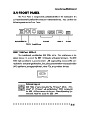
... IEEE 1394 Port: J1394-2 The mainboard provides two IEEE 1394 ports. It's connected to connect the IEEE 1394 device with external power. You can find the following ports on the mainboard. Software Support IEEE 1394 Driver is de- Just plug in the IEEE 1394 ...driver for a wide range of devices, including consumer electronics audio/video (A/V) appliances, storage peripherals, other PCs, and portable devices. This smaller one is provided by providing enhanced PC connectivity for IEEE 1394. 2-5 2.4 Front panel Introducing Mainboard The Front Panel is independent and extended from ...
... IEEE 1394 Port: J1394-2 The mainboard provides two IEEE 1394 ports. It's connected to connect the IEEE 1394 device with external power. You can find the following ports on the mainboard. Software Support IEEE 1394 Driver is de- Just plug in the IEEE 1394 ...driver for a wide range of devices, including consumer electronics audio/video (A/V) appliances, storage peripherals, other PCs, and portable devices. This smaller one is provided by providing enhanced PC connectivity for IEEE 1394. 2-5 2.4 Front panel Introducing Mainboard The Front Panel is independent and extended from ...

User Guide
Page 27
You can provide the power for attaching USB devices such as keyboard, mouse or other USB-compatible devices. Chapter 2 IEEE 1394 Port: J1394-1 The bigger 6-pin IEEE 1394 Port on ... 2-6 USB Ports The mainboard provides an OHCI (Universal Host Controller Interface) Universal Serial Bus root for the devices connected to IEEE 1394 devices without external power.
You can provide the power for attaching USB devices such as keyboard, mouse or other USB-compatible devices. Chapter 2 IEEE 1394 Port: J1394-1 The bigger 6-pin IEEE 1394 Port on ... 2-6 USB Ports The mainboard provides an OHCI (Universal Host Controller Interface) Universal Serial Bus root for the devices connected to IEEE 1394 devices without external power.

User Guide
Page 30
... DB 15-Pin Female Connector Pin Definition Analog Video Display Connector (DB-15s) PIN SIGNAL DESCRIPTION 1 Red 2 Green 3 Blue 4 Not used 5 Ground 6 Ground 7 Ground 8 Ground 9 Power 10 Ground 11 Not used 12 SDA 13 Horizontal Sync 14 Vertical Sync 15 SCL Mouse/Keyboard Connectors The mainboard provides two standard mini DIN...
... DB 15-Pin Female Connector Pin Definition Analog Video Display Connector (DB-15s) PIN SIGNAL DESCRIPTION 1 Red 2 Green 3 Blue 4 Not used 5 Ground 6 Ground 7 Ground 8 Ground 9 Power 10 Ground 11 Not used 12 SDA 13 Horizontal Sync 14 Vertical Sync 15 SCL Mouse/Keyboard Connectors The mainboard provides two standard mini DIN...

User Guide
Page 36
... to the Front Panel switches and LEDs. CN4 is compliant with Intel® Front Panel I/O Connectivity Design Guide. Front Panel Power Connector: CN4 Introducing Mainboard The mainboard provides a Front Panel connector for electrical connection to connect the USB Card Reader on the Front... Panel. 2-15 Do not use. HDD LED 12 Power LED Reset Switch Power Switch 9 10 CN4 CN4 Pin Definition PIN SIGNAL 1 HD_LED_P 2 FP PWR/SLP 3 HD_LED_N 4 FP PWR/SLP 5 RST_SW_N 6 PWR_SW_P...
... to the Front Panel switches and LEDs. CN4 is compliant with Intel® Front Panel I/O Connectivity Design Guide. Front Panel Power Connector: CN4 Introducing Mainboard The mainboard provides a Front Panel connector for electrical connection to connect the USB Card Reader on the Front... Panel. 2-15 Do not use. HDD LED 12 Power LED Reset Switch Power Switch 9 10 CN4 CN4 Pin Definition PIN SIGNAL 1 HD_LED_P 2 FP PWR/SLP 3 HD_LED_N 4 FP PWR/SLP 5 RST_SW_N 6 PWR_SW_P...

User Guide
Page 38
... system configuration, use the JBAT1 (Clear CMOS Jumper ) to 1-2 pin position. Avoid clearing the CMOS while the system is a CMOS RAM on board that has a power supply from external battery to clear the data: Clear CMOS Jumper: J2 1 1 3 Keep Data 3 Clear Data You can automatically boot OS every time it will...
... system configuration, use the JBAT1 (Clear CMOS Jumper ) to 1-2 pin position. Avoid clearing the CMOS while the system is a CMOS RAM on board that has a power supply from external battery to clear the data: Clear CMOS Jumper: J2 1 1 3 Keep Data 3 Clear Data You can automatically boot OS every time it will...