
User Guide
Page 6
CONTENTS Introduction Chapter 1. Introducing Mainboard 2-1 Mainboard Layout 2-2 CPU/Memory 2-3 Introduction to DDR SDRAM 2-3 Power Supply 2-4 Front Panel 2-5 IEEE 1394 Port: J1394-2 2-5 IEEE 1394 Port: J1394-1 2-6 USB Ports 2-6 Mic-in/Head-Phone 2-7 OPTICAL SPDIF-in -One Feature Set 1-2 Front Panel 1-3 Back Panel 1-3 System Specification 1-4 Performance PC 1-6 Hi-Fi Audio 1-8 Home Theater 1-10 Chapter 2. Getting Started...
CONTENTS Introduction Chapter 1. Introducing Mainboard 2-1 Mainboard Layout 2-2 CPU/Memory 2-3 Introduction to DDR SDRAM 2-3 Power Supply 2-4 Front Panel 2-5 IEEE 1394 Port: J1394-2 2-5 IEEE 1394 Port: J1394-1 2-6 USB Ports 2-6 Mic-in/Head-Phone 2-7 OPTICAL SPDIF-in -One Feature Set 1-2 Front Panel 1-3 Back Panel 1-3 System Specification 1-4 Performance PC 1-6 Hi-Fi Audio 1-8 Home Theater 1-10 Chapter 2. Getting Started...
User Guide
Page 17
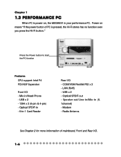
...USB x 2 - Optical SPDIF-out - Speaker-out/Line-in/Mic-in -1 Card Reader Rear I/O - Radio Antenna See Chapter 2 for more information of PC is your performance PC. Optical SPDIF-in - 6-in (5. 1channel) - Mic-in/Head-Phone - Power on , the MEGA651 is pressed, the Hi-Fi stereo has no ...function even you press the Hi-Fi button." Press the Power button to start the PC function Features CPU support: Intel P4 PCI/AGP Expansion Front I/O - LAN (RJ45) - Chapter 1 1.3 Performance PC When PC is power on means "If the power button of mainboard, Front and Rear I/O. 1-6 Modem -
...USB x 2 - Optical SPDIF-out - Speaker-out/Line-in/Mic-in -1 Card Reader Rear I/O - Radio Antenna See Chapter 2 for more information of PC is your performance PC. Optical SPDIF-in - 6-in (5. 1channel) - Mic-in/Head-Phone - Power on , the MEGA651 is pressed, the Hi-Fi stereo has no ...function even you press the Hi-Fi button." Press the Power button to start the PC function Features CPU support: Intel P4 PCI/AGP Expansion Front I/O - LAN (RJ45) - Chapter 1 1.3 Performance PC When PC is power on means "If the power button of mainboard, Front and Rear I/O. 1-6 Modem -

User Guide
Page 22
Introducing Mainboard 2 Introducing Mainboard 2.1 Mainboard Layout 2.2 CPU/Memory 2.3 Power Supply 2.4 Front Panel 2.5 Back Panel 2.6 Connectors 2.7 Jumper 2.8 Slots 2-1
Introducing Mainboard 2 Introducing Mainboard 2.1 Mainboard Layout 2.2 CPU/Memory 2.3 Power Supply 2.4 Front Panel 2.5 Back Panel 2.6 Connectors 2.7 Jumper 2.8 Slots 2-1

User Guide
Page 23
See the following for the mainboard layout: US B2 AUDIO2 J1 AUDIO1 CN1 J 1394-2 J 1394-1 US B1 IDE Connectors DDR DIMM Slots Modem Module Connector Power Supply Connector CN28 CN 2 0 CN26 ... p : Parallel Port Bottom: SPDIF Line_Out L i ne _ In Mic Top : mouse Bottom: keyboard Top: LAN Jack Bottom: USB ports Top : COM1 Bottom: VGA Port MS6760 v1.X Mainboard 2-2 Chapter 2 2.1 Mainboard layout The MEGA651 is equipped with MS6760 proprietary...
See the following for the mainboard layout: US B2 AUDIO2 J1 AUDIO1 CN1 J 1394-2 J 1394-1 US B1 IDE Connectors DDR DIMM Slots Modem Module Connector Power Supply Connector CN28 CN 2 0 CN26 ... p : Parallel Port Bottom: SPDIF Line_Out L i ne _ In Mic Top : mouse Bottom: keyboard Top: LAN Jack Bottom: USB ports Top : COM1 Bottom: VGA Port MS6760 v1.X Mainboard 2-2 Chapter 2 2.1 Mainboard layout The MEGA651 is equipped with MS6760 proprietary...

User Guide
Page 24
...PC2700/DDR333 or PC2100/DDR266 modules into the DDR DIMM slots (CN28/26). You can work properly to 2GB. The mainboard provides 2 slots for high performance PC, workstations and servers. It uses 2.5 volts as opposed to conventional SDRAM, but doubles the rate by SDR SDRAM. ... modules and supports the memory size up to protect the CPU from overheating. CN28 CN26 2-3 The mainboard uses a CPU socket called PGA478 for easy CPU installation. 2.2 CPU/memory Introducing Mainboard The MEGA651 supports Intel® Pentium® 4 processors in SDR SDRAM, and requires 184-pin ...
...PC2700/DDR333 or PC2100/DDR266 modules into the DDR DIMM slots (CN28/26). You can work properly to 2GB. The mainboard provides 2 slots for high performance PC, workstations and servers. It uses 2.5 volts as opposed to conventional SDRAM, but doubles the rate by SDR SDRAM. ... modules and supports the memory size up to protect the CPU from overheating. CN28 CN26 2-3 The mainboard uses a CPU socket called PGA478 for easy CPU installation. 2.2 CPU/memory Introducing Mainboard The MEGA651 supports Intel® Pentium® 4 processors in SDR SDRAM, and requires 184-pin ...

User Guide
Page 25
You can find two connectors (20-Piin & CN 20) on the mainboard when shipped out. ATX Power Supply Pin Definition PIN SINGAL PIN SIGNAL 10 20 1 3.3V 2 3.3V 3 GND 4 5V 5 GND 6 5V 7 GND 8 PW_OK 9 5V_SB 10 12V ... 80 mm PWM Fan FCC/UL/CUL/BSMI/CB/NEMKO/TUV 2-4 The power cord of power supply has been connected to the connectors on the mainboard. Chapter 2 2.3 Power Supply The system is equipped with a 200W(PFC) ATX power supply.
You can find two connectors (20-Piin & CN 20) on the mainboard when shipped out. ATX Power Supply Pin Definition PIN SINGAL PIN SIGNAL 10 20 1 3.3V 2 3.3V 3 GND 4 5V 5 GND 6 5V 7 GND 8 PW_OK 9 5V_SB 10 12V ... 80 mm PWM Fan FCC/UL/CUL/BSMI/CB/NEMKO/TUV 2-4 The power cord of power supply has been connected to the connectors on the mainboard. Chapter 2 2.3 Power Supply The system is equipped with a 200W(PFC) ATX power supply.
User Guide
Page 26
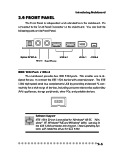
...port. These Operating Systems will install the driver for a wide range of devices, including consumer electronics audio/video (A/V) appliances, storage peripherals, other PCs, and portable devices. The IEEE 1394 high-speed serial bus complements USB by Windows® 98 SE, Windows® XP, Windows®...Optical SPDIF-In Mic-In Head-Phone USB x 2 J1394-1 J1394-2 IEEE 1394 Port: J1394-2 The mainboard provides two IEEE 1394 ports. You can find the following ports on the mainboard. It's connected to connect the IEEE 1394 device with external power. Software Support IEEE 1394 Driver is...
...port. These Operating Systems will install the driver for a wide range of devices, including consumer electronics audio/video (A/V) appliances, storage peripherals, other PCs, and portable devices. The IEEE 1394 high-speed serial bus complements USB by Windows® 98 SE, Windows® XP, Windows®...Optical SPDIF-In Mic-In Head-Phone USB x 2 J1394-1 J1394-2 IEEE 1394 Port: J1394-2 The mainboard provides two IEEE 1394 ports. You can find the following ports on the mainboard. It's connected to connect the IEEE 1394 device with external power. Software Support IEEE 1394 Driver is...

User Guide
Page 27
... directly into the port. These Operating Systems will install the driver for the devices connected to IEEE 1394 devices without external power. USB Ports The mainboard provides an OHCI (Universal Host Controller Interface) Universal Serial Bus root for you to connect to this port. You can provide the power for IEEE...
... directly into the port. These Operating Systems will install the driver for the devices connected to IEEE 1394 devices without external power. USB Ports The mainboard provides an OHCI (Universal Host Controller Interface) Universal Serial Bus root for you to connect to this port. You can provide the power for IEEE...

User Guide
Page 28
Head-Phone is developed jointly by the Sony and Philips corporations . OPTICAL SPDIF-in is a connector for microphone. The SPDIF (Sony & Philips Digital Interface) is a connector for Speakers or Headphones. A standard audio file transfer format, SPDIF allows the transfer of SPDIF interface for recording and playing. Introducing Mainboard Mic-in/Head-Phone Mic-in The OPTICAL connector allows you to receive the audio file of digital audio signals from one device to another without having to be converted first to an analog format. 2-7
Head-Phone is developed jointly by the Sony and Philips corporations . OPTICAL SPDIF-in is a connector for microphone. The SPDIF (Sony & Philips Digital Interface) is a connector for Speakers or Headphones. A standard audio file transfer format, SPDIF allows the transfer of SPDIF interface for recording and playing. Introducing Mainboard Mic-in/Head-Phone Mic-in The OPTICAL connector allows you to receive the audio file of digital audio signals from one device to another without having to be converted first to an analog format. 2-7

User Guide
Page 29
... following ports: Serial Port Mouse LAN Port Parallel Port VGA Port Keyboard USB x 2 Optical SPDIF-out Lin-in Mic-in Speak-out Serial Port The mainboard offers a 9-pin male DIN serial port . You can attach a serial mouse or other serial devices directly to the connector. 1 2 3 4 5 6 7 8 9 9-Pin Male DIN Connector Pin Definition...
... following ports: Serial Port Mouse LAN Port Parallel Port VGA Port Keyboard USB x 2 Optical SPDIF-out Lin-in Mic-in Speak-out Serial Port The mainboard offers a 9-pin male DIN serial port . You can attach a serial mouse or other serial devices directly to the connector. 1 2 3 4 5 6 7 8 9 9-Pin Male DIN Connector Pin Definition...

User Guide
Page 30
...5V 5 Keyboard Clock Keyboard clock 6 NC No connection 2-9 You can plug a PS/2® mouse or keyboard directly into the connector. VGA Port Introducing Mainboard The mainboard provides one DB 15-pin female connector to connect a VGA monitor. 5 1 15 11 DB 15-Pin Female Connector Pin Definition Analog Video Display Connector...Ground 7 Ground 8 Ground 9 Power 10 Ground 11 Not used 12 SDA 13 Horizontal Sync 14 Vertical Sync 15 SCL Mouse/Keyboard Connectors The mainboard provides two standard mini DIN connectors for attaching PS/2® mouse and keyboard.
...5V 5 Keyboard Clock Keyboard clock 6 NC No connection 2-9 You can plug a PS/2® mouse or keyboard directly into the connector. VGA Port Introducing Mainboard The mainboard provides one DB 15-pin female connector to connect a VGA monitor. 5 1 15 11 DB 15-Pin Female Connector Pin Definition Analog Video Display Connector...Ground 7 Ground 8 Ground 9 Power 10 Ground 11 Not used 12 SDA 13 Horizontal Sync 14 Vertical Sync 15 SCL Mouse/Keyboard Connectors The mainboard provides two standard mini DIN connectors for attaching PS/2® mouse and keyboard.

User Guide
Page 31
... Transmit Differential Pair Transmit Differential Pair Receive Differential Pair Not Used Not Used Receive Differential Pair Not Used Not Used USB Ports The mainboard provides an OHCI (Universal Host Controller Interface) Universal Serial Bus root for connection to Local Area Network (LAN). You can connect ...a network cable to play the audio file of SPDIF interface. Chapter 2 RJ45 LAN Jack The mainboard provides one standard RJ-45 jack for attaching USB devices such as keyboard, mouse or other USB-compatible devices. You can plug the...
... Transmit Differential Pair Transmit Differential Pair Receive Differential Pair Not Used Not Used Receive Differential Pair Not Used Not Used USB Ports The mainboard provides an OHCI (Universal Host Controller Interface) Universal Serial Bus root for connection to Local Area Network (LAN). You can connect ...a network cable to play the audio file of SPDIF interface. Chapter 2 RJ45 LAN Jack The mainboard provides one standard RJ-45 jack for attaching USB devices such as keyboard, mouse or other USB-compatible devices. You can plug the...

User Guide
Page 32
Introducing Mainboard Parallel Port The mainboard provides a 25-pin female centronic connector as LPT. A parallel port is a standard printer port that supports Enhanced Parallel Port (EPP) and Extended Capabilities Parallel Port (...
Introducing Mainboard Parallel Port The mainboard provides a 25-pin female centronic connector as LPT. A parallel port is a standard printer port that supports Enhanced Parallel Port (EPP) and Extended Capabilities Parallel Port (...

User Guide
Page 34
CN23 (Secondary IDE Connector) - CN22 CN23 If you install two hard disks on the mainboard allows you with a standard floppy disk drive connector that provides PIO mode 0~4, Bus Master, and Ultra DMA/33/66/100 function. Refer to Slave ...the hard disk documentation supplied by setting its jumper. CN22 (Primary IDE Connector) - FDD Connector: CN10 The mainboard provides you to connect to two IDE device. 2.6 Connectors Introducing Mainboard IDE Connectors: CN22 & CN23 The mainboard has a 32-bit Enhanced PCI IDE and Ultra DMA 33/66/100 controller that supports 1.44M floppy disk...
CN23 (Secondary IDE Connector) - CN22 CN23 If you install two hard disks on the mainboard allows you with a standard floppy disk drive connector that provides PIO mode 0~4, Bus Master, and Ultra DMA/33/66/100 function. Refer to Slave ...the hard disk documentation supplied by setting its jumper. CN22 (Primary IDE Connector) - FDD Connector: CN10 The mainboard provides you to connect to two IDE device. 2.6 Connectors Introducing Mainboard IDE Connectors: CN22 & CN23 The mainboard has a 32-bit Enhanced PCI IDE and Ultra DMA 33/66/100 controller that supports 1.44M floppy disk...

User Guide
Page 35
... Fan Connector: CN15 The CPU Fan connector supports system cooling fans with +12V that is controlled by PWM. CN16 TV-Tuner Card Connector: CN13 The mainboard provides the connector to GND. You can insert the TV-Tuner card into the PCI Slot 1. CN15 GND +12V SENSOR 2-14 L GND R JCD1 L GND R Chapter...
... Fan Connector: CN15 The CPU Fan connector supports system cooling fans with +12V that is controlled by PWM. CN16 TV-Tuner Card Connector: CN13 The mainboard provides the connector to GND. You can insert the TV-Tuner card into the PCI Slot 1. CN15 GND +12V SENSOR 2-14 L GND R JCD1 L GND R Chapter...

User Guide
Page 36
USB Card Reader Connector: CN6 The mainboard provides a connector to GND Reserved. CN4 is compliant with Intel® Front Panel I/O Connectivity Design Guide. HDD LED 12 Power LED Reset Switch Power Switch 9 ... pull-up Power Switch low reference pull-down to connect the USB Card Reader on the Front Panel. 2-15 Front Panel Power Connector: CN4 Introducing Mainboard The mainboard provides a Front Panel connector for electrical connection to the Front Panel switches and LEDs. Do not use.
USB Card Reader Connector: CN6 The mainboard provides a connector to GND Reserved. CN4 is compliant with Intel® Front Panel I/O Connectivity Design Guide. HDD LED 12 Power LED Reset Switch Power Switch 9 ... pull-up Power Switch low reference pull-down to connect the USB Card Reader on the Front Panel. 2-15 Front Panel Power Connector: CN4 Introducing Mainboard The mainboard provides a Front Panel connector for electrical connection to the Front Panel switches and LEDs. Do not use.

User Guide
Page 37
Chapter 2 LCM Connector: CN8 The connector is directly inserted into the connector without an extra cable. 2-16 CN 8 +12VSBY 2 VCC3SBY 1 Key (0-~5) GND GND IR GND VCC5SBY 26 SPI Bus CD_SMI VCC5 HDLED PWRBTNH FP_RST GND LED-BL 25 Modem Module Connector: CN21 The mainboard provides the connector to connect the LCM on the front panel. The modem module is used to connect the modem module.
Chapter 2 LCM Connector: CN8 The connector is directly inserted into the connector without an extra cable. 2-16 CN 8 +12VSBY 2 VCC3SBY 1 Key (0-~5) GND GND IR GND VCC5SBY 26 SPI Bus CD_SMI VCC5 HDLED PWRBTNH FP_RST GND LED-BL 25 Modem Module Connector: CN21 The mainboard provides the connector to connect the LCM on the front panel. The modem module is used to connect the modem module.

User Guide
Page 38
... the data: Clear CMOS Jumper: J2 1 1 3 Keep Data 3 Clear Data You can automatically boot OS every time it will damage the mainboard. 2-17 Then return to clear data. 2.7 Jumper Introducing Mainboard There is a CMOS RAM on . With the CMOS RAM, the system can clear CMOS by shorting 2-3 pin while the system is...
... the data: Clear CMOS Jumper: J2 1 1 3 Keep Data 3 Clear Data You can automatically boot OS every time it will damage the mainboard. 2-17 Then return to clear data. 2.7 Jumper Introducing Mainboard There is a CMOS RAM on . With the CMOS RAM, the system can clear CMOS by shorting 2-3 pin while the system is...

User Guide
Page 68
... be enabled; Disable the controller if you 're using any audio device. Setting options: Disabled, Auto. Setting options: Disabled, Enabled. SIS S/W Modem Auto allows the mainboard to detect whether a modem is detected, the onboard S/W modem controller will be enabled. If a modem is used. SIS 1394 Controller This item allows you need...
... be enabled; Disable the controller if you 're using any audio device. Setting options: Disabled, Auto. Setting options: Disabled, Enabled. SIS S/W Modem Auto allows the mainboard to detect whether a modem is detected, the onboard S/W modem controller will be enabled. If a modem is used. SIS 1394 Controller This item allows you need...