
User Manual
Page 17
...in . Continued from previous page Internal Connectors LED Features I/O Controller Hardware Monitor Form Factor BIOS Features ∙∙1x 24-pin ATX main power connector ∙∙2x 8-pin ATX 12V power connectors ∙∙6x SATA 6Gb/s connectors ∙∙3x M.2 slots (M-Key) ∙∙1x USB 3.2 ...Controller Chip ∙∙CPU/System temperature detection ∙∙CPU/System fan speed detection ∙∙CPU/System fan speed control ∙∙ATX Form Factor ∙∙12 in . (30.5 cm x 24.4 cm) ∙∙1x 256 Mb flash ∙∙UEFI AMI...
...in . Continued from previous page Internal Connectors LED Features I/O Controller Hardware Monitor Form Factor BIOS Features ∙∙1x 24-pin ATX main power connector ∙∙2x 8-pin ATX 12V power connectors ∙∙6x SATA 6Gb/s connectors ∙∙3x M.2 slots (M-Key) ∙∙1x USB 3.2 ...Controller Chip ∙∙CPU/System temperature detection ∙∙CPU/System fan speed detection ∙∙CPU/System fan speed control ∙∙ATX Form Factor ∙∙12 in . (30.5 cm x 24.4 cm) ∙∙1x 256 Mb flash ∙∙UEFI AMI...
User Manual
Page 36
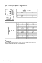
CPU_PWR1~3, ATX_PWR1: Power Connectors These connectors allow you to connect an ATX power supply. 8 5 CPU_PWR1~2 4 1 1 Ground 5 2 Ground 6 3 Ground 7 4 Ground 8 +12V +12V +12V +12V 1 +3.3V 13 2 +3.3V 14 3 Ground 15 12 24 4 +5V 16 5 Ground 17 6 +5V 18 ... PS-ON# Ground Ground Ground Res +5V +5V +5V Ground ⚠⚠Important Make sure that all the power cables are securely connected to a proper ATX power supply to ensure stable operation of the motherboard. 36 Overview of Components
CPU_PWR1~3, ATX_PWR1: Power Connectors These connectors allow you to connect an ATX power supply. 8 5 CPU_PWR1~2 4 1 1 Ground 5 2 Ground 6 3 Ground 7 4 Ground 8 +12V +12V +12V +12V 1 +3.3V 13 2 +3.3V 14 3 Ground 15 12 24 4 +5V 16 5 Ground 17 6 +5V 18 ... PS-ON# Ground Ground Ground Res +5V +5V +5V Ground ⚠⚠Important Make sure that all the power cables are securely connected to a proper ATX power supply to ensure stable operation of the motherboard. 36 Overview of Components
User Manual
Page 88
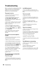
... if the power switch cable is connected to JFP1 pin header properly. ∙∙Verify the Clear CMOS jumper JBAT1 is set to lose all ATX power connectors like ATX_PWR1, CPU_PWR1 are properly illuminated. ∙∙Verify your TCP/IP settings. ∙∙Restart or reset your router. ∙∙Test...
... if the power switch cable is connected to JFP1 pin header properly. ∙∙Verify the Clear CMOS jumper JBAT1 is set to lose all ATX power connectors like ATX_PWR1, CPU_PWR1 are properly illuminated. ∙∙Verify your TCP/IP settings. ∙∙Restart or reset your router. ∙∙Test...


