
User Manual
Page 13
... 32 JTPM1: TPM Module Connector 32 JCOM1: Serial Port Connector 32 CPUFAN1~2,SYSFAN1~3: Fan Connectors 33 JLPT1: Parallel Port Connector 34 JBAT1: Clear CMOS (Reset BIOS) Jumper 34 JCI1: Chassis Intrusion Connector 35 Contents 13
... 32 JTPM1: TPM Module Connector 32 JCOM1: Serial Port Connector 32 CPUFAN1~2,SYSFAN1~3: Fan Connectors 33 JLPT1: Parallel Port Connector 34 JBAT1: Clear CMOS (Reset BIOS) Jumper 34 JCI1: Chassis Intrusion Connector 35 Contents 13
User Manual
Page 14
EZ Debug LED: Debug LED indicators 35 BIOS Setup...36 Entering BIOS Setup 36 Resetting BIOS 37 Updating BIOS...37 System Status Menu 38 Advanced Menu 39 Overclocking Menu 46 M-Flash Menu...52 Security Menu...53 Boot Menu...55 Save & Exit Menu 56 Software ...
EZ Debug LED: Debug LED indicators 35 BIOS Setup...36 Entering BIOS Setup 36 Resetting BIOS 37 Updating BIOS...37 System Status Menu 38 Advanced Menu 39 Overclocking Menu 46 M-Flash Menu...52 Security Menu...53 Boot Menu...55 Save & Exit Menu 56 Software ...

User Manual
Page 17
Continued from previous page Internal Connectors I/O Controller Hardware Monitor Form Factor BIOS Features ●● 1x 24-pin ATX main power connector ●● 1x 8-pin ATX 12V power connector ●● 6x SATA 6Gb/s connectors ●&#... speed control ●● ATX Form Factor ●● 12 in . (30.4 cm x 22.5 cm) ●● 1x 64 Mb flash ●● UEFI AMI BIOS ●● ACPI 5.0, PnP 1.0a, SM BIOS 2.8 ●● Multi-language Continued on next page Specifications 17 x 8.9 in .
Continued from previous page Internal Connectors I/O Controller Hardware Monitor Form Factor BIOS Features ●● 1x 24-pin ATX main power connector ●● 1x 8-pin ATX 12V power connector ●● 6x SATA 6Gb/s connectors ●&#... speed control ●● ATX Form Factor ●● 12 in . (30.4 cm x 22.5 cm) ●● 1x 64 Mb flash ●● UEFI AMI BIOS ●● ACPI 5.0, PnP 1.0a, SM BIOS 2.8 ●● Multi-language Continued on next page Specifications 17 x 8.9 in .
User Manual
Page 18
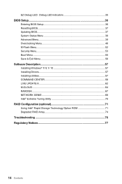
Software MSI Exclusive Features Specification Highlights Continued from previous...9679;● Google Chrome™ ,Google Toolbar, Google Drive ●● CPU-Z ●● CLICK BIOS ▶▶Hardware Monitor ●● COMMAND CENTER ▶▶System Monitor ▶▶Smart Fan Control ... Gen2 Ready (H170A PC MATE) ▶▶USB 3.1 Gen2 (10 Gb/s) Type-A Ready ●● SATA Express Support ●● Turbo M.2 Ready (H170A PC MATE) ●● NVMe / AHCI Driver Support (H170A PC MATE) ●● U.2 Support (Optional) (H170A PC MATE) ●●...
Software MSI Exclusive Features Specification Highlights Continued from previous...9679;● Google Chrome™ ,Google Toolbar, Google Drive ●● CPU-Z ●● CLICK BIOS ▶▶Hardware Monitor ●● COMMAND CENTER ▶▶System Monitor ▶▶Smart Fan Control ... Gen2 Ready (H170A PC MATE) ▶▶USB 3.1 Gen2 (10 Gb/s) Type-A Ready ●● SATA Express Support ●● Turbo M.2 Ready (H170A PC MATE) ●● NVMe / AHCI Driver Support (H170A PC MATE) ●● U.2 Support (Optional) (H170A PC MATE) ●●...
User Manual
Page 23
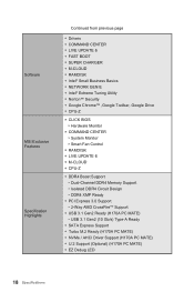
... JUSB1~2 JUSB3 M2_1 PCI_E1~5, PCI1~2 SATA1~6 SE1_21 Port Type Fan Connectors LGA1151 CPU Socket DIMM Slots Debug LED indicators Front Audio Connector Clear CMOS (Reset BIOS) Jumper Chassis Intrusion Connector Serial Port Connector Front Panel Connectors Parallel Port Connector Power Connectors TPM Module Connector USB 2.0 Connectors USB 3.1 Gen1 Connector M.2 Slot PCIe...
... JUSB1~2 JUSB3 M2_1 PCI_E1~5, PCI1~2 SATA1~6 SE1_21 Port Type Fan Connectors LGA1151 CPU Socket DIMM Slots Debug LED indicators Front Audio Connector Clear CMOS (Reset BIOS) Jumper Chassis Intrusion Connector Serial Port Connector Front Panel Connectors Parallel Port Connector Power Connectors TPM Module Connector USB 2.0 Connectors USB 3.1 Gen1 Connector M.2 Slot PCIe...

User Manual
Page 33
Voltage Mode fan connectors control fan speed by changing voltage. BIOS > Advanced > Hardware Monitor Command Center BIOS Hardware Monitor sub-menu allows you to adjust fan speed in relation to CPU temperature. The other is to go to set the temperature levels ... you plug a 3-pin (Non-PWM) fan to a PWM Mode fan connector, the fan speed will be always maintained at 100%, and that allow you to BIOS > Advanced > Hardware Monitor. COMMAND CENTER offers gradient points of Components 33 PWM Mode fan connectors provide constant 12V output and adjust fan speed with speed...
Voltage Mode fan connectors control fan speed by changing voltage. BIOS > Advanced > Hardware Monitor Command Center BIOS Hardware Monitor sub-menu allows you to adjust fan speed in relation to CPU temperature. The other is to go to set the temperature levels ... you plug a 3-pin (Non-PWM) fan to a PWM Mode fan connector, the fan speed will be always maintained at 100%, and that allow you to BIOS > Advanced > Hardware Monitor. COMMAND CENTER offers gradient points of Components 33 PWM Mode fan connectors provide constant 12V output and adjust fan speed with speed...
User Manual
Page 34
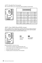
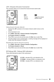
... 17 PRND7 18 Ground 19 ACK# 20 Ground 21 BUSY 22 Ground 23 PE 24 Ground 25 SLCT 26 No Pin JBAT1: Clear CMOS (Reset BIOS) Jumper There is CMOS memory onboard that is external powered from JBAT1. 4. Power off the computer and unplug the power cord 2. Remove the jumper cap... from a battery located on the computer. 34 Overview of Components Keep Data (default) Clear CMOS/ Reset BIOS Resetting BIOS to save system configuration data. Plug the power cord and power on the motherboard to default values 1.
... 17 PRND7 18 Ground 19 ACK# 20 Ground 21 BUSY 22 Ground 23 PE 24 Ground 25 SLCT 26 No Pin JBAT1: Clear CMOS (Reset BIOS) Jumper There is CMOS memory onboard that is external powered from JBAT1. 4. Power off the computer and unplug the power cord 2. Remove the jumper cap... from a battery located on the computer. 34 Overview of Components Keep Data (default) Clear CMOS/ Reset BIOS Resetting BIOS to save system configuration data. Plug the power cord and power on the motherboard to default values 1.
User Manual
Page 35
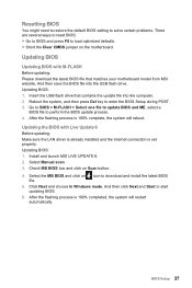
...save and exit and then press the Enter key to select Yes. 6. Resetting the chassis intrusion warning 1. VGA - Set Chassis Intrusion to BIOS > Security > Chassis Intrusion Configuration. 4. CPU - Go to Enabled. 5. DRAM - Go to connect the chassis intrusion switch cable. indicates.... Connect the JCI1 connector to Reset. 3. Close the chassis cover. 3. JCI1: Chassis Intrusion Connector This connector allows you to BIOS > Security > Chassis Intrusion Configuration. 2. Once the chassis cover is opened again, a warning message will be displayed on screen when...
...save and exit and then press the Enter key to select Yes. 6. Resetting the chassis intrusion warning 1. VGA - Set Chassis Intrusion to BIOS > Security > Chassis Intrusion Configuration. 4. CPU - Go to Enabled. 5. DRAM - Go to connect the chassis intrusion switch cable. indicates.... Connect the JCI1 connector to Reset. 3. Close the chassis cover. 3. JCI1: Chassis Intrusion Connector This connector allows you to BIOS > Security > Chassis Intrusion Configuration. 2. Once the chassis cover is opened again, a warning message will be displayed on screen when...

User Manual
Page 36
Click on the screen during the boot process. ●● Use MSI FAST BOOT application. Entering BIOS Setup Please refer the following methods to enter BIOS setup. ●● Press Delete key, when the Press DEL key to enter Setup Menu, F11 to USB flash drive (FAT/ FAT32 ... for reference only. You could also refer to avoid possible system damage or failure booting unless you purchased. The system will reboot and enter BIOS setup directly. Click on GO2BIOS ●● Enable the GO2BIOS item (Boot > GO2BIOS) in normal conditions. Function key Key Function Key ...
Click on the screen during the boot process. ●● Use MSI FAST BOOT application. Entering BIOS Setup Please refer the following methods to enter BIOS setup. ●● Press Delete key, when the Press DEL key to enter Setup Menu, F11 to USB flash drive (FAT/ FAT32 ... for reference only. You could also refer to avoid possible system damage or failure booting unless you purchased. The system will reboot and enter BIOS setup directly. Click on GO2BIOS ●● Enable the GO2BIOS item (Boot > GO2BIOS) in normal conditions. Function key Key Function Key ...
User Manual
Page 37
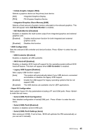
... the USB flash drive that matches your motherboard model from MSI website. Select Manual scan. 3. Check MB BIOS box and click on file. Click Next and choose In Windows mode. Install and launch MSI LIVE UPDATE 6. 2. Select the MB BIOS and click on Scan button. 4. Reboot the system, ...and then press Del key to download and install the latest BIOS 5. Go to BIOS > M-FLASH > Select one file to update BIOS and ME, select a BIOS file to start updating BIOS. 6. And then ...
... the USB flash drive that matches your motherboard model from MSI website. Select Manual scan. 3. Check MB BIOS box and click on file. Click Next and choose In Windows mode. Install and launch MSI LIVE UPDATE 6. 2. Select the MB BIOS and click on Scan button. 4. Reboot the system, ...and then press Del key to download and install the latest BIOS 5. Go to BIOS > M-FLASH > Select one file to update BIOS and ME, select a BIOS file to start updating BIOS. 6. And then ...

User Manual
Page 38
...cable connections of the device and motherboard. ▶▶System Information Shows detailed system information, including CPU type, BIOS version, and Memory (read only). ▶▶DMI Information Shows system information, desktop Board Information and chassis Information. (Read only). ...38 BIOS Setup The date from 1 to switch between time elements. The time format is displayed. Day of BIOS setup. ▶▶System Date Sets the system date. Use tab key to Sat,...
...cable connections of the device and motherboard. ▶▶System Information Shows detailed system information, including CPU type, BIOS version, and Memory (read only). ▶▶DMI Information Shows system information, desktop Board Information and chassis Information. (Read only). ...38 BIOS Setup The date from 1 to switch between time elements. The time format is displayed. Day of BIOS setup. ▶▶System Date Sets the system date. Use tab key to Sat,...

User Manual
Page 39
... to indicate the S3 state. ▶▶Integrated Peripherals Sets integrated peripherals' parameters, such as LAN, HDD, USB and audio. BIOS Setup 39 Press to set up the items of onboard power LED behaviors. Advanced Menu The Advanced Menu allows you to enter the ...Max Link Speed [Auto] Sets PCI Express protocol of PCIe x16 slots for matching different installed devices. [Auto] This item will be configured automatically by BIOS. [Gen1] Enables PCIe Gen1 support only. [Gen2] Enables PCIe Gen2 support only. [Gen3] Enables PCIe Gen3 support only. ▶▶PCI ...
... to indicate the S3 state. ▶▶Integrated Peripherals Sets integrated peripherals' parameters, such as LAN, HDD, USB and audio. BIOS Setup 39 Press to set up the items of onboard power LED behaviors. Advanced Menu The Advanced Menu allows you to enter the ...Max Link Speed [Auto] Sets PCI Express protocol of PCIe x16 slots for matching different installed devices. [Auto] This item will be configured automatically by BIOS. [Gen1] Enables PCIe Gen1 support only. [Gen2] Enables PCIe Gen2 support only. [Gen3] Enables PCIe Gen3 support only. ▶▶PCI ...

User Manual
Page 40
... disables the legacy network Boot Option ROM for SATA storage devices. ▶▶SATAx Hot Plug [Disabled] Allows user to enter the sub-menu. 40 BIOS Setup This item will appear when "Network Stack" is enabled. [Enabled] Enables the onboard LAN Boot ROM. [Disabled] Disables the onboard LAN Boot ROM. ▶...
... disables the legacy network Boot Option ROM for SATA storage devices. ▶▶SATAx Hot Plug [Disabled] Allows user to enter the sub-menu. 40 BIOS Setup This item will appear when "Network Stack" is enabled. [Enabled] Enables the onboard LAN Boot ROM. [Disabled] Disables the onboard LAN Boot ROM. ▶...
User Manual
Page 41
...[Auto] Sets serial port (COM). If set it manually. This item will optimize the IRQ automatically or you can set to Auto, BIOS will appear when IGD Multi-Monitor is connected and enables or disables the legacy USB support. [Enabled] Enable the USB support for legacy ... both integrated and external graphics cards. [Disabled] Disables this function. ▶▶USB Configuration Sets the onboard USB controller and device function. BIOS Setup 41 This item will appear when USB Controller is enabled. ▶▶Legacy USB Support [Enabled] Sets Legacy USB function support. [Auto...
...[Auto] Sets serial port (COM). If set it manually. This item will optimize the IRQ automatically or you can set to Auto, BIOS will appear when IGD Multi-Monitor is connected and enables or disables the legacy USB support. [Enabled] Enable the USB support for legacy ... both integrated and external graphics cards. [Disabled] Disables this function. ▶▶USB Configuration Sets the onboard USB controller and device function. BIOS Setup 41 This item will appear when USB Controller is enabled. ▶▶Legacy USB Support [Enabled] Sets Legacy USB function support. [Auto...

User Manual
Page 42
If set to Auto, BIOS will optimize the IRQ automatically or you can set it with a specific operating speed. When the temperature is over the maximum temperature, the fan will ... 1~4 target temperatures. These items will be un-available when Smart Fan Control is not detected or fail. [Disabled] Hides the CPU fan warning message. 42 BIOS Setup Press to enter the submenu. ▶▶Parallel (LPT) Port [Enabled] Enables or disables parallel(LPT) port. ▶▶Parallel (LPT) Port Settings [Auto...
If set to Auto, BIOS will optimize the IRQ automatically or you can set it with a specific operating speed. When the temperature is over the maximum temperature, the fan will ... 1~4 target temperatures. These items will be un-available when Smart Fan Control is not detected or fail. [Disabled] Hides the CPU fan warning message. 42 BIOS Setup Press to enter the submenu. ▶▶Parallel (LPT) Port [Enabled] Enables or disables parallel(LPT) port. ▶▶Parallel (LPT) Port Settings [Auto...

User Manual
Page 43
...10 WHQL Support [Disabled] Enables the supports for Windows 8.1/ 10 or disables for Entering BIOS Setup. ▶▶Power Management Setup Sets system Power Management of Fast Boot. [Enabled] Enables the MSI Fast Boot function to speed up the system after restoring AC power. [Last State] Restores... or disables the system power consumption according to EuP2013 regulation. [Enabled] Optimize the system power consumption according to enter BIOS setup if needed. BIOS Setup 43 Important When MSI Fast Boot is enabled, you can use FAST BOOT application to EuP 2013 regulation.
...10 WHQL Support [Disabled] Enables the supports for Windows 8.1/ 10 or disables for Entering BIOS Setup. ▶▶Power Management Setup Sets system Power Management of Fast Boot. [Enabled] Enables the MSI Fast Boot function to speed up the system after restoring AC power. [Last State] Restores... or disables the system power consumption according to EuP2013 regulation. [Enabled] Optimize the system power consumption according to enter BIOS setup if needed. BIOS Setup 43 Important When MSI Fast Boot is enabled, you can use FAST BOOT application to EuP 2013 regulation.

User Manual
Page 44
... this function. ▶▶Secure Boot Mode [Standard] Selects the secure boot mode. Press to enter the sub-menu. ▶▶Wake Up Event By [BIOS] Selects the wake up behaviors for Windows 8.1/ 10. This item is to select how the secure boot keys be available when... MSI Fast Boot is enabled. ▶▶Secure Boot Sets the Windows secure boot to configure the secure boot settings and manually load the secure keys. &#...
... this function. ▶▶Secure Boot Mode [Standard] Selects the secure boot mode. Press to enter the sub-menu. ▶▶Wake Up Event By [BIOS] Selects the wake up behaviors for Windows 8.1/ 10. This item is to select how the secure boot keys be available when... MSI Fast Boot is enabled. ▶▶Secure Boot Sets the Windows secure boot to configure the secure boot settings and manually load the secure keys. &#...

User Manual
Page 45
BIOS Setup 45 This item appears when you set to [Enabled], the system will automatically resume (boot up) on PS/2 keyboard is detected. [Disabled] Disables this ...
BIOS Setup 45 This item appears when you set to [Enabled], the system will automatically resume (boot up) on PS/2 keyboard is detected. [Disabled] Disables this ...
User Manual
Page 46
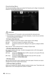
...;CPU Ratio [Auto] Sets the CPU ratio that support this function. ▶▶1/2/3/4-Core Ratio Limit [Auto] Allows you to configure in BIOS setup. Overclocking Menu The Overclocking Menu allows you to determine CPU clock speed. These items only appear when a CPU that is not guaranteed,... and if done improperly, it could void your warranty or severely damage your PC manually is only recommended for OC expert to adjust the frequency and voltage. Important ●● Overclocking your hardware. ▶▶OC ...
...;CPU Ratio [Auto] Sets the CPU ratio that support this function. ▶▶1/2/3/4-Core Ratio Limit [Auto] Allows you to configure in BIOS setup. Overclocking Menu The Overclocking Menu allows you to determine CPU clock speed. These items only appear when a CPU that is not guaranteed,... and if done improperly, it could void your warranty or severely damage your PC manually is only recommended for OC expert to adjust the frequency and voltage. Important ●● Overclocking your hardware. ▶▶OC ...
User Manual
Page 47
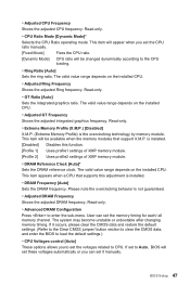
...Ring Ratio [Auto] Sets the ring ratio. User can set the memory timing for each/ all memory channel. If set to Auto, BIOS will be changed dynamically according to enter the sub-menu. This item will be available when the memory modules that supports this function. [...the DRAM reference clock. The valid value range depends on the installed CPU. The system may become unstable or unbootable after changing memory timing. BIOS Setup 47 is installed. [Disabled] Disables this adjustment is installed. ▶▶DRAM Frequency [Auto] Sets the DRAM frequency. If it...
...Ring Ratio [Auto] Sets the ring ratio. User can set the memory timing for each/ all memory channel. If set to Auto, BIOS will be changed dynamically according to enter the sub-menu. This item will be available when the memory modules that supports this function. [...the DRAM reference clock. The valid value range depends on the installed CPU. The system may become unstable or unbootable after changing memory timing. BIOS Setup 47 is installed. [Disabled] Disables this adjustment is installed. ▶▶DRAM Frequency [Auto] Sets the DRAM frequency. If it...


