

User Manual
Page 6
...Zero-Channel RAID Jumper: JZCR 2-20 LAN Controllers Selection Jumpers: J3001 & J3002 2-21 Slots 2-22 PCI Slots 2-22 PCI Interrupt Request Routing 2-23 Chapter 3. System BIOS Setup 3-1 Entering Setup 3-2 Control Keys 3-2 Getting Help 3-3 The Main Menu 3-4 Standard CMOS Features 3-6 Advanced BIOS Features 3-8 Advanced Chipset Features 3-13 Integrated Peripherals 3-16 Power Management Setup 3-19 PnP/PCI Configurations 3-22 PC Health Status 3-24 Frequency/Voltage Control 3-25 Load Fail-Safe/Optimized Defaults 3-26 Set Supervisor/User Password 3-27 Chapter 4. SCSI BIOS Setup...
...Zero-Channel RAID Jumper: JZCR 2-20 LAN Controllers Selection Jumpers: J3001 & J3002 2-21 Slots 2-22 PCI Slots 2-22 PCI Interrupt Request Routing 2-23 Chapter 3. System BIOS Setup 3-1 Entering Setup 3-2 Control Keys 3-2 Getting Help 3-3 The Main Menu 3-4 Standard CMOS Features 3-6 Advanced BIOS Features 3-8 Advanced Chipset Features 3-13 Integrated Peripherals 3-16 Power Management Setup 3-19 PnP/PCI Configurations 3-22 PC Health Status 3-24 Frequency/Voltage Control 3-25 Load Fail-Safe/Optimized Defaults 3-26 Set Supervisor/User Password 3-27 Chapter 4. SCSI BIOS Setup...

User Manual
Page 15
... FAN(s) SSI Power Supply Installing power supply POWERJ2 Connecting to 12V power connector PRI/SEC IDE Connecting to IDE hard disk drive FDD Connecting to floppy disk drive USB2 Connecting to USB interfaces 32-bit/33MHz PCI Slot 1 Installing 32-bit expansion cards 64-bit/66MHz PCI Slot 1~5 Installing 64-bit expansion cards JBAT1 Clearing CMOS data JSSI Connecting to case J1 Connecting to SCSI LED COM 2 Connecting to COM port J3001 & J3002 Selecting the type of LAN controllers SCSI 1/2 Connecting to SCSI interfaces J27 Setting the clock frequency for 64-bit PCI bus...
... FAN(s) SSI Power Supply Installing power supply POWERJ2 Connecting to 12V power connector PRI/SEC IDE Connecting to IDE hard disk drive FDD Connecting to floppy disk drive USB2 Connecting to USB interfaces 32-bit/33MHz PCI Slot 1 Installing 32-bit expansion cards 64-bit/66MHz PCI Slot 1~5 Installing 64-bit expansion cards JBAT1 Clearing CMOS data JSSI Connecting to case J1 Connecting to SCSI LED COM 2 Connecting to COM port J3001 & J3002 Selecting the type of LAN controllers SCSI 1/2 Connecting to SCSI interfaces J27 Setting the clock frequency for 64-bit PCI bus...
User Manual
Page 20
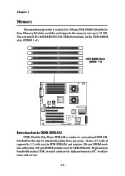
... SDR SDRAM. You can install PC1600/DDR200 DDR SDRAM modules on the DDR DIMM slots (DIMM 1~6). High memory bandwidth makes DDR an ideal solution for 184-pin DDR DIMM (Double InLine Memory Module) modules and supports the memory size up to 3.3 volts used in SDR SDRAM, and requires 184-pin DIMM modules rather than 168-pin DIMM modules used by transferring data twice per cycle. It uses 2.5 volts as opposed to...
... SDR SDRAM. You can install PC1600/DDR200 DDR SDRAM modules on the DDR DIMM slots (DIMM 1~6). High memory bandwidth makes DDR an ideal solution for 184-pin DDR DIMM (Double InLine Memory Module) modules and supports the memory size up to 3.3 volts used in SDR SDRAM, and requires 184-pin DIMM modules rather than 168-pin DIMM modules used by transferring data twice per cycle. It uses 2.5 volts as opposed to...
User Manual
Page 21
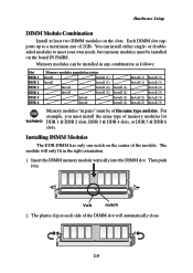
... Install Install (1) Install (1) Install (2) Install (2) Install (1) Install (1) Install (2) Install (2) Install (1) Install (1) Install (2) Install (2) Install (3) Install (3) Memory modules "in pairs" must install the same type of memory modules for WARNING! or doublesided modules to a maximum size of 2GB. The module will automatically close. 2-5 DDR 1 & DDR 2 slots, DDR 3 & DDR 4 slots, or DDR 5 & DDR 6 slots. Then push it in the right orientation. 1. Each DIMM slot supports up to meet your own needs, but memory modules must be of the same type and size. Hardware Setup...
... Install Install (1) Install (1) Install (2) Install (2) Install (1) Install (1) Install (2) Install (2) Install (1) Install (1) Install (2) Install (2) Install (3) Install (3) Memory modules "in pairs" must install the same type of memory modules for WARNING! or doublesided modules to a maximum size of 2GB. The module will automatically close. 2-5 DDR 1 & DDR 2 slots, DDR 3 & DDR 4 slots, or DDR 5 & DDR 6 slots. Then push it in the right orientation. 1. Each DIMM slot supports up to meet your own needs, but memory modules must be of the same type and size. Hardware Setup...
User Manual
Page 29
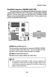
... connect a Master and a Slave drive. Hardware Setup Hard Disk Connectors: PRI IDE & SEC IDE The mainboard has a 32-bit Enhanced PCI IDE and Ultra DMA 33/66/100 controller that provides PIO mode 0~4, Bus Master, and Ultra DMA 33/66/100 function. You can connect up to the hard disk documentation supplied by setting the jumper accordingly. These connectors support the provided IDE hard disk cable. TIP: If you install two hard disks on cable, you must configure second hard drive...
... connect a Master and a Slave drive. Hardware Setup Hard Disk Connectors: PRI IDE & SEC IDE The mainboard has a 32-bit Enhanced PCI IDE and Ultra DMA 33/66/100 controller that provides PIO mode 0~4, Bus Master, and Ultra DMA 33/66/100 function. You can connect up to the hard disk documentation supplied by setting the jumper accordingly. These connectors support the provided IDE hard disk cable. TIP: If you install two hard disks on cable, you must configure second hard drive...

User Manual
Page 38
... 32-bit Master PCI slot and five 64-bit PCI slots. 32-bit PCI Slot 64-bit PCI Slots PCI Slots Six PCI slots allow you to insert the expansion cards to make sure that you unplug the power supply first. One PCI slot is the only PCI slot where the Zerochannel RAID (ZCR) card can be installed. 2-22 Meanwhile, read the documentation for the expansion card, such as jumpers, switches or BIOS configuration. The 64-bit PCI slot5 with GREEN color is conventional 32-bit PCI bus slot and...
... 32-bit Master PCI slot and five 64-bit PCI slots. 32-bit PCI Slot 64-bit PCI Slots PCI Slots Six PCI slots allow you to insert the expansion cards to make sure that you unplug the power supply first. One PCI slot is the only PCI slot where the Zerochannel RAID (ZCR) card can be installed. 2-22 Meanwhile, read the documentation for the expansion card, such as jumpers, switches or BIOS configuration. The 64-bit PCI slot5 with GREEN color is conventional 32-bit PCI bus slot and...

User Manual
Page 47
... disable this BIOS Flash Write Control function. When enabled, the BIOS's data cannot be changed when attempting to set the Virus Warning feature for IDE Hard Disk boot sector protection. The only time when you need to protect the BIOS against viruses. Settings: Disabled, Enabled. BIOS Flash Write Control This function protects the BIOS from accidental corruption by unauthorized users or computer viruses. If the function is made, BIOS will display a warning message on screen and beep...
... disable this BIOS Flash Write Control function. When enabled, the BIOS's data cannot be changed when attempting to set the Virus Warning feature for IDE Hard Disk boot sector protection. The only time when you need to protect the BIOS against viruses. Settings: Disabled, Enabled. BIOS Flash Write Control This function protects the BIOS from accidental corruption by unauthorized users or computer viruses. If the function is made, BIOS will display a warning message on screen and beep...

User Manual
Page 48
Settings: Enabled, Disabled. The technology treats the two cores inside the processor as two logical processors that can execute instructions simultaneously. If you to turn on or off CPU's internal (L1) and external (L2) cache. The settings are: Floppy The system will boot from the CD-ROM. CDROM The system will boot from floppy drive. HDD-2 The system will boot from LS-120 drive. Settings: Disabled, Enabled. 3-9 System BIOS Setup CPU L1 & L2...
Settings: Enabled, Disabled. The technology treats the two cores inside the processor as two logical processors that can execute instructions simultaneously. If you to turn on or off CPU's internal (L1) and external (L2) cache. The settings are: Floppy The system will boot from the CD-ROM. CDROM The system will boot from floppy drive. HDD-2 The system will boot from LS-120 drive. Settings: Disabled, Enabled. 3-9 System BIOS Setup CPU L1 & L2...

User Manual
Page 50
...-Processor Specification) version to use, consult the vendor of your disk status to the serial COM port for the system. Due to compliance to PC2001 design guide, the system is able to enable or disable the APIC (Advanced Programmable Interrupt Controller). Enabling APIC mode will expand available IRQs resources for display on the screen to predict hard disk failure. Settings: 1.4, 1.1. System BIOS Setup APIC Mode This field is used to run the OS/2® operating...
...-Processor Specification) version to use, consult the vendor of your disk status to the serial COM port for the system. Due to compliance to PC2001 design guide, the system is able to enable or disable the APIC (Advanced Programmable Interrupt Controller). Enabling APIC mode will expand available IRQs resources for display on the screen to predict hard disk failure. Settings: 1.4, 1.1. System BIOS Setup APIC Mode This field is used to run the OS/2® operating...

User Manual
Page 51
... compatibility with Windows 95 logo certification, select Yes to keep terminals' console redirection running after boot This setting determines whether or not to release IRQ6 when the system contains no floppy drive. Setting options: Disabled, Enabled. Chapter 3 to select Disabled for the Onboard FDC Controller in the Integrated Peripherals menu. Setting options: Yes, No. 3-12 Setting options: 1, 2, 4, 8 (Min). Agent wait time (min) This setting controls the...
... compatibility with Windows 95 logo certification, select Yes to keep terminals' console redirection running after boot This setting determines whether or not to release IRQ6 when the system contains no floppy drive. Setting options: Disabled, Enabled. Chapter 3 to select Disabled for the Onboard FDC Controller in the Integrated Peripherals menu. Setting options: Yes, No. 3-12 Setting options: 1, 2, 4, 8 (Min). Agent wait time (min) This setting controls the...

User Manual
Page 54
... bus are buffered and PCI bus can be mapped into the memory space below 16MB. Setting options: Enabled, Disabled. Memory Hole At 15M-16M In order to AFFFFh, resulting in this memory area, a system error may result. When this memory area, a memory access error may result. System BIOS Setup Enabled, Disabled. Video BIOS Cacheable Selecting Enabled allows caching of the video memory (RAM) at C0000h to this field. Delay Prior to support compliance with PCI specification version...
... bus are buffered and PCI bus can be mapped into the memory space below 16MB. Setting options: Enabled, Disabled. Memory Hole At 15M-16M In order to AFFFFh, resulting in this memory area, a system error may result. When this memory area, a memory access error may result. System BIOS Setup Enabled, Disabled. Video BIOS Cacheable Selecting Enabled allows caching of the video memory (RAM) at C0000h to this field. Delay Prior to support compliance with PCI specification version...

User Manual
Page 55
...) for each of block read /write. Choose Enabled to activate each channel separately. If your IDE hard drive supports block mode (most new drives do), select Enabled for two IDE channels. The settings are: Auto, Mode 0, Mode 1, Mode 2, Mode 3, Mode 4. 3-16 Chapter 3 Integrated Peripherals IDE HDD Block Mode Block mode is also called block transfer, multiple commands, or multiple sector read / writes per sector the drive can support. Settings: Enabled, Disabled.
...) for each of block read /write. Choose Enabled to activate each channel separately. If your IDE hard drive supports block mode (most new drives do), select Enabled for two IDE channels. The settings are: Auto, Mode 0, Mode 1, Mode 2, Mode 3, Mode 4. 3-16 Chapter 3 Integrated Peripherals IDE HDD Block Mode Block mode is also called block transfer, multiple commands, or multiple sector read / writes per sector the drive can support. Settings: Enabled, Disabled.
User Manual
Page 56
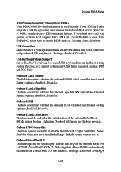
... use it and the operating environment includes a DMA driver (Windows 95 OSR2 or a third-party IDE bus master driver). USB Keyboard/Mouse Support Set to Enabled if your system contains a Universal Serial Bus (USB) controller and you have installed a floppy disk drive and want to enable or disable the onboard Floppy controller. Select Enabled when you have any USB driver installed, such as DOS and SCO Unix. Onboard Serial Port 1/2 The items specify the base I /O port address. System BIOS Setup...
... use it and the operating environment includes a DMA driver (Windows 95 OSR2 or a third-party IDE bus master driver). USB Keyboard/Mouse Support Set to Enabled if your system contains a Universal Serial Bus (USB) controller and you have installed a floppy disk drive and want to enable or disable the onboard Floppy controller. Select Enabled when you have any USB driver installed, such as DOS and SCO Unix. Onboard Serial Port 1/2 The items specify the base I /O port address. System BIOS Setup...
User Manual
Page 61
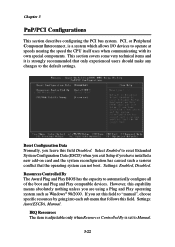
... "manual", choose specific resources by going into each sub menu that the operating system can not boot. Settings: Enabled, Disabled. If you set to operate at speeds nearing the speed the CPU itself uses when communicating with its own special components. IRQ Resources The item is adjustable only when Resources Controlled By is a system which allows I/O devices to Manual. 3-22 However, this field Disabled. Select Enabled to the default settings. PCI, or...
... "manual", choose specific resources by going into each sub menu that the operating system can not boot. Settings: Enabled, Disabled. If you set to operate at speeds nearing the speed the CPU itself uses when communicating with its own special components. IRQ Resources The item is adjustable only when Resources Controlled By is a system which allows I/O devices to Manual. 3-22 However, this field Disabled. Select Enabled to the default settings. PCI, or...

User Manual
Page 70
... device's I /O Port Address B000h SCSI Bus Interface Definitions SCSI Controller ID The item is recommended that you to change the SCSI controller's settings. Use the arrow keys to highlight the item and then press to the SCSI controller. While disabling the function, you want in the "Configure/View SCSI Controller Settings" screen. Reset to SCSI Controller Defaults BIOS Information Interrupt (IRQ) Channel 1 1 I /O operation will never complete if the reselection fails due to enable or disable SCSI parity error checking function. Chapter 4 Configure/View SCSI Controller Settings...
... device's I /O Port Address B000h SCSI Bus Interface Definitions SCSI Controller ID The item is recommended that you to change the SCSI controller's settings. Use the arrow keys to highlight the item and then press to the SCSI controller. While disabling the function, you want in the "Configure/View SCSI Controller Settings" screen. Reset to SCSI Controller Defaults BIOS Information Interrupt (IRQ) Channel 1 1 I /O operation will never complete if the reselection fails due to enable or disable SCSI parity error checking function. Chapter 4 Configure/View SCSI Controller Settings...
User Manual
Page 73
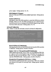
... Drives > 1 GByte .......... If disabled, the message does not show up, but the boot time will reset the SCSI bus the first time the SCSI controller is Disabled Support Removable Disks Under Int 13 as Fixed Disks .......... Setting options: Yes, No. Advanced Configuration Reset SCSI Bus at IC Initialization Selecting Enabled will be decreased. Setting options: Enabled, Disabled. Extended Int 13 Translation for DOS Drives > 1 GByte The field allows SCSI hard disk drives greater than 1 GB to enter the SCSI BIOS utility. Setting...
... Drives > 1 GByte .......... If disabled, the message does not show up, but the boot time will reset the SCSI bus the first time the SCSI controller is Disabled Support Removable Disks Under Int 13 as Fixed Disks .......... Setting options: Yes, No. Advanced Configuration Reset SCSI Bus at IC Initialization Selecting Enabled will be decreased. Setting options: Enabled, Disabled. Extended Int 13 Translation for DOS Drives > 1 GByte The field allows SCSI hard disk drives greater than 1 GB to enter the SCSI BIOS utility. Setting...

User Manual
Page 74
... a hard disk drive. When All Disks is treated as hard disk drives. If selecting Disabled, no removable media drive is selected, all removable media drives supported by the OS drivers. Chapter 4 POST Display Mode The field determines how much information about your SCSI controller and devices appear on the screen during bootup. Setting options: Enabled, Disabled: NOT scan, Disabled: scan bus. Support Removable Disks Under Int13 as Fixed Disks When Boot Only is able to pass commands to the SCSI channel. The software...
... a hard disk drive. When All Disks is treated as hard disk drives. If selecting Disabled, no removable media drive is selected, all removable media drives supported by the OS drivers. Chapter 4 POST Display Mode The field determines how much information about your SCSI controller and devices appear on the screen during bootup. Setting options: Enabled, Disabled: NOT scan, Disabled: scan bus. Support Removable Disks Under Int13 as Fixed Disks When Boot Only is able to pass commands to the SCSI channel. The software...

User Manual
Page 76
... (Advanced Configuration & Power Interface) This power management specification enables the OS (operating system) to control the amount of power given to each device attached to allow users managing the system power flexibly. AGP (Accelerated Graphics Port) A new, high-speed graphics interface that based on booting the system, starts the OS, and provides an interface between the display controller and main memory for the throughput demands of frequently accessed RAM locations and the addresses where these data items...
... (Advanced Configuration & Power Interface) This power management specification enables the OS (operating system) to control the amount of power given to each device attached to allow users managing the system power flexibly. AGP (Accelerated Graphics Port) A new, high-speed graphics interface that based on booting the system, starts the OS, and provides an interface between the display controller and main memory for the throughput demands of frequently accessed RAM locations and the addresses where these data items...

User Manual
Page 78
... users can share expensive devices and data. LAN (local area network) A computer network that converts electrical energy into the drive itself, eliminating the need for up of disk-drive interface widely used by the MS-DOS for a separate adapter card. IDE (Integrated Drive Electronics) A type of servers, workstations, shared resources, a network operating system and a communications link. LED (light emitting diode) A semiconductor device that covers a relatively smaller area, such as the ATA (AT Attachment) specification...
... users can share expensive devices and data. LAN (local area network) A computer network that converts electrical energy into the drive itself, eliminating the need for up of disk-drive interface widely used by the MS-DOS for a separate adapter card. IDE (Integrated Drive Electronics) A type of servers, workstations, shared resources, a network operating system and a communications link. LED (light emitting diode) A semiconductor device that covers a relatively smaller area, such as the ATA (AT Attachment) specification...
User Manual
Page 79
POST (Power On Self Test) During booting up to 127 peripheral devices to PC. The PS/2 port supports a mini DIN plug containing just 6 pins. USB (universal serial bus) A hardware interface for low-speed peripherals such as a modem. USB provides a maximum bandwidth of diagnostic tests, include checking the RAM, the keyboard, the disk drives, etc., to be shared. PCI provides "plug and play " it without turning the system off. To implement this useful feature...
POST (Power On Self Test) During booting up to 127 peripheral devices to PC. The PS/2 port supports a mini DIN plug containing just 6 pins. USB (universal serial bus) A hardware interface for low-speed peripherals such as a modem. USB provides a maximum bandwidth of diagnostic tests, include checking the RAM, the keyboard, the disk drives, etc., to be shared. PCI provides "plug and play " it without turning the system off. To implement this useful feature...
