
User Manual
Page 13
...2.0 Connectors 21 JTPM1: TPM Module Connector 21 CPU_FAN1, PUMP_FAN1, SYS_FAN1~3: Fan Connectors 22 JCI1: Chassis Intrusion Connector 23 JBAT1: Clear CMOS (Reset BIOS) Jumper 24 JCOM1: Serial Port Connector 24 JRGB1~2: RGB LED connector 25 JRAINBOW1~2: Addressable RGB LED connectors 26 EZ Debug LED...27 LED_SW1: EZ... LED Control 27 Installing OS, Drivers & Utilities 28 UEFI BIOS...29 BIOS Setup...30 Entering BIOS Setup 30 Resetting BIOS...31 Updating BIOS...31 EZ Mode...33 Advanced Mode ...36 OC Menu...37 Contents 1
...2.0 Connectors 21 JTPM1: TPM Module Connector 21 CPU_FAN1, PUMP_FAN1, SYS_FAN1~3: Fan Connectors 22 JCI1: Chassis Intrusion Connector 23 JBAT1: Clear CMOS (Reset BIOS) Jumper 24 JCOM1: Serial Port Connector 24 JRGB1~2: RGB LED connector 25 JRAINBOW1~2: Addressable RGB LED connectors 26 EZ Debug LED...27 LED_SW1: EZ... LED Control 27 Installing OS, Drivers & Utilities 28 UEFI BIOS...29 BIOS Setup...30 Entering BIOS Setup 30 Resetting BIOS...31 Updating BIOS...31 EZ Mode...33 Advanced Mode ...36 OC Menu...37 Contents 1
User Manual
Page 15
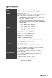
...Specifications CPU Chipset Memory Expansion Slot Onboard Graphics Supports AM4 socket 3rd Gen AMD Ryzen™ processors, and future AMD Ryzen™ processors with BIOS update AMD B550 Chipset ∙∙4x DDR4 memory slots, support up to 128GB* ▪▪Supports DDR4 1866/ 2133/ 2400/ ... architecture ∙∙Supports non-ECC UDIMM memory ∙∙Supports ECC UDIMM memory ∙∙Supports un-buffered memory * Please refer www.msi.com for more information on compatible memory. ∙∙1x PCIe 3.0/ 4.0 x16 slot (PCI_E1)* ∙∙2x PCIe 3.0 x1 slots ...
...Specifications CPU Chipset Memory Expansion Slot Onboard Graphics Supports AM4 socket 3rd Gen AMD Ryzen™ processors, and future AMD Ryzen™ processors with BIOS update AMD B550 Chipset ∙∙4x DDR4 memory slots, support up to 128GB* ▪▪Supports DDR4 1866/ 2133/ 2400/ ... architecture ∙∙Supports non-ECC UDIMM memory ∙∙Supports ECC UDIMM memory ∙∙Supports un-buffered memory * Please refer www.msi.com for more information on compatible memory. ∙∙1x PCIe 3.0/ 4.0 x16 slot (PCI_E1)* ∙∙2x PCIe 3.0 x1 slots ...

User Manual
Page 17
... Clear CMOS jumper LED Features ∙∙1x EZ LED Control switch ∙∙4x EZ Debug LED Back Panel Connectors ∙∙1x Flash BIOS Button ∙∙1x VGA port ∙∙1x Display port ∙∙1x HDMI port ∙∙4x USB 3.2 Gen 1 5Gbps Type-A ports ∙...
... Clear CMOS jumper LED Features ∙∙1x EZ LED Control switch ∙∙4x EZ Debug LED Back Panel Connectors ∙∙1x Flash BIOS Button ∙∙1x VGA port ∙∙1x Display port ∙∙1x HDMI port ∙∙4x USB 3.2 Gen 1 5Gbps Type-A ports ∙...

User Manual
Page 18
com/manual/mb/DRAGONCENTER2. Continued from previous page I/O Controller Hardware Monitor Form Factor BIOS Features Software Dragon Center Features NUVOTON NCT6687-R Controller Chip ∙∙CPU/ System/ Chipset temperature detection ∙∙CPU/ System/ ...(24.4 cm x 24.4 cm) ∙∙1x 256 Mb flash ∙∙UEFI AMI BIOS ∙∙ACPI 6.0, SMBIOS 2.8 ∙∙ Multi-language ∙∙ Drivers ∙∙DRAGON CENTER ∙∙CPU-Z MSI GAMING ∙∙Google Chrome™, Google Toolbar, Google Drive ∙∙Norton™ Internet...
com/manual/mb/DRAGONCENTER2. Continued from previous page I/O Controller Hardware Monitor Form Factor BIOS Features Software Dragon Center Features NUVOTON NCT6687-R Controller Chip ∙∙CPU/ System/ Chipset temperature detection ∙∙CPU/ System/ ...(24.4 cm x 24.4 cm) ∙∙1x 256 Mb flash ∙∙UEFI AMI BIOS ∙∙ACPI 6.0, SMBIOS 2.8 ∙∙ Multi-language ∙∙ Drivers ∙∙DRAGON CENTER ∙∙CPU-Z MSI GAMING ∙∙Google Chrome™, Google Toolbar, Google Drive ∙∙Norton™ Internet...

User Manual
Page 19
Special Features Continued from previous page ∙∙ Audio ▪▪Audio Boost ∙∙ Network ▪▪Intel WiFi ∙∙ Cooling ▪▪Pump Fan ▪▪Smart Fan Control ∙∙ LED ▪▪Mystic Light Extension (RAINBOW/RGB) ▪▪EZ ...;Core Boost ▪▪Front USB Type-C ∙∙ Protection ▪▪PCI-E Steel Armor ∙∙ Experience ▪▪Dragon Center ▪▪Click BIOS 5 ▪▪Flash BIOS Button Specifications 7
Special Features Continued from previous page ∙∙ Audio ▪▪Audio Boost ∙∙ Network ▪▪Intel WiFi ∙∙ Cooling ▪▪Pump Fan ▪▪Smart Fan Control ∙∙ LED ▪▪Mystic Light Extension (RAINBOW/RGB) ▪▪EZ ...;Core Boost ▪▪Front USB Type-C ∙∙ Protection ▪▪PCI-E Steel Armor ∙∙ Experience ▪▪Dragon Center ▪▪Click BIOS 5 ▪▪Flash BIOS Button Specifications 7

User Manual
Page 21
You can use it to change sound settings to page 32 for Updating BIOS with Flash BIOS Button. Rear I /O Panel 9 Please refer to get better sound experience. Application Enhancement Device Selection Connector Settings Jack Status Main Volume Rear I /O Panel PS/2... Wi-Fi Antenna connectors USB 3.2 Gen 1 (5Gbps) Type-A VGA 1 Gbps LAN Line-In Flash BIOS Button DisplayPort USB 2.0 Type-A Flash BIOS Port USB 3.2 Gen 1 (5Gbps) Type-A Mic-In Line-Out ∙∙ Flash BIOS Port/ Button - LAN Port LED Status Table Link/ Activity LED Status Off Yellow Blinking Description No link...
You can use it to change sound settings to page 32 for Updating BIOS with Flash BIOS Button. Rear I /O Panel 9 Please refer to get better sound experience. Application Enhancement Device Selection Connector Settings Jack Status Main Volume Rear I /O Panel PS/2... Wi-Fi Antenna connectors USB 3.2 Gen 1 (5Gbps) Type-A VGA 1 Gbps LAN Line-In Flash BIOS Button DisplayPort USB 2.0 Type-A Flash BIOS Port USB 3.2 Gen 1 (5Gbps) Type-A Mic-In Line-Out ∙∙ Flash BIOS Port/ Button - LAN Port LED Status Table Link/ Activity LED Status Off Yellow Blinking Description No link...
User Manual
Page 25
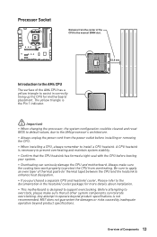
...with the CPU before installing or removing the CPU. ∙∙When installing a CPU, always remember to operate beyond product specifications. MSI® does not guarantee the damages or risks caused by inadequate operation beyond product specifications is the Pin 1 indicator. ⚠⚠...;Important ∙∙When changing the processor, the system configuration could be cleared and reset BIOS to default values, due to the AM4 processor's architecture. ∙∙Always unplug the power cord from overheating. Processor Socket ...
...with the CPU before installing or removing the CPU. ∙∙When installing a CPU, always remember to operate beyond product specifications. MSI® does not guarantee the damages or risks caused by inadequate operation beyond product specifications is the Pin 1 indicator. ⚠⚠...;Important ∙∙When changing the processor, the system configuration could be cleared and reset BIOS to default values, due to the AM4 processor's architecture. ∙∙Always unplug the power cord from overheating. Processor Socket ...

User Manual
Page 26
Go to BIOS and find the DRAM Frequency to set the memory frequency if you want to operate the memory at the marked or at a lower frequency than ... or overclocking. ∙∙The stability and compatibility of installed memory module depend on installed CPU and devices when overclocking. ∙∙Please refer www.msi.com for Dual channel mode, memory modules must be a little less than the amount of Components DIMM Slots DIMMA1 DIMMB1 Channel A Channel B DIMMA2 Memory module...
Go to BIOS and find the DRAM Frequency to set the memory frequency if you want to operate the memory at the marked or at a lower frequency than ... or overclocking. ∙∙The stability and compatibility of installed memory module depend on installed CPU and devices when overclocking. ∙∙Please refer www.msi.com for Dual channel mode, memory modules must be a little less than the amount of Components DIMM Slots DIMMA1 DIMMB1 Channel A Channel B DIMMA2 Memory module...

User Manual
Page 34
However, you to adjust fan speed in BIOS > HARDWARE MONITOR. current 2A 3A 1A Max. power 24W 36W 12W SYS_FAN3 SYS_FAN2 Switching fan mode and adjusting fan speed You can be classified as ...
However, you to adjust fan speed in BIOS > HARDWARE MONITOR. current 2A 3A 1A Max. power 24W 36W 12W SYS_FAN3 SYS_FAN2 Switching fan mode and adjusting fan speed You can be classified as ...

User Manual
Page 35
... connect the chassis intrusion switch cable. Go to Reset. 3. Resetting the chassis intrusion warning 1. Connect the JCI1 connector to select Yes. 6. Set Chassis Intrusion to BIOS > SETTINGS > Security > Chassis Intrusion Configuration. 4. Close the chassis cover. 3. Go to select Yes. Once the chassis cover is opened again, a warning message will be displayed... on screen when the computer is turned on the chassis. 2. Press F10 to save and exit and then press the Enter key to BIOS > SETTINGS > Security > Chassis Intrusion Configuration. 2.
... connect the chassis intrusion switch cable. Go to Reset. 3. Resetting the chassis intrusion warning 1. Connect the JCI1 connector to select Yes. 6. Set Chassis Intrusion to BIOS > SETTINGS > Security > Chassis Intrusion Configuration. 4. Close the chassis cover. 3. Go to select Yes. Once the chassis cover is opened again, a warning message will be displayed... on screen when the computer is turned on the chassis. 2. Press F10 to save and exit and then press the Enter key to BIOS > SETTINGS > Security > Chassis Intrusion Configuration. 2.

User Manual
Page 36
... motherboard to short JBAT1 for about 5-10 seconds. 3. Power off the computer and unplug the power cord. 2. Keep Data (default) Clear CMOS/ Reset BIOS Resetting BIOS to connect the optional serial port with bracket. 2 10 1 9 1 DCD 2 SIN 3 SOUT 4 DTR 5 Ground 6 DSR 7 RTS 8 CTS... 9 RI 10 No Pin 24 Overview of Components JBAT1: Clear CMOS (Reset BIOS) Jumper There is CMOS memory onboard that is external powered from JBAT1. 4. Remove the jumper cap from a battery located on the computer. Use a jumper ...
... motherboard to short JBAT1 for about 5-10 seconds. 3. Power off the computer and unplug the power cord. 2. Keep Data (default) Clear CMOS/ Reset BIOS Resetting BIOS to connect the optional serial port with bracket. 2 10 1 9 1 DCD 2 SIN 3 SOUT 4 DTR 5 Ground 6 DSR 7 RTS 8 CTS... 9 RI 10 No Pin 24 Overview of Components JBAT1: Clear CMOS (Reset BIOS) Jumper There is CMOS memory onboard that is external powered from JBAT1. 4. Remove the jumper cap from a battery located on the computer. Use a jumper ...

User Manual
Page 41
...32-bit Windows operating system - The MSI UEFI BIOS uses UEFI as the default boot mode to UEFI BIOS unless otherwise noted. After entering the BIOS, find the BIOS Mode at the top of the new chipset's capabilities. UEFI BIOS MSI UEFI BIOS is no malware tampers with the startup... (GPT). ∙∙Supports unlimited number of partitions. ∙∙Supports full capabilities of the operating system to ensure that traditional BIOS cannot achieve, and it still has a CSM (Compatibility Support Module) mode to replace legacy devices with older devices. UEFI advantages &#...
...32-bit Windows operating system - The MSI UEFI BIOS uses UEFI as the default boot mode to UEFI BIOS unless otherwise noted. After entering the BIOS, find the BIOS Mode at the top of the new chipset's capabilities. UEFI BIOS MSI UEFI BIOS is no malware tampers with the startup... (GPT). ∙∙Supports unlimited number of partitions. ∙∙Supports full capabilities of the operating system to ensure that traditional BIOS cannot achieve, and it still has a CSM (Compatibility Support Module) mode to replace legacy devices with older devices. UEFI advantages &#...

User Manual
Page 42
...avoid possible system damage or failure booting unless you are familiar with the processor. You could also refer to confirm your choice. 30 UEFI BIOS Function key F1: General Help list F2: Add/ Remove a favorite item F3: Enter Favorites menu F4: Enter CPU Specifications menu F5: ...chapter are for reference only and may be slightly different from the product you purchased. ∙∙The BIOS items will vary with BIOS. ⚠⚠Important ∙∙BIOS items are continuously update for better system performance. Select between Advanced mode and EZ mode F8: Load ...
...avoid possible system damage or failure booting unless you are familiar with the processor. You could also refer to confirm your choice. 30 UEFI BIOS Function key F1: General Help list F2: Add/ Remove a favorite item F3: Enter Favorites menu F4: Enter CPU Specifications menu F5: ...chapter are for reference only and may be slightly different from the product you purchased. ∙∙The BIOS items will vary with BIOS. ⚠⚠Important ∙∙BIOS items are continuously update for better system performance. Select between Advanced mode and EZ mode F8: Load ...
User Manual
Page 43
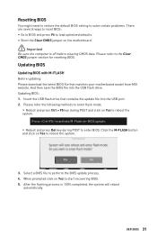
Insert the USB flash drive that matches your motherboard model from MSI website. Select a BIOS file to start recovering BIOS. 5. Updating BIOS: 1. When prompted click on Yes to the Clear CMOS jumper section for BIOS update. ▪▪Reboot and press Del key during POST and click on the ...mode. ▪▪Reboot and press Ctrl + F5 key during POST to reboot the system. Updating BIOS Updating BIOS with M-FLASH Before updating: Please download the latest BIOS file that contains the update file into the USB flash drive. After the flashing process is off before...
Insert the USB flash drive that matches your motherboard model from MSI website. Select a BIOS file to start recovering BIOS. 5. Updating BIOS: 1. When prompted click on Yes to the Clear CMOS jumper section for BIOS update. ▪▪Reboot and press Del key during POST and click on the ...mode. ▪▪Reboot and press Ctrl + F5 key during POST to reboot the system. Updating BIOS Updating BIOS with M-FLASH Before updating: Please download the latest BIOS file that contains the update file into the USB flash drive. After the flashing process is off before...

User Manual
Page 44
Please download the latest BIOS file that contains the MSI.ROM file into the Flash BIOS Port on the rear I/O panel. 5. Connect the power supply to CPU_PWR1 and ATX_PWR1. (No need to the root of your motherboard model from the MSI® website. 2. Rename the BIOS file to MSI.ROM, and save it to install CPU and memory.) 4. The LED will be turned off when the process is completed. 32 UEFI BIOS Plug the USB flash drive that matches your USB flash drive. 3. Press the Flash BIOS Button to flash BIOS, and the LED starts flashing. 6. Updating BIOS with Flash BIOS Button 1.
Please download the latest BIOS file that contains the MSI.ROM file into the Flash BIOS Port on the rear I/O panel. 5. Connect the power supply to CPU_PWR1 and ATX_PWR1. (No need to the root of your motherboard model from the MSI® website. 2. Rename the BIOS file to MSI.ROM, and save it to install CPU and memory.) 4. The LED will be turned off when the process is completed. 32 UEFI BIOS Plug the USB flash drive that matches your USB flash drive. 3. Press the Flash BIOS Button to flash BIOS, and the LED starts flashing. 6. Updating BIOS with Flash BIOS Button 1.

User Manual
Page 45
...it provides the basic system information and allows you to select the A-XMP profile for performance optimization. This function is only available when both of BIOS setup. This function is only available when the system, memory and CPU are supporting this function. ⚠⚠Important Please don't make any ...; A-XMP Profile - Move the mouse over a blank space and right click the mouse to toggle the CREATOR GENIE for memory to overclock. UEFI BIOS 33 click on it to configure the basic setting. press this tab or the F12 key to take a screenshot and save it to exit the...
...it provides the basic system information and allows you to select the A-XMP profile for performance optimization. This function is only available when both of BIOS setup. This function is only available when the system, memory and CPU are supporting this function. ⚠⚠Important Please don't make any ...; A-XMP Profile - Move the mouse over a blank space and right click the mouse to toggle the CREATOR GENIE for memory to overclock. UEFI BIOS 33 click on it to configure the basic setting. press this tab or the F12 key to take a screenshot and save it to exit the...

User Manual
Page 46
... USB flash drive. ∙∙ Hardware Monitor - click on this button to enter the M-Flash menu that provides the way to update BIOS with the motherboard you to manually control the fan speed by clicking on this button to enter the Hardware Monitor menu that allows you purchased...8729;∙ Favorites - click on these buttons. shows the CPU/ DDR speed, CPU/ MB temperature, MB/ CPU type, memory size, CPU/ DDR voltage, BIOS version and build date. ∙∙ Boot device priority bar - you can move the device icons to show the information of connected component. ∙∙...
... USB flash drive. ∙∙ Hardware Monitor - click on this button to enter the M-Flash menu that provides the way to update BIOS with the motherboard you to manually control the fan speed by clicking on this button to enter the Hardware Monitor menu that allows you purchased...8729;∙ Favorites - click on these buttons. shows the CPU/ DDR speed, CPU/ MB temperature, MB/ CPU type, memory size, CPU/ DDR voltage, BIOS version and build date. ∙∙ Boot device priority bar - you can move the device icons to show the information of connected component. ∙∙...

User Manual
Page 47
Select a BIOS item not only on BIOS menu but also on favorite menu. 2. UEFI BIOS 35 Right-click or press F2 key. 3. Select a BIOS item on search page. 2. Choose Delete and click on OK. ▪▪To delete a BIOS item from favorite menu 1. Choose a favorite page and click on OK. ▪▪To add a BIOS item to a favorite menu 1. Right-click or press F2 key. 3.
Select a BIOS item not only on BIOS menu but also on favorite menu. 2. UEFI BIOS 35 Right-click or press F2 key. 3. Select a BIOS item on search page. 2. Choose Delete and click on OK. ▪▪To delete a BIOS item from favorite menu 1. Choose a favorite page and click on OK. ▪▪To add a BIOS item to a favorite menu 1. Right-click or press F2 key. 3.

User Manual
Page 48
.... ∙∙ Menu display - provides the way to be configured. 36 UEFI BIOS BIOS menu selection BIOS menu selection Menu display ∙∙ BIOS menu selection - Increasing the frequency may get better performance. ▪▪M-FLASH - provides BIOS setting items and information to update BIOS with a USB flash drive. ▪▪OC PROFILE - the following options...
.... ∙∙ Menu display - provides the way to be configured. 36 UEFI BIOS BIOS menu selection BIOS menu selection Menu display ∙∙ BIOS menu selection - Increasing the frequency may get better performance. ▪▪M-FLASH - provides BIOS setting items and information to update BIOS with a USB flash drive. ▪▪OC PROFILE - the following options...
User Manual
Page 49
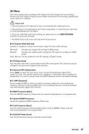
..., we advise you to use * as the symbol for the OC settings of OC settings. [Normal] Provides the regular OC settings in BIOS setup. [Expert] Provides the advanced OC settings for OC expert to determine CPU clock speed. Read-only. ▶▶FCLK Frequency [Auto...] Sets the FCLK frequency (Internal Data Fabric clock of memory module for easy overclocking. ∙∙The BIOS items in BIOS setup. UEFI BIOS 37 Please note the overclocking behavior is not guaranteed. ▶▶Adjusted DRAM Frequency Shows the adjusted DRAM frequency. Please note...
..., we advise you to use * as the symbol for the OC settings of OC settings. [Normal] Provides the regular OC settings in BIOS setup. [Expert] Provides the advanced OC settings for OC expert to determine CPU clock speed. Read-only. ▶▶FCLK Frequency [Auto...] Sets the FCLK frequency (Internal Data Fabric clock of memory module for easy overclocking. ∙∙The BIOS items in BIOS setup. UEFI BIOS 37 Please note the overclocking behavior is not guaranteed. ▶▶Adjusted DRAM Frequency Shows the adjusted DRAM frequency. Please note...


