User Manual
Page 14
JCOM1: Serial Port Connector 33 JLED1: RGB LED strip connector 34 JBAT1: Clear CMOS (Reset BIOS) Jumper 35 EZ Debug LEDs ...35 GPU LED ...35 BIOS Setup ...36 Entering BIOS Setup 36 Resetting BIOS...37 Updating BIOS...37 EZ Mode ...38 Advanced Mode ...40 SETTINGS...41 Advanced...41 Boot...46 Security ...47 Save & Exit...48 OC...® 7 64-bit/ Windows®10 64-bit 55 Installing Drivers 55 Installing Utilities 55 LIVE UPDATE 6...56 COMMAND CENTER 58 RAMDISK...62 X-BOOST ...63 MSI SMART TOOL 65 MYSTIC LIGHT...67 CPU-Z...68 Troubleshooting 69 Regulatory Notices 70 14 Contents
JCOM1: Serial Port Connector 33 JLED1: RGB LED strip connector 34 JBAT1: Clear CMOS (Reset BIOS) Jumper 35 EZ Debug LEDs ...35 GPU LED ...35 BIOS Setup ...36 Entering BIOS Setup 36 Resetting BIOS...37 Updating BIOS...37 EZ Mode ...38 Advanced Mode ...40 SETTINGS...41 Advanced...41 Boot...46 Security ...47 Save & Exit...48 OC...® 7 64-bit/ Windows®10 64-bit 55 Installing Drivers 55 Installing Utilities 55 LIVE UPDATE 6...56 COMMAND CENTER 58 RAMDISK...62 X-BOOST ...63 MSI SMART TOOL 65 MYSTIC LIGHT...67 CPU-Z...68 Troubleshooting 69 Regulatory Notices 70 14 Contents

User Manual
Page 17
... control y ATX Form Factor y 12 in . (30.4 cm x 24.3 cm) y 1x 128 Mb flash y UEFI AMI BIOS y Multi-language y Drivers y SUPER CHARGER y COMMAND CENTER y LIVE UPDATE 6 y MSI SMART TOOL y MYSTIC LIGHT y X-BOOST y RAMDISK y NETWORK GENIE y CPU-Z MSI GAMING y Google Chrome™ ,Google Toolbar, Google Drive y Norton™ Internet Security Solution y Audio Boost y Turbo...
... control y ATX Form Factor y 12 in . (30.4 cm x 24.3 cm) y 1x 128 Mb flash y UEFI AMI BIOS y Multi-language y Drivers y SUPER CHARGER y COMMAND CENTER y LIVE UPDATE 6 y MSI SMART TOOL y MYSTIC LIGHT y X-BOOST y RAMDISK y NETWORK GENIE y CPU-Z MSI GAMING y Google Chrome™ ,Google Toolbar, Google Drive y Norton™ Internet Security Solution y Audio Boost y Turbo...

User Manual
Page 23
... JLED1 JLPT1 JTPM1 JUSB1~2 JUSB3~4 M2_1 PCI_E1~4, PCI1~2 SATA1~4 Port Type Fan Connectors Power Connectors AM4 Socket DIMM Slots Front Audio Connector Clear CMOS (Reset BIOS) Jumper Chassis Intrusion Connector Serial Port Connector Front Panel Connectors RGB LED strip connector Parallel Port Connector TPM Module Connector USB 2.0 Connectors USB 3.1 Gen1 Connectors...
... JLED1 JLPT1 JTPM1 JUSB1~2 JUSB3~4 M2_1 PCI_E1~4, PCI1~2 SATA1~4 Port Type Fan Connectors Power Connectors AM4 Socket DIMM Slots Front Audio Connector Clear CMOS (Reset BIOS) Jumper Chassis Intrusion Connector Serial Port Connector Front Panel Connectors RGB LED strip connector Parallel Port Connector TPM Module Connector USB 2.0 Connectors USB 3.1 Gen1 Connectors...

User Manual
Page 24
...removing the CPU. The yellow triangle is not recommended. y When installing a CPU, always remember to the AM4 processor's architecture. MSI® does not guarantee the damages or risks caused by inadequate operation beyond product specifications is the Pin 1 indicator. CPU Socket ...CPU from the power outlet before booting your system. Important y When changing the processor, the system configuration could be cleared and reset BIOS to default values, due to install a CPU heatsink. y This motherboard is necessary to support overclocking. A CPU heatsink is designed...
...removing the CPU. The yellow triangle is not recommended. y When installing a CPU, always remember to the AM4 processor's architecture. MSI® does not guarantee the damages or risks caused by inadequate operation beyond product specifications is the Pin 1 indicator. CPU Socket ...CPU from the power outlet before booting your system. Important y When changing the processor, the system configuration could be cleared and reset BIOS to default values, due to install a CPU heatsink. y This motherboard is necessary to support overclocking. A CPU heatsink is designed...

User Manual
Page 25
y Due to operate the memory at the marked or at a lower frequency than the marked value when overclocking due to BIOS and find the DRAM Frequency! y The stability and compatibility of installed. to set the memory frequency if you want to AM4 CPU/memory controller... official specification limitation, the frequency of memory modules may operate at a higher frequency. Please refer www.msi.com for full DIMMs installation or overclocking. Overview of memory will be a little less than the marked value under the default state. Go to ...
y Due to operate the memory at the marked or at a lower frequency than the marked value when overclocking due to BIOS and find the DRAM Frequency! y The stability and compatibility of installed. to set the memory frequency if you want to AM4 CPU/memory controller... official specification limitation, the frequency of memory modules may operate at a higher frequency. Please refer www.msi.com for full DIMMs installation or overclocking. Overview of memory will be a little less than the marked value under the default state. Go to ...

User Manual
Page 31
... connectors can be classified as PWM (Pulse Width Modulation) Mode or DC Mode. When you to adjust fan speed in relation to a fan connector in BIOS > HARDWARE MONITOR. PWM Mode fan connectors provide constant 12V output and adjust fan speed with speed control signal.
... connectors can be classified as PWM (Pulse Width Modulation) Mode or DC Mode. When you to adjust fan speed in relation to a fan connector in BIOS > HARDWARE MONITOR. PWM Mode fan connectors provide constant 12V output and adjust fan speed with speed control signal.

User Manual
Page 32
...) Trigger the chassis intrusion event Using chassis intrusion detector 1. Press F10 to save and exit and then press the Enter key to BIOS > SETTINGS > Security > Chassis Intrusion Configuration. 2. JLPT1: Parallel Port Connector This connector allows you to Enabled. 5. Close the ... Resetting the chassis intrusion warning 1. JCI1: Chassis Intrusion Connector This connector allows you to select Yes. Connect the JCI1 connector to BIOS > SETTINGS > Security > Chassis Intrusion Configuration. 4. Go to the chassis intrusion switch/ sensor on . Press F10 to save and...
...) Trigger the chassis intrusion event Using chassis intrusion detector 1. Press F10 to save and exit and then press the Enter key to BIOS > SETTINGS > Security > Chassis Intrusion Configuration. 2. JLPT1: Parallel Port Connector This connector allows you to Enabled. 5. Close the ... Resetting the chassis intrusion warning 1. JCI1: Chassis Intrusion Connector This connector allows you to select Yes. Connect the JCI1 connector to BIOS > SETTINGS > Security > Chassis Intrusion Configuration. 4. Go to the chassis intrusion switch/ sensor on . Press F10 to save and...

User Manual
Page 35
... corresponding LED stays lit until the problem is not detected or fail. DRAM - BOOT - indicates DRAM is solved. Keep Data (default) Clear CMOS/ Reset BIOS Resetting BIOS to short JBAT1 for about 5-10 seconds. 3. indicates CPU is not detected or fail. Power off the computer but DO NOT unplug the power cord...
... corresponding LED stays lit until the problem is not detected or fail. DRAM - BOOT - indicates DRAM is solved. Keep Data (default) Clear CMOS/ Reset BIOS Resetting BIOS to short JBAT1 for about 5-10 seconds. 3. indicates CPU is not detected or fail. Power off the computer but DO NOT unplug the power cord...

User Manual
Page 36
...: Save Overclocking Profile F10: Save Change and Reset* F12: Take a screenshot and save it provides the modification information. y The BIOS items will vary with BIOS. Important y BIOS items are for better system performance. y The pictures in normal conditions. Function key F1: General Help list F2: Add/ Remove ... defaults F7: Switch between Yes or No to enter Boot Menu message appears on the screen during the boot process. BIOS Setup The default settings offer the optimal performance for system stability in this chapter are continuously update for reference only and may be...
...: Save Overclocking Profile F10: Save Change and Reset* F12: Take a screenshot and save it provides the modification information. y The BIOS items will vary with BIOS. Important y BIOS items are for better system performance. y The pictures in normal conditions. Function key F1: General Help list F2: Add/ Remove ... defaults F7: Switch between Yes or No to enter Boot Menu message appears on the screen during the boot process. BIOS Setup The default settings offer the optimal performance for system stability in this chapter are continuously update for reference only and may be...
User Manual
Page 37
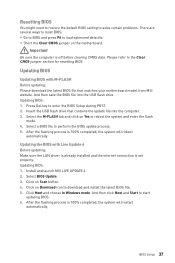
... POST. 2. Click on Download icon to download and install the latest BIOS file. 5. BIOS Setup 37 Press Del key to the Clear CMOS jumper section for resetting BIOS. Select a BIOS file to start updating BIOS. 6. Install and launch MSI LIVE UPDATE 6. 2. And then save the BIOS file into the computer. 3. After the flashing process is off before...
... POST. 2. Click on Download icon to download and install the latest BIOS file. 5. BIOS Setup 37 Press Del key to the Clear CMOS jumper section for resetting BIOS. Select a BIOS file to start updating BIOS. 6. Install and launch MSI LIVE UPDATE 6. 2. And then save the BIOS file into the computer. 3. After the flashing process is off before...
User Manual
Page 38
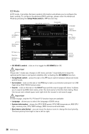
... Boot device priority bar Information display M-Flash Favorites Hardware Monitor Function buttons y OC GENIE 4 switch - It allows you to select the language of BIOS setup. y System information - EZ Mode At EZ mode, it provides the basic system information and allows you can move the device icons to change... the boot priority. allows you to right. 38 BIOS Setup y Boot device priority bar - Important Please don't make any changes in OC menu and don't load defaults to toggle the OC GENIE...
... Boot device priority bar Information display M-Flash Favorites Hardware Monitor Function buttons y OC GENIE 4 switch - It allows you to select the language of BIOS setup. y System information - EZ Mode At EZ mode, it provides the basic system information and allows you can move the device icons to change... the boot priority. allows you to right. 38 BIOS Setup y Boot device priority bar - Important Please don't make any changes in OC menu and don't load defaults to toggle the OC GENIE...
User Manual
Page 39
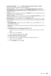
... on OK. ƒ To delete a BIOS item from favorite page 1. press the F3 key to select a BIOS menu (e.g. allows you to add the frequently-used BIOS setting items. ƒ Default HomePage - Move the mouse over a BIOS item not only on BIOS menu but also on left side to ... drive. allows you can save and access favorite/ frequently-used / favorite BIOS setting items in one page. ƒ To add a BIOS item to display related information. BIOS Setup 39 y Hardware Monitor - Move the mouse over a BIOS item on OK. enable or disable the LAN Option ROM, HD audio controller...
... on OK. ƒ To delete a BIOS item from favorite page 1. press the F3 key to select a BIOS menu (e.g. allows you to add the frequently-used BIOS setting items. ƒ Default HomePage - Move the mouse over a BIOS item not only on BIOS menu but also on left side to ... drive. allows you can save and access favorite/ frequently-used / favorite BIOS setting items in one page. ƒ To add a BIOS item to display related information. BIOS Setup 39 y Hardware Monitor - Move the mouse over a BIOS item on OK. enable or disable the LAN Option ROM, HD audio controller...
User Manual
Page 40
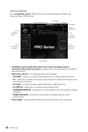
... Advanced Mode Press Setup Mode switch or F7 function key can switch between EZ Mode and Advanced Mode in BIOS setup. y BIOS menu selection - allows you to manage overclocking profiles. ƒ HARDWARE MONITOR - allows you to specify the ...following options are available: ƒ SETTINGS - OC GENIE 4 switch Setup Mode switch Screenshot Search Language System information Boot device priority bar BIOS menu selection BIOS menu selection Menu display y OC GENIE 4 switch/ Setup Mode switch/ Screenshot/ Language/ System information/ Boot device priority bar - provides...
... Advanced Mode Press Setup Mode switch or F7 function key can switch between EZ Mode and Advanced Mode in BIOS setup. y BIOS menu selection - allows you to manage overclocking profiles. ƒ HARDWARE MONITOR - allows you to specify the ...following options are available: ƒ SETTINGS - OC GENIE 4 switch Setup Mode switch Screenshot Search Language System information Boot device priority bar BIOS menu selection BIOS menu selection Menu display y OC GENIE 4 switch/ Setup Mode switch/ Screenshot/ Language/ System information/ Boot device priority bar - provides...

User Manual
Page 41
... and power cable connections of the device and motherboard. The month from 1 to switch between time elements. The year can be adjusted by BIOS. f SATA PortX Shows the information of the week, from Sun to enter the sub-menu. Advanced f PCI Subsystem Settings Sets PCI,...SATA device is . Press Enter to Sat, determined by users. f System Information Shows detailed system information, including CPU type, BIOS version, and Memory (read only). BIOS Setup 41 Use tab key to 31 can be keyed by numeric function keys. through Dec. The time format is . Read...
... and power cable connections of the device and motherboard. The month from 1 to switch between time elements. The year can be adjusted by BIOS. f SATA PortX Shows the information of the week, from Sun to enter the sub-menu. Advanced f PCI Subsystem Settings Sets PCI,...SATA device is . Press Enter to Sat, determined by users. f System Information Shows detailed system information, including CPU type, BIOS version, and Memory (read only). BIOS Setup 41 Use tab key to 31 can be keyed by numeric function keys. through Dec. The time format is . Read...
User Manual
Page 42
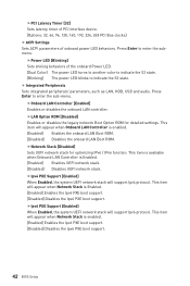
.... This item is available when Onboard LAN Controller is enabled. [Enabled] Enables the Ipv6 PXE boot support. [Disabled] Disables the Ipv6 PXE boot support. 42 BIOS Setup Press Enter to enter the submenu. This item will appear when Network Stack is Enabled. [Enabled] Enables UEFI network stack. [Disabled] Disables UEFI network...
.... This item is available when Onboard LAN Controller is enabled. [Enabled] Enables the Ipv6 PXE boot support. [Disabled] Disables the Ipv6 PXE boot support. 42 BIOS Setup Press Enter to enter the submenu. This item will appear when Network Stack is Enabled. [Enabled] Enables UEFI network stack. [Disabled] Disables UEFI network...
User Manual
Page 43
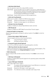
... [Auto] (optional) Selects a fixed amount of the onboard SATA controller. [AHCI Mode] Specify the AHCI mode for SATA storage devices. BIOS Setup 43 fHPET [Enabled] Enables or disables the HPET (High Precision Event Timers) support. This item will be available when Integrated Graphics is... for the operating system without XHCI hand-off support for SATA storage devices. fIntegrated Graphics [Auto] (optional) If set to Force, BIOS will be unavailable under legacy mode. [Disabled] The USB devices will enable the integrated graphics controller. fXHCI Hand-off [Enabled] Enables or...
... [Auto] (optional) Selects a fixed amount of the onboard SATA controller. [AHCI Mode] Specify the AHCI mode for SATA storage devices. BIOS Setup 43 fHPET [Enabled] Enables or disables the HPET (High Precision Event Timers) support. This item will be available when Integrated Graphics is... for the operating system without XHCI hand-off support for SATA storage devices. fIntegrated Graphics [Auto] (optional) If set to Force, BIOS will be unavailable under legacy mode. [Disabled] The USB devices will enable the integrated graphics controller. fXHCI Hand-off [Enabled] Enables or...
User Manual
Page 44
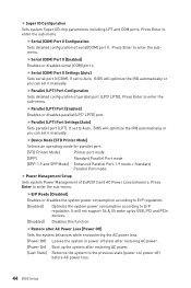
...Port mode. fErP Ready [Disabled] Enables or disables the system power consumption according to ErP regulation. [Enabled] Optimize the system power consumption according to Auto, BIOS will not support S4 & S5 wake up the system after restoring AC power. [Last State] Restores the system to Auto... optimize the IRQ automatically or you can set to the previous state (power on/ power off) before AC power loss. 44 BIOS Setup fSerial (COM) Port 0 Configuration Sets detailed configuration of serial(COM) port 0. If set it manually. It will optimize the IRQ automatically or ...
...Port mode. fErP Ready [Disabled] Enables or disables the system power consumption according to ErP regulation. [Enabled] Optimize the system power consumption according to Auto, BIOS will not support S4 & S5 wake up the system after restoring AC power. [Last State] Restores the system to Auto... optimize the IRQ automatically or you can set to the previous state (power on/ power off) before AC power loss. 44 BIOS Setup fSerial (COM) Port 0 Configuration Sets detailed configuration of serial(COM) port 0. If set it manually. It will optimize the IRQ automatically or ...
User Manual
Page 45
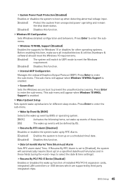
...] Enables the system to boot up on a specified date/hour/minute/second in these fields (using the + and - BIOS Setup 45 fInternal GOP Configuration Manages the onboard Graphics Output Protocol (GOP). Press Enter to enter the sub-menu. keys to prevent the unauthorized ...the wake up events will switch to UEFI mode to meet the Windows 10 requirements. [Enabled] The system will be defined by BIOS or operating system. [BIOS] Activates the following items, set to [Enabled], the system will automatically resume (boot up behaviors for other operating systems. Before ...
...] Enables the system to boot up on a specified date/hour/minute/second in these fields (using the + and - BIOS Setup 45 fInternal GOP Configuration Manages the onboard Graphics Output Protocol (GOP). Press Enter to enter the sub-menu. keys to prevent the unauthorized ...the wake up events will switch to UEFI mode to meet the Windows 10 requirements. [Enabled] The system will be defined by BIOS or operating system. [BIOS] Activates the following items, set to [Enabled], the system will automatically resume (boot up behaviors for other operating systems. Before ...
User Manual
Page 46
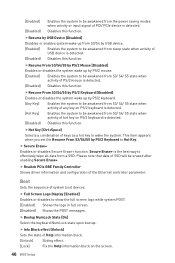
.../2 keyboard is detected. [Hot Key] Enables the system to be awakened from S3/ S4/ S5 state when activity of hot key on the screen. 46 BIOS Setup fResume From S3/S4/S5 by PS/2 Keyboard [Disabled] Enables or disables the system wake up by PS/2 Keyboard to show the full screen...
.../2 keyboard is detected. [Hot Key] Enables the system to be awakened from S3/ S4/ S5 state when activity of hot key on the screen. 46 BIOS Setup fResume From S3/S4/S5 by PS/2 Keyboard [Disabled] Enables or disables the system wake up by PS/2 Keyboard to show the full screen...
User Manual
Page 47
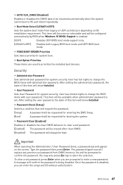
... is set. This item will become un-selectable and will confirm the password is disabled, you are used to change the BIOS items with administrator password. f Boot Option Priorities These items are prompted to confirm the password. Once the password is being ...the selection. f Password Check [Setup] Selects a condition that will request the password. [Setup] A password will be requested for entering the BIOS Setup. [Boot] A password will appear on OS installation requirement. Important When selecting the Administrator / User Password items, a password box will be...
... is set. This item will become un-selectable and will confirm the password is disabled, you are used to change the BIOS items with administrator password. f Boot Option Priorities These items are prompted to confirm the password. Once the password is being ...the selection. f Password Check [Setup] Selects a condition that will request the password. [Setup] A password will be requested for entering the BIOS Setup. [Boot] A password will appear on OS installation requirement. Important When selecting the Administrator / User Password items, a password box will be...


