

User Guide
Page 2
... we reserve the right to the correctness of its contents. Alternatively, please try the following help resources for FAQ, technical guide, BIOS updates, driver updates, and other countries. Our products are registered trademarks of AMD Corporation. W indows® 95/98/2000/NT... and nForce are registered trademarks of International Business Machines Corporation. AMI® is a registered trademark of Phoenix Technologies Ltd. Visit the MSI website for further guidance. PS/2 and OS®/2 are registered trademarks or trademarks of NVIDIA Corporation in the United States and/or...
... we reserve the right to the correctness of its contents. Alternatively, please try the following help resources for FAQ, technical guide, BIOS updates, driver updates, and other countries. Our products are registered trademarks of AMD Corporation. W indows® 95/98/2000/NT... and nForce are registered trademarks of International Business Machines Corporation. AMI® is a registered trademark of Phoenix Technologies Ltd. Visit the MSI website for further guidance. PS/2 and OS®/2 are registered trademarks or trademarks of NVIDIA Corporation in the United States and/or...
User Guide
Page 8
...Memory ...2-7 Power Supply ...2-8 Back Panel ...2-9 Connectors ...2-11 Jumpers ...2-18 Slots ...2-19 Chapter 3 BIOS Setup 3-1 Entering Setup ...3-2 The Main Menu ...3-4 Standard CMOS Features 3-6 Advanced BIOS Features 3-9 Integrated Peripherals 3-11 Power Management Setup 3-13 PNP/PCI Configurations 3-15 H/W Monitor ...3-17... Cell Menu ...3-18 Load Fail-Safe/ Optimized Defaults 3-21 BIOS Setting Password 3-22 Appendix A Dual Core Center A-1 Activating Dual Core Center A-2 Main ...A-3 DOT (Dynamic OverClocking A-5 ...
...Memory ...2-7 Power Supply ...2-8 Back Panel ...2-9 Connectors ...2-11 Jumpers ...2-18 Slots ...2-19 Chapter 3 BIOS Setup 3-1 Entering Setup ...3-2 The Main Menu ...3-4 Standard CMOS Features 3-6 Advanced BIOS Features 3-9 Integrated Peripherals 3-11 Power Management Setup 3-13 PNP/PCI Configurations 3-15 H/W Monitor ...3-17... Cell Menu ...3-18 Load Fail-Safe/ Optimized Defaults 3-21 BIOS Setting Password 3-22 Appendix A Dual Core Center A-1 Activating Dual Core Center A-2 Main ...A-3 DOT (Dynamic OverClocking A-5 ...

User Guide
Page 9
FAN Speed ...A-8 Temperature ...A-9 User Profile ...A-10 Appendix B Intel ICH7R SATA RAID B-1 ICH7R Introduction B-2 BIOS Configuration B-3 Installing Software B-9 RAID Migration Instructions B-15 Degraded RAID Array B-22 ix
FAN Speed ...A-8 Temperature ...A-9 User Profile ...A-10 Appendix B Intel ICH7R SATA RAID B-1 ICH7R Introduction B-2 BIOS Configuration B-3 Installing Software B-9 RAID Migration Instructions B-15 Degraded RAID Array B-22 ix
User Guide
Page 20
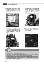
.... MS-7507 Mainboard 9. Press down the load lever lightly onto the load plate, and then secure the lever with the plastic cap covered (shown in BIOS (Chapter 3). 2. Press the four hooks down the cooler until its four clips get wedged into the holes of your CPU socket pin with the hook...
.... MS-7507 Mainboard 9. Press down the load lever lightly onto the load plate, and then secure the lever with the plastic cap covered (shown in BIOS (Chapter 3). 2. Press the four hooks down the cooler until its four clips get wedged into the holes of your CPU socket pin with the hook...
User Guide
Page 28
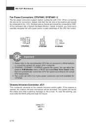
... record this status and show a warning message on -board, you must use a specially designed fan with +12V. To clear the warning, you must enter the BIOS utility and clear the record. GND +1 2V SE NS OR CONTROL SE NS OR +1 2V GND CPUFAN1 SYSFAN1 GND +1 2V SE NS OR SYSFAN2 Important... CPU temperature. 3. MS-7507 Mainboard Fan Power Connectors: CPUFAN1, SYSFAN1~2 The fan power connectors support system cooling fan with speed sensor to take advantage of BIOS and install Dual Core Center utility that the red wire is opened, the chassis intrusion mechanism will be activated.
... record this status and show a warning message on -board, you must use a specially designed fan with +12V. To clear the warning, you must enter the BIOS utility and clear the record. GND +1 2V SE NS OR CONTROL SE NS OR +1 2V GND CPUFAN1 SYSFAN1 GND +1 2V SE NS OR SYSFAN2 Important... CPU temperature. 3. MS-7507 Mainboard Fan Power Connectors: CPUFAN1, SYSFAN1~2 The fan power connectors support system cooling fan with speed sensor to take advantage of BIOS and install Dual Core Center utility that the red wire is opened, the chassis intrusion mechanism will be activated.
User Guide
Page 34
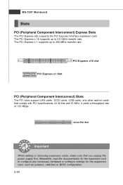
.... Meanwhile, read the documentation for the expansion card to configure any necessary hardware or software settings for the expansion card, such as jumpers, switches or BIOS configuration. 2-20
.... Meanwhile, read the documentation for the expansion card to configure any necessary hardware or software settings for the expansion card, such as jumpers, switches or BIOS configuration. 2-20

User Guide
Page 36
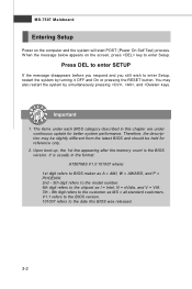
Chapter 3 BIOS Setup BIOS Setup This chapter provides information on the screen during the system booting up, and requests you to run the Setup program when: ² An error message appears on the BIOS Setup program and allows you to change the default settings for optimum use. You may need to run SETUP. ² You want to configure the system for customized features. 3-1
Chapter 3 BIOS Setup BIOS Setup This chapter provides information on the screen during the system booting up, and requests you to run the Setup program when: ² An error message appears on the BIOS Setup program and allows you to change the default settings for optimum use. You may need to run SETUP. ² You want to configure the system for customized features. 3-1
User Guide
Page 37
... digit refers to the customer as MS = all standard customers. Upon boot-up, the 1st line appearing after the memory count is usually in this BIOS was released. 3-2 MS-7507 Mainboard Entering Setup Power on the screen, press key to enter Setup. Press DEL to enter SETUP If the message disappears... pressing , , and keys. Therefore, the description may also restart the system by turning it OFF and On or pressing the RESET button. It is the BIOS version. W hen the message below appears on the computer and the system will start POST (Power On Self Test) process.
... digit refers to the customer as MS = all standard customers. Upon boot-up, the 1st line appearing after the memory count is usually in this BIOS was released. 3-2 MS-7507 Mainboard Entering Setup Power on the screen, press key to enter Setup. Press DEL to enter SETUP If the message disappears... pressing , , and keys. Therefore, the description may also restart the system by turning it OFF and On or pressing the RESET button. It is the BIOS version. W hen the message below appears on the computer and the system will start POST (Power On Self Test) process.

User Guide
Page 38
BIOS Setup Control Keys Enter> Move to the previous item Move to the next item Move to the item in the right hand Select the item ... menu, just press the . Main Menu The main menu lists the setup functions you can call up this screen from this field. General Help The BIOS setup program provides a General Help screen. The on-line description of the highlighted setup function is the Main Menu. The Help screen lists the appropriate...
BIOS Setup Control Keys Enter> Move to the previous item Move to the next item Move to the item in the right hand Select the item ... menu, just press the . Main Menu The main menu lists the setup functions you can call up this screen from this field. General Help The BIOS setup program provides a General Help screen. The on-line description of the highlighted setup function is the Main Menu. The Help screen lists the appropriate...
User Guide
Page 39
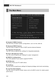
... overclocking. H/W Monitor This entry shows your system supports PnP/PCI. Load Fail-Safe Defaults Use this menu to load the default values set by the BIOS vendor for power management. Power Management Setup Use this menu to specify your settings for basic system configurations, such as time, date etc. Integrated Peripherals... health status. MS-7507 Mainboard The Main Menu Standard CMOS Features Use this menu to setup the items of AMI® special enhanced features. Advanced BIOS Features Use this menu for integrated peripherals.
... overclocking. H/W Monitor This entry shows your system supports PnP/PCI. Load Fail-Safe Defaults Use this menu to load the default values set by the BIOS vendor for power management. Power Management Setup Use this menu to specify your settings for basic system configurations, such as time, date etc. Integrated Peripherals... health status. MS-7507 Mainboard The Main Menu Standard CMOS Features Use this menu to setup the items of AMI® special enhanced features. Advanced BIOS Features Use this menu for integrated peripherals.

User Guide
Page 40
BIOS Setup Load Optimized Defaults Use this menu to set by the mainboard manufacturer specifically for BIOS. Save & Exit Setup Save changes to load the default values set the password for optimal performance of the mainboard. BIOS Setting Password Use this menu to CMOS and exit setup. Exit Without Saving Abandon all changes and exit setup. 3-5
BIOS Setup Load Optimized Defaults Use this menu to set by the mainboard manufacturer specifically for BIOS. Save & Exit Setup Save changes to load the default values set the password for optimal performance of the mainboard. BIOS Setting Password Use this menu to CMOS and exit setup. Exit Without Saving Abandon all changes and exit setup. 3-5
User Guide
Page 41
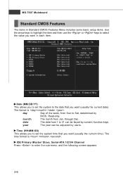
month The month from 1 to 31 can be keyed by numeric function keys. year The year can be adjusted by BIOS. IDE Primary Master/ Slave, Serial-ATA 1/2/3/4 Channel Press to select the value you want (usually the current date). day Day of the week, from Sun ...
month The month from 1 to 31 can be keyed by numeric function keys. year The year can be adjusted by BIOS. IDE Primary Master/ Slave, Serial-ATA 1/2/3/4 Channel Press to select the value you want (usually the current date). day Day of the week, from Sun ...
User Guide
Page 42
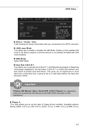
... hard disk failure. Setting to enable or disable the LBA Mode. DM A M ode Select DMA Mode. Floppy A This item allows you to the SATA connector. BIOS Setup Device / Vender / Size It will showing the device information that you connected to set the type of floppy drives installed. This allows you connect...
... hard disk failure. Setting to enable or disable the LBA Mode. DM A M ode Select DMA Mode. Floppy A This item allows you to the SATA connector. BIOS Setup Device / Vender / Size It will showing the device information that you connected to set the type of floppy drives installed. This allows you connect...
User Guide
Page 43
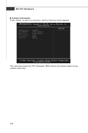
MS-7507 Mainboard System Information Press to enter the sub-menu, and the following screen appears. This sub-menu shows the CPU information, BIOS version and memory status of your system (read only). 3-8
MS-7507 Mainboard System Information Press to enter the sub-menu, and the following screen appears. This sub-menu shows the CPU information, BIOS version and memory status of your system (read only). 3-8

User Guide
Page 44
... on . Setting to [Off] will expand available IRQ resources for the system. 3-9 IOAPIC Function This field is able to run in APIC mode. Advanced BIOS Features BIOS Setup Full Screen LOGO Display This item enables you to show the company logo on the full screen at boot. [Disabled] Shows the POST messages...
... on . Setting to [Off] will expand available IRQ resources for the system. 3-9 IOAPIC Function This field is able to run in APIC mode. Advanced BIOS Features BIOS Setup Full Screen LOGO Display This item enables you to show the company logo on the full screen at boot. [Disabled] Shows the POST messages...
User Guide
Page 45
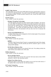
... from the 1st/ 2nd boot device. MS-7507 Mainboard MPS Table Version This field allows you to set the first/ second/ third boot device where BIOS attempts to load the disk operating system. The processor uses Hyper-Threading technology to execute the instructions. In this way, the system performance is part...
... from the 1st/ 2nd boot device. MS-7507 Mainboard MPS Table Version This field allows you to set the first/ second/ third boot device where BIOS attempts to load the disk operating system. The processor uses Hyper-Threading technology to execute the instructions. In this way, the system performance is part...
User Guide
Page 46
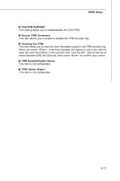
... to confirm your choice. TPM Owner Status This item is not configurable. Excute TPM Command This item allows you to enable/disable the TCG/TPM. BIOS Setup TCG/TPM SUPPORT This setting allows you to enable or disable the TPM security chip.
... to confirm your choice. TPM Owner Status This item is not configurable. Excute TPM Command This item allows you to enable/disable the TCG/TPM. BIOS Setup TCG/TPM SUPPORT This setting allows you to enable or disable the TPM security chip.
User Guide
Page 47
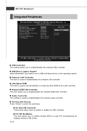
... This item is used to enable/disable the onboard LAN controller. MS-7507 Mainboard Integrated Peripherals USB Controller This setting allows you to enable/ disable BIOS to used to decide whether to invoke the Boot ROM of the LAN controller.
... This item is used to enable/disable the onboard LAN controller. MS-7507 Mainboard Integrated Peripherals USB Controller This setting allows you to enable/ disable BIOS to used to decide whether to invoke the Boot ROM of the LAN controller.
User Guide
Page 48
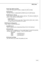
... disable the SATA controller. Parallel Port There is used to enter the sub-menu: COM Port 1/2 Select an address and corresponding interrupt for SATA devices. BIOS Setup On-Chip SATA Controller These items allow users to select the type of IDE devices. AHCI Devices Group Press to the system. These submenu...
... disable the SATA controller. Parallel Port There is used to enter the sub-menu: COM Port 1/2 Select an address and corresponding interrupt for SATA devices. BIOS Setup On-Chip SATA Controller These items allow users to select the type of IDE devices. AHCI Devices Group Press to the system. These submenu...
User Guide
Page 49
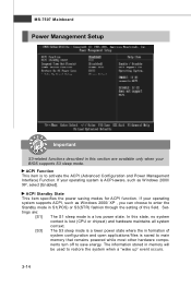
...-7507 Mainboard Power Management Setup Important S3-related functions described in this section are : [S1] The S1 sleep mode is a low power state. If your BIOS supports S3 sleep mode. In this field. ACPI Standby State This item specifies the power saving modes for ACPI function. ACPI Function This item is...
...-7507 Mainboard Power Management Setup Important S3-related functions described in this section are : [S1] The S1 sleep mode is a low power state. If your BIOS supports S3 sleep mode. In this field. ACPI Standby State This item specifies the power saving modes for ACPI function. ACPI Function This item is...


