HDS Gen2 Touch FAQ
Page 1
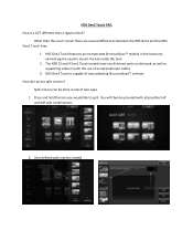
... is capable of auto adjusting StructureScan™ contrast How do I access split screens? The HDS 12 and 9 Gen2 Touch models have two Ethernet ports on the back, as well as supporting video in (with all possible half and half split ... would like to mount the box inside the boat. 2. You will then be created HDS Gen2 Touch features an incorporated StructureScan™ module in one of an optional input cable) 3. HDS Gen2 Touch is a G2T different than the touch screen there are several differences between the HDS Gen2 and the HDS Gen2 Touch lines. 1. Other than a regular...
... is capable of auto adjusting StructureScan™ contrast How do I access split screens? The HDS 12 and 9 Gen2 Touch models have two Ethernet ports on the back, as well as supporting video in (with all possible half and half split ... would like to mount the box inside the boat. 2. You will then be created HDS Gen2 Touch features an incorporated StructureScan™ module in one of an optional input cable) 3. HDS Gen2 Touch is a G2T different than the touch screen there are several differences between the HDS Gen2 and the HDS Gen2 Touch lines. 1. Other than a regular...
Installation Manual
Page 4
... user is encouraged to try to correct the interference by the party responsible for a Class B digital device, pursuant to operate the equipment. Compliance Statements Lowrance HDS-7, HDS-9, and HDS-12 Gen2 Touch: • meet the technical standards in accordance with Part 15.103 of the FCC rules • comply with CE under RTTE directive 1999/5/EC •...
... user is encouraged to try to correct the interference by the party responsible for a Class B digital device, pursuant to operate the equipment. Compliance Statements Lowrance HDS-7, HDS-9, and HDS-12 Gen2 Touch: • meet the technical standards in accordance with Part 15.103 of the FCC rules • comply with CE under RTTE directive 1999/5/EC •...
Installation Manual
Page 5
... Navico. | 3 About this manual This manual is being used under license. • 'HDS', 'StructureScan', 'Navico', 'Lowrance', 'SonicHub', 'SimNet' and 'Skimmer' are trademarks of Navico, registered in the US and other countries and is a reference guide for installing the Lowrance HDS-7, HDS-9, and HDS-12 Gen2 Touch system. Warning: Used when it is emphasized as radars, echo sounders and AIS...
... Navico. | 3 About this manual This manual is being used under license. • 'HDS', 'StructureScan', 'Navico', 'Lowrance', 'SonicHub', 'SimNet' and 'Skimmer' are trademarks of Navico, registered in the US and other countries and is a reference guide for installing the Lowrance HDS-7, HDS-9, and HDS-12 Gen2 Touch system. Warning: Used when it is emphasized as radars, echo sounders and AIS...

Installation Manual
Page 6
Contents 6 HDS Gen2 Touch overview 7 Front - connectors 9 SD card slot 10 Check the contents 11 Display Installation 11 Mounting location 12 Bracket mounting 13 Flush mounting 14 Research 14 Select a transducer location 15 Attaching the transducer 16 Adjusting the transducer 17 Wiring 17 ...2000 device connection 24 NMEA 0183 device connection 25 Video In 25 Connecting video sources 26 Software setup 26 Sonar installation settings 28 Touch Screen Calibration 28 Software upgrades 29 Dimensional drawings 29 HDS 7 Gen2 Touch 29 HDS 9 Gen2 Touch 29 HDS 12 Gen2 Touch 4 | controls 8 Rear -
Contents 6 HDS Gen2 Touch overview 7 Front - connectors 9 SD card slot 10 Check the contents 11 Display Installation 11 Mounting location 12 Bracket mounting 13 Flush mounting 14 Research 14 Select a transducer location 15 Attaching the transducer 16 Adjusting the transducer 17 Wiring 17 ...2000 device connection 24 NMEA 0183 device connection 25 Video In 25 Connecting video sources 26 Software setup 26 Sonar installation settings 28 Touch Screen Calibration 28 Software upgrades 29 Dimensional drawings 29 HDS 7 Gen2 Touch 29 HDS 9 Gen2 Touch 29 HDS 12 Gen2 Touch 4 | controls 8 Rear -
Installation Manual
Page 8
... access to data as well as control of boat power systems, the displays are designed to the dash. 1 HDS Gen2 Touch overview The HDS-7, HDS-9, and HDS-12 Gen2 Touch multifunction displays are available with optional Navionics support via an SD card slot. All displays are charting ready, with... sonar, radar, audio entertainment, weather and even digital switching. Power should be mounted on 10.8 V - 17 V. 6 | HDS Gen2 Touch overview | HDS Gen2 Touch Installation Manual The displays may be supplied at around 12V, but due to the vessel with the supplied surface mount bracket, or flush...
... access to data as well as control of boat power systems, the displays are designed to the dash. 1 HDS Gen2 Touch overview The HDS-7, HDS-9, and HDS-12 Gen2 Touch multifunction displays are available with optional Navionics support via an SD card slot. All displays are charting ready, with... sonar, radar, audio entertainment, weather and even digital switching. Power should be mounted on 10.8 V - 17 V. 6 | HDS Gen2 Touch overview | HDS Gen2 Touch Installation Manual The displays may be supplied at around 12V, but due to the vessel with the supplied surface mount bracket, or flush...
Installation Manual
Page 10
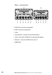
two ports on HDS-9 & 12, one on 7 5 NMEA 2000 8 | HDS Gen2 Touch overview | HDS Gen2 Touch Installation Manual connects to LSS-2 HD Transducer 3 Power - also video for HDS-9 & 12, with optional adaptor 4 Ethernet - connectors A B 1 2 3445 451 2 3 A HDS-9 & 12 connector arrangement B HDS-7 connector arrangement 1 Sonar 2 StructureScan - Rear -
two ports on HDS-9 & 12, one on 7 5 NMEA 2000 8 | HDS Gen2 Touch overview | HDS Gen2 Touch Installation Manual connects to LSS-2 HD Transducer 3 Power - also video for HDS-9 & 12, with optional adaptor 4 Ethernet - connectors A B 1 2 3445 451 2 3 A HDS-9 & 12 connector arrangement B HDS-7 connector arrangement 1 Sonar 2 StructureScan - Rear -
Installation Manual
Page 11
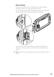
SD card slot Used for optional Navionics or InsightHD chart data, software updates, transfer of user data and system backup. The card reader door is opened by lightly pressing and sliding the door to prevent possible water ingress. ¼¼ Note: The HDS-9 and 12 Displays have two card readers, the HDS-7 has one. The card reader door should always be shut immediately after inserting or removing a card, in order to the left, then pulling forward from the left side. HDS Gen2 Touch overview | HDS Gen2 Touch Installation Manual | 9
SD card slot Used for optional Navionics or InsightHD chart data, software updates, transfer of user data and system backup. The card reader door is opened by lightly pressing and sliding the door to prevent possible water ingress. ¼¼ Note: The HDS-9 and 12 Displays have two card readers, the HDS-7 has one. The card reader door should always be shut immediately after inserting or removing a card, in order to the left, then pulling forward from the left side. HDS Gen2 Touch overview | HDS Gen2 Touch Installation Manual | 9
Installation Manual
Page 14
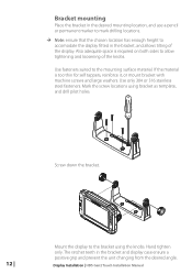
Use only 304 or 316 stainless steel fasteners. Display Installation | HDS Gen2 Touch Installation Manual Bracket mounting Place the bracket in the desired mounting location, and use a pencil or permanent marker to mark drilling locations. ¼¼ Note: ...ensure that the chosen location has enough height to allow tightening and loosening of the display. Screw down the bracket. 12 | Mount the display to the mounting surface material. Also adequate space is too thin for self tappers, reinforce it, or mount bracket with machine screws...
Use only 304 or 316 stainless steel fasteners. Display Installation | HDS Gen2 Touch Installation Manual Bracket mounting Place the bracket in the desired mounting location, and use a pencil or permanent marker to mark drilling locations. ¼¼ Note: ...ensure that the chosen location has enough height to allow tightening and loosening of the display. Screw down the bracket. 12 | Mount the display to the mounting surface material. Also adequate space is too thin for self tappers, reinforce it, or mount bracket with machine screws...
Installation Manual
Page 15
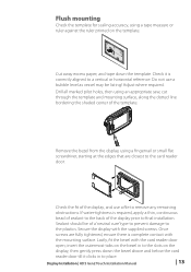
Adjust where required. Display Installation | HDS Gen2 Touch Installation Manual | 13 Check the fit of the template. Once screws are closest to the plastics. insert the outermost tabs on the bezel in to ... SCREW CL 110.2 mm (3.75") 99.5 mm (3.92") 95.3 mm (7.50") PRODUCSTUNOUCTOLVINEER 190.5 mm (7.50") 199.0 mm (7.83") 220.4 mm (8.68") Check dimensions before cutting 12" CL Cut away excess paper, and tape down the bezel above and below the card reader door till it is required, apply a thin, continuous bead...
Adjust where required. Display Installation | HDS Gen2 Touch Installation Manual | 13 Check the fit of the template. Once screws are closest to the plastics. insert the outermost tabs on the bezel in to ... SCREW CL 110.2 mm (3.75") 99.5 mm (3.92") 95.3 mm (7.50") PRODUCSTUNOUCTOLVINEER 190.5 mm (7.50") 199.0 mm (7.83") 220.4 mm (8.68") Check dimensions before cutting 12" CL Cut away excess paper, and tape down the bezel above and below the card reader door till it is required, apply a thin, continuous bead...
Installation Manual
Page 19
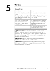
Warning: The positive supply wire (red) should always be sure to turn electrical power off. Wiring | HDS Gen2 Touch Installation Manual | 17 Warning: The HDS Gen2 Touch has a voltage rating of the power supply is not suited for use with 24V DC systems. ! 5 Wiring Guidelines Don't do this Do this...Be sure that allows water to flow down into the connectors Don't route the data cables in a way that the voltage of 12 V DC, it is compatible with the HDS Gen2 Touch display ! If power is left on or turned on during the installation, fire, electrical shock, or other serious injury may ...
Warning: The positive supply wire (red) should always be sure to turn electrical power off. Wiring | HDS Gen2 Touch Installation Manual | 17 Warning: The HDS Gen2 Touch has a voltage rating of the power supply is not suited for use with 24V DC systems. ! 5 Wiring Guidelines Don't do this Do this...Be sure that allows water to flow down into the connectors Don't route the data cables in a way that the voltage of 12 V DC, it is compatible with the HDS Gen2 Touch display ! If power is left on or turned on during the installation, fire, electrical shock, or other serious injury may ...
Installation Manual
Page 20
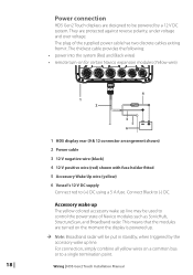
...cable has two discrete cables exiting from it. Connect Black to (+) DC using a 5 A fuse. Wiring | HDS Gen2 Touch Installation Manual This means that the modules are protected against reverse polarity, under voltage and over voltage. The thickest cable... 2 3 5 6 _+ 1 HDS display rear (9 & 12 connector arrangement shown) 2 Power cable 3 12 V negative wire (black) 4 12 V positive wire (red) shown with fuse holder fitted 5 Accessory Wake Up wire (yellow) 6 Vessel's 12 V DC supply Connect red to (-) DC. Power connection HDS Gen2 Touch displays are designed to a single termination...
...cable has two discrete cables exiting from it. Connect Black to (+) DC using a 5 A fuse. Wiring | HDS Gen2 Touch Installation Manual This means that the modules are protected against reverse polarity, under voltage and over voltage. The thickest cable... 2 3 5 6 _+ 1 HDS display rear (9 & 12 connector arrangement shown) 2 Power cable 3 12 V negative wire (black) 4 12 V positive wire (red) shown with fuse holder fitted 5 Accessory Wake Up wire (yellow) 6 Vessel's 12 V DC supply Connect red to (-) DC. Power connection HDS Gen2 Touch displays are designed to a single termination...
Installation Manual
Page 21
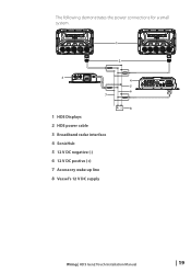
The following demonstrates the power connections for a small system. 1 2 3 7 1 HDS Displays 2 HDS power cable 3 Broadband radar interface 4 SonicHub 5 12 V DC negative (-) 6 12 V DC postive (+) 7 Accessory wake up line 8 Vessel's 12 V DC supply 4 5 6 +_ 8 Wiring | HDS Gen2 Touch Installation Manual | 19
The following demonstrates the power connections for a small system. 1 2 3 7 1 HDS Displays 2 HDS power cable 3 Broadband radar interface 4 SonicHub 5 12 V DC negative (-) 6 12 V DC postive (+) 7 Accessory wake up line 8 Vessel's 12 V DC supply 4 5 6 +_ 8 Wiring | HDS Gen2 Touch Installation Manual | 19
Installation Manual
Page 22
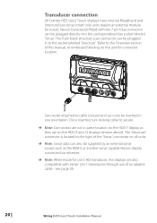
..., or embossed labeling on the HDS-9 and 12 displays (shown above). The 'Structure' connector is keyed and can be inserted in one orientation. Refer to cable is located to the socket labelled 'Structure' . Transducer connection All Combo HDS Gen2 Touch displays have internal Broadband and StructureScan... pin blue connector can only be plugged directly into the corresponding blue socket labeled 'Sonar'. see page 30. 20 | Wiring | HDS Gen2 Touch Installation Manual Connector attached to the Overview section of the 'Sonar' connector on all units. ¼¼ Note: Sonar data can...
..., or embossed labeling on the HDS-9 and 12 displays (shown above). The 'Structure' connector is keyed and can be inserted in one orientation. Refer to cable is located to the socket labelled 'Structure' . Transducer connection All Combo HDS Gen2 Touch displays have internal Broadband and StructureScan... pin blue connector can only be plugged directly into the corresponding blue socket labeled 'Sonar'. see page 30. 20 | Wiring | HDS Gen2 Touch Installation Manual Connector attached to the Overview section of the 'Sonar' connector on all units. ¼¼ Note: Sonar data can...

Installation Manual
Page 23
... to multiple devices If connecting more NEP-2 modules together to provide the required ports. Navico ethernet cables have two. Wiring | HDS Gen2 Touch Installation Manual | 21 Ethernet device connection Ethernet is auto sensing, meaning that the unit can connect to one network device directly,... without the use the optional network expansion Port (NEP-2). The HDS-7 display has one ethernet port, whereas the HDS-9 and 12 displays have a locking collar, for linking multiple NEP-2 modules together. If the number of ethernet devices...
... to multiple devices If connecting more NEP-2 modules together to provide the required ports. Navico ethernet cables have two. Wiring | HDS Gen2 Touch Installation Manual | 21 Ethernet device connection Ethernet is auto sensing, meaning that the unit can connect to one network device directly,... without the use the optional network expansion Port (NEP-2). The HDS-7 display has one ethernet port, whereas the HDS-9 and 12 displays have a locking collar, for linking multiple NEP-2 modules together. If the number of ethernet devices...
Installation Manual
Page 24
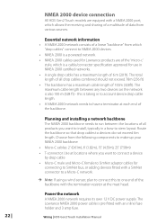
...length. • A NMEA 2000 network needs to have a terminator at the mast head. Power the network A NMEA 2000 network requires its own 12 V DC power supply. Choose from which "drop cables" connect to stern layout. The total length of all products you want to install, typically... 2000 devices • NMEA 2000 is a powered network. • NMEA 2000 cables used for Lowrance products are equiped with an inline fuse holder and 3 amp fuse. 22 | Wiring | HDS Gen2 Touch Installation Manual The maximum cable length between the locations of all drop cables combined should not exceed 78m...
...length. • A NMEA 2000 network needs to have a terminator at the mast head. Power the network A NMEA 2000 network requires its own 12 V DC power supply. Choose from which "drop cables" connect to stern layout. The total length of all products you want to install, typically... 2000 devices • NMEA 2000 is a powered network. • NMEA 2000 cables used for Lowrance products are equiped with an inline fuse holder and 3 amp fuse. 22 | Wiring | HDS Gen2 Touch Installation Manual The maximum cable length between the locations of all drop cables combined should not exceed 78m...
Installation Manual
Page 25
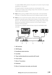
The following diagram demonstrates a typical small NMEA 2000 network: 1 2 3 5 _+ 12 V DC 6 T 9 7 8 1 GPS antenna 2 HDS Display 3 Broadband radar interface 4 SonicHub 5 'Drop' cables (should not exceed 6m (20') each) 6 Power cable 7 Micro-C T junctions 8 Backbone 9 Micro-C terminator (one male, one female) 4 T 9 Wiring | HDS Gen2 Touch Installation Manual | 23 Avoid connection to the same terminals as the autopilot computer, pulse...
The following diagram demonstrates a typical small NMEA 2000 network: 1 2 3 5 _+ 12 V DC 6 T 9 7 8 1 GPS antenna 2 HDS Display 3 Broadband radar interface 4 SonicHub 5 'Drop' cables (should not exceed 6m (20') each) 6 Power cable 7 Micro-C T junctions 8 Backbone 9 Micro-C terminator (one male, one female) 4 T 9 Wiring | HDS Gen2 Touch Installation Manual | 23 Avoid connection to the same terminals as the autopilot computer, pulse...

Installation Manual
Page 27
...finite, and depends on the receiving hardware. Connecting video sources 12 V DC 1 2 3 4 1 Video input adaptor cable 2 RCA plug 3 12 V camera (3rd party) 4 HDS power/data cable ¼¼ Note: Only connect NTSC and PAL video sources Wiring | HDS Gen2 Touch Installation Manual | 25 Talkers and Listeners Do not connect multiple...on the unit, and the plug on the unit connected to the input (Rx) of receivers is possible. Video In On the HDS-9 and HDS-12, a video camera may drive multiple receivers (Listeners). The number of the unit. The output however may be corrupted if more ...
...finite, and depends on the receiving hardware. Connecting video sources 12 V DC 1 2 3 4 1 Video input adaptor cable 2 RCA plug 3 12 V camera (3rd party) 4 HDS power/data cable ¼¼ Note: Only connect NTSC and PAL video sources Wiring | HDS Gen2 Touch Installation Manual | 25 Talkers and Listeners Do not connect multiple...on the unit, and the plug on the unit connected to the input (Rx) of receivers is possible. Video In On the HDS-9 and HDS-12, a video camera may drive multiple receivers (Listeners). The number of the unit. The output however may be corrupted if more ...
Installation Manual
Page 31
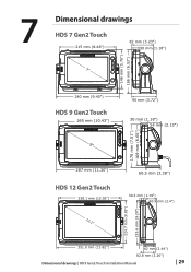
7 Dimensional drawings HDS 7 Gen2 Touch 215 mm (8.48") 82 mm (3.23") 30 mm (1.18") 7" 146 mm (5.76") 166 mm (6.52") 240 mm (9.45") HDS 9 Gen2 Touch 265 mm (10.43") 9" 95 mm (3.72") 30 mm (1.18") 54 mm (2.13") 178 mm (7.01") 169 mm (6.65") 287 mm (11.30") HDS 12 Gen2 Touch 328.1 mm (12.92") 12.1" 60.5 mm (2.38") 30.3 mm (1.19") 60.9 mm (2.4") 224.7 mm (8.85") 233.6 mm (9.20") 351.0 mm (13.82") 62 mm (2.44") 82.8 mm (3.26") Dimensional drawings | HDS Gen2 Touch Installation Manual | 29
7 Dimensional drawings HDS 7 Gen2 Touch 215 mm (8.48") 82 mm (3.23") 30 mm (1.18") 7" 146 mm (5.76") 166 mm (6.52") 240 mm (9.45") HDS 9 Gen2 Touch 265 mm (10.43") 9" 95 mm (3.72") 30 mm (1.18") 54 mm (2.13") 178 mm (7.01") 169 mm (6.65") 287 mm (11.30") HDS 12 Gen2 Touch 328.1 mm (12.92") 12.1" 60.5 mm (2.38") 30.3 mm (1.19") 60.9 mm (2.4") 224.7 mm (8.85") 233.6 mm (9.20") 351.0 mm (13.82") 62 mm (2.44") 82.8 mm (3.26") Dimensional drawings | HDS Gen2 Touch Installation Manual | 29
Installation Manual
Page 33
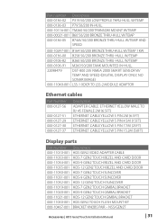
...-001 000-11019-001 000-11020-001 000-11021-001 000-11050-001 000-10467-001 Description HDS GEN2 VIDEO ADAPTER CABLE HDS-7 GEN2 TOUCH BEZEL AND CARD DOOR HDS-9 GEN2 TOUCH BEZEL AND CARD DOOR HDS-12 GEN2 TOUCH BEZEL AND CARD DOOR HDS-7 GEN2 TOUCH SUNCOVER HDS-9 GEN2 TOUCH SUNCOVER HDS-12 GEN2 TOUCH SUNCOVER HDS-7 GEN2 TOUCH GIMBAL BRACKET HDS-9 GEN2 TOUCH GIMBAL BRACKET HDS-12 GEN2 TOUCH GIMBAL BRACKET HDS GEN2 TOUCH FLUSH MOUNT KIT BRACKET KNOBS PAIR - NSS/GEN2T Accessories...
...-001 000-11019-001 000-11020-001 000-11021-001 000-11050-001 000-10467-001 Description HDS GEN2 VIDEO ADAPTER CABLE HDS-7 GEN2 TOUCH BEZEL AND CARD DOOR HDS-9 GEN2 TOUCH BEZEL AND CARD DOOR HDS-12 GEN2 TOUCH BEZEL AND CARD DOOR HDS-7 GEN2 TOUCH SUNCOVER HDS-9 GEN2 TOUCH SUNCOVER HDS-12 GEN2 TOUCH SUNCOVER HDS-7 GEN2 TOUCH GIMBAL BRACKET HDS-9 GEN2 TOUCH GIMBAL BRACKET HDS-12 GEN2 TOUCH GIMBAL BRACKET HDS GEN2 TOUCH FLUSH MOUNT KIT BRACKET KNOBS PAIR - NSS/GEN2T Accessories...
Installation Manual
Page 37
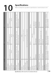
...HDS Gen2 Touch Installation Manual Multi Function Display Display Display resolution Display type Display brightness Touch screen Power Power supply Power consumption Technical / Environmental Housing Temperature Waterproof standard Declaration of conformity Interface Ethernet NMEA2000 Video input Data card slot Other Weight (display only) Pack dimensions (L x W x H) Pack weight Echo sounder Sonar frequency Sonar output power HDS-7 HDS-9 HDS-12...F to specifications: www.lowrance.com single channel 2x SD (full size) 2x SD (full size) 1.6 kg (3.5 lb) 30.5 x 27.9 x 27.9 cm (12" x 11" x 11...
...HDS Gen2 Touch Installation Manual Multi Function Display Display Display resolution Display type Display brightness Touch screen Power Power supply Power consumption Technical / Environmental Housing Temperature Waterproof standard Declaration of conformity Interface Ethernet NMEA2000 Video input Data card slot Other Weight (display only) Pack dimensions (L x W x H) Pack weight Echo sounder Sonar frequency Sonar output power HDS-7 HDS-9 HDS-12...F to specifications: www.lowrance.com single channel 2x SD (full size) 2x SD (full size) 1.6 kg (3.5 lb) 30.5 x 27.9 x 27.9 cm (12" x 11" x 11...


