SL930 Addendum Manual
Page 1
... setting the Right/Left switch on the left side of the control board. 5. Disconnect the brown and red wires from the factory equipped with battery run, field installation of the wires. 3. Connect a green wire from 13 and 14. Existing Bridge Rectifier 01-34563 © 2008, The... 2 operation is no longer supported. Figure 4 Disconnect these existing wires from terminal 2 to terminal 15 of the control board. 4. Addendum For SL930 This addendum is to be set in conjunction with the owner's manual. The illustration at right shows additional wiring required for all mounting and wiring...
... setting the Right/Left switch on the left side of the control board. 5. Disconnect the brown and red wires from the factory equipped with battery run, field installation of the wires. 3. Connect a green wire from 13 and 14. Existing Bridge Rectifier 01-34563 © 2008, The... 2 operation is no longer supported. Figure 4 Disconnect these existing wires from terminal 2 to terminal 15 of the control board. 4. Addendum For SL930 This addendum is to be set in conjunction with the owner's manual. The illustration at right shows additional wiring required for all mounting and wiring...
SL930 Manual
Page 2
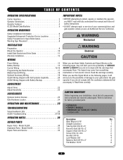
..."D6 VxV3E"ERRTTEENNCCIIAA 4 4 8 ADVERTENCIA PRECAUCIÓN 2 Read the warnings carefully. Model SL930 30 Illustrated Parts - OPERATION AND MAINTENANCE 25 TROUBLESHOOTING Visual Feedback LEDs 26 SL930 Troubleshooting 27-28 • OPERATOR • OWNER'S MANUAL • HARDWARE KIT SL930 (K77-40335) Complete with Battery Backup 21 ADJUSTMENT AVERTISSEMENT Adjust Timer 22 Adjust Sensitivity 22 ACACETSSTOERINESTION Optional...
..."D6 VxV3E"ERRTTEENNCCIIAA 4 4 8 ADVERTENCIA PRECAUCIÓN 2 Read the warnings carefully. Model SL930 30 Illustrated Parts - OPERATION AND MAINTENANCE 25 TROUBLESHOOTING Visual Feedback LEDs 26 SL930 Troubleshooting 27-28 • OPERATOR • OWNER'S MANUAL • HARDWARE KIT SL930 (K77-40335) Complete with Battery Backup 21 ADJUSTMENT AVERTISSEMENT Adjust Timer 22 Adjust Sensitivity 22 ACACETSSTOERINESTION Optional...
SL930 Manual
Page 14
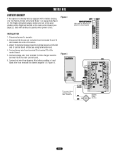
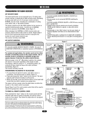
... from terminals 13 and 14 and insulate the ends of control board and secure using terminal screws. 4. Connect red wire from terminal A to battery positive (+) and black wire from terminal B to be set in the same position as RIGHT/LEFT switch on the left side of the wires.... 3. The Right/Left switch simply needs to battery negative (-) (Figure 4). Disconnect power to operate when power is already factory equipped with a battery backup, only the Right/Left Side switch and Mode 1 are supported (Figure 3). Connect green wire from...
... from terminals 13 and 14 and insulate the ends of control board and secure using terminal screws. 4. Connect red wire from terminal A to battery positive (+) and black wire from terminal B to be set in the same position as RIGHT/LEFT switch on the left side of the wires.... 3. The Right/Left switch simply needs to battery negative (-) (Figure 4). Disconnect power to operate when power is already factory equipped with a battery backup, only the Right/Left Side switch and Mode 1 are supported (Figure 3). Connect green wire from...
SL930 Manual
Page 17
... are prohibited, except for 30 seconds. 3. With the jumper in "C" (Constant) position, the contacts will glow steadily for changing the code setting or replacing the battery. WPithRin E30CsecAondUs,CApreITsÓsTanNEd hNoldTthIeObutNton on residential garage door openers because it can be used with up to Comply with FCC Standards FOR HOME...
... are prohibited, except for 30 seconds. 3. With the jumper in "C" (Constant) position, the contacts will glow steadily for changing the code setting or replacing the battery. WPithRin E30CsecAondUs,CApreITsÓsTanNEd hNoldTthIeObutNton on residential garage door openers because it can be used with up to Comply with FCC Standards FOR HOME...
SL930 Manual
Page 21
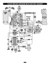
SL930 WIRING DIAGRAM WITH BATTERY BACKUP 90 VDC 21
SL930 WIRING DIAGRAM WITH BATTERY BACKUP 90 VDC 21
SL930 Manual
Page 27
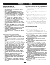
... be stuck. 8. A stuck transmitter may need adjustment. If a remote control is being used try another push button or a remote control. 3. Check the battery inside of them may be stuck on the circuit board. If a click is heard while the remote control is being used to the stop input... to make sure it is in the fully open the gate, try another remote control or try using another remote control. 2. TROUBLESHOOTING SL930 TROUBLESHOOTING REMOTE CONTROL DOES NOT WORK 1. Check to lubricate any mechanical parts on the gate including wheels and rollers and clean the track ...
... be stuck. 8. A stuck transmitter may need adjustment. If a remote control is being used try another push button or a remote control. 3. Check the battery inside of them may be stuck on the circuit board. If a click is heard while the remote control is being used to the stop input... to make sure it is in the fully open the gate, try another remote control or try using another remote control. 2. TROUBLESHOOTING SL930 TROUBLESHOOTING REMOTE CONTROL DOES NOT WORK 1. Check to lubricate any mechanical parts on the gate including wheels and rollers and clean the track ...
SL930 Manual
Page 30
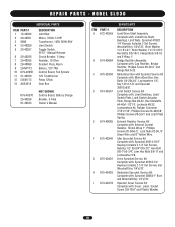
...: Sprocket 35B54-1" Bore and Woodruff Key 1/4"x7/8". Limit Switch Service Kit Complete with : Sprocket 41B18-1/4" Keyway Includes 2 1/4" Set Screws and Woodruff Key 1/4"x7/8". MODEL SL930 INDIVIDUAL PARTS ITEM PART # 1 13-40362 2 20-40351 3 9596 4 23-40050 5 23-40357 6 25-40356 7 29-40355 8 29-40089 9 29-NP712... Screws #4-40x5/8", Phillips Screws #8-32x1" and Limit Plate Spring. Manual Release Circuit Breaker, 5 Amp Resistor, 10 Ohm Sonalert Piezo Alarm Battery, 12V 7AH Control Board, Full System 12V Transformer Relay 12Vdc Gear Box K79-40370 25-40356 01-40333 NOT SHOWN Control Board...
...: Sprocket 35B54-1" Bore and Woodruff Key 1/4"x7/8". Limit Switch Service Kit Complete with : Sprocket 41B18-1/4" Keyway Includes 2 1/4" Set Screws and Woodruff Key 1/4"x7/8". MODEL SL930 INDIVIDUAL PARTS ITEM PART # 1 13-40362 2 20-40351 3 9596 4 23-40050 5 23-40357 6 25-40356 7 29-40355 8 29-40089 9 29-NP712... Screws #4-40x5/8", Phillips Screws #8-32x1" and Limit Plate Spring. Manual Release Circuit Breaker, 5 Amp Resistor, 10 Ohm Sonalert Piezo Alarm Battery, 12V 7AH Control Board, Full System 12V Transformer Relay 12Vdc Gear Box K79-40370 25-40356 01-40333 NOT SHOWN Control Board...

