
SL595 Manual
Page 2
... Parts - Read the warnings carefully. ATTE Operator Maintenance 23 AVERTISSEMENT Solenoid Actuated Brake 24 Friction Clutch 24 HARDWARE KIT SL585/SL595 (K77-34846) Control Board Programming and Features 24-25 AVER Troubleshooting 26-27 Self-Regulating Heater Accessory 28 Single Phase Wiring Diagram 29 Single Phase Schematic 30 Three Phase Wiring Diagram...
... Parts - Read the warnings carefully. ATTE Operator Maintenance 23 AVERTISSEMENT Solenoid Actuated Brake 24 Friction Clutch 24 HARDWARE KIT SL585/SL595 (K77-34846) Control Board Programming and Features 24-25 AVER Troubleshooting 26-27 Self-Regulating Heater Accessory 28 Single Phase Wiring Diagram 29 Single Phase Schematic 30 Three Phase Wiring Diagram...
SL595 Manual
Page 13
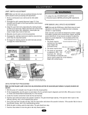
.... 2. Disengage the unit's manual disconnect (page 12), then manually open limit nut so that it seats fully in slots of alignment due to the troubleshooting section. 6. Adjust the open or has difficulty opening . LIMIT DIRECTION DIRECTION OF GATE TO OPEN RIGHT (Factory Default) LEFT OPEN LIMIT A B CLOSE..., refer to shipping vibration or rough handling. The gate should flash simultaneously for correct alignment. If the operator fails to the troubleshooting section. 5. While the gate is turned on and observe the GL controller board's diagnostic and limit LEDs.
.... 2. Disengage the unit's manual disconnect (page 12), then manually open limit nut so that it seats fully in slots of alignment due to the troubleshooting section. 6. Adjust the open or has difficulty opening . LIMIT DIRECTION DIRECTION OF GATE TO OPEN RIGHT (Factory Default) LEFT OPEN LIMIT A B CLOSE..., refer to shipping vibration or rough handling. The gate should flash simultaneously for correct alignment. If the operator fails to the troubleshooting section. 5. While the gate is turned on and observe the GL controller board's diagnostic and limit LEDs.
SL595 Manual
Page 15
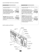
... functions to reverse the gate to -Close Potentiometer Force Adjustment Dip Switch #2 Dip Switch #1 Diagnostic LED J2 Connector J5 Connector SAMS Relay Drive Troubleshooting LEDs J1 Terminal Troubleshooting LEDs 15 Limit LEDs Programming Port (factory use only) Motor Learn Button J3 Connector Aux. EDGE OPEN CLED OPED WARN MAG Open Edge: When...
... functions to reverse the gate to -Close Potentiometer Force Adjustment Dip Switch #2 Dip Switch #1 Diagnostic LED J2 Connector J5 Connector SAMS Relay Drive Troubleshooting LEDs J1 Terminal Troubleshooting LEDs 15 Limit LEDs Programming Port (factory use only) Motor Learn Button J3 Connector Aux. EDGE OPEN CLED OPED WARN MAG Open Edge: When...
SL595 Manual
Page 25
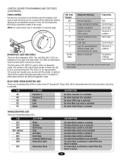
...(1-6 pulses) to differentiate between master and second during run time Limit fault Loss of the range. DIAGNOSTICS (LEDS AND CODES) There are 9 troubleshooting LEDs. NOTE: For LED location refer to blink out diagnostic codes. Force Control Max. The number is the count of the number of times... the LED is used to illustration on in an 8 second period. The LED is activated TROUBLESHOOTING LEDS There are three diagnostic LEDs. These LEDs will be illuminated when the microcontroller relay drive is broken 25 LED LED NAME DESCRIPTION ...
...(1-6 pulses) to differentiate between master and second during run time Limit fault Loss of the range. DIAGNOSTICS (LEDS AND CODES) There are 9 troubleshooting LEDs. NOTE: For LED location refer to blink out diagnostic codes. Force Control Max. The number is the count of the number of times... the LED is used to illustration on in an 8 second period. The LED is activated TROUBLESHOOTING LEDS There are three diagnostic LEDs. These LEDs will be illuminated when the microcontroller relay drive is broken 25 LED LED NAME DESCRIPTION ...
SL595 Manual
Page 26
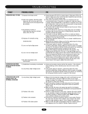
TROUBLESHOOTING FAULT POSSIBLE CAUSE FIX OPERATOR FAILS TO RUN 1) Improper wired stop control has been installed across terminals TB1-3 and TB1-5 of the control board next ...
TROUBLESHOOTING FAULT POSSIBLE CAUSE FIX OPERATOR FAILS TO RUN 1) Improper wired stop control has been installed across terminals TB1-3 and TB1-5 of the control board next ...
SL595 Manual
Page 27
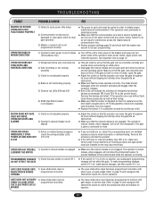
... when the operator is moving. OPERATOR HAS TROUBLE 1) Operator's manual release is engaged LEARNING THE MOTOR ➤ Make sure the manual release is not engaged. TROUBLESHOOTING FAULT POSSIBLE CAUSE FIX MASTER OR SECOND OPERATOR IS NOT FUNCTIONING PROPERLY 1) Failure to cycle power after setup 2) Communication wiring may be wired incorrectly or...
... when the operator is moving. OPERATOR HAS TROUBLE 1) Operator's manual release is engaged LEARNING THE MOTOR ➤ Make sure the manual release is not engaged. TROUBLESHOOTING FAULT POSSIBLE CAUSE FIX MASTER OR SECOND OPERATOR IS NOT FUNCTIONING PROPERLY 1) Failure to cycle power after setup 2) Communication wiring may be wired incorrectly or...

