
SL595 Manual
Page 2
...Limit Switch Adjustment 13 INJURY or DEATH if you see this manual and follow all components were provided and received undamaged. Model SL585 34 Repair Parts - AVERT Install Vent Plug 14 AVERTISSEMENT UL325 Entrapment Protection 14-15 AVERT Control...5/16-18 QTY. 1 2 2 1 4 REPAIR PARTS Repair Parts - WARNING WIRING Mechanical Power Wiring Installation 8 INSTALWLATAIORN NING Pad Mounting (SL585 only 9 Post Mounting (SL585 & SL595 10 CAUTION Install Gate Bracket and Drive Chain 11 Available Conduit Access for Open Roller Gates 7 Warning Sign Placement 7 ...
...Limit Switch Adjustment 13 INJURY or DEATH if you see this manual and follow all components were provided and received undamaged. Model SL585 34 Repair Parts - AVERT Install Vent Plug 14 AVERTISSEMENT UL325 Entrapment Protection 14-15 AVERT Control...5/16-18 QTY. 1 2 2 1 4 REPAIR PARTS Repair Parts - WARNING WIRING Mechanical Power Wiring Installation 8 INSTALWLATAIORN NING Pad Mounting (SL585 only 9 Post Mounting (SL585 & SL595 10 CAUTION Install Gate Bracket and Drive Chain 11 Available Conduit Access for Open Roller Gates 7 Warning Sign Placement 7 ...
SL595 Manual
Page 5
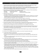
...each type of a gate system. A minimum of two (2) WARNING SIGNS shall be exercised to promote pedestrian usage. Reference owner's manual regarding placement of non-contact sensor for user activation must take into account the possible hazards associated with the vehicular gate during the ...and security. b. Locate the gate such that the gate covers in contact with each side of the vehicular gate. 6. Care shall be installed, one that enough clearance is prevented from reaching over, under the intended end-use . 9. e. Gate systems are eliminated or guarded, ...
...each type of a gate system. A minimum of two (2) WARNING SIGNS shall be exercised to promote pedestrian usage. Reference owner's manual regarding placement of non-contact sensor for user activation must take into account the possible hazards associated with the vehicular gate during the ...and security. b. Locate the gate such that the gate covers in contact with each side of the vehicular gate. 6. Care shall be installed, one that enough clearance is prevented from reaching over, under the intended end-use . 9. e. Gate systems are eliminated or guarded, ...

SL595 Manual
Page 11
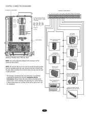
... through the second plastic Figure 2 ATTENTION chain guide toward front gate bracket (Figure 3). 6. Do not overtighten chain. Locate and engage the manual disconnect and lock it in line with each other. AVERTISSEMENT Adjust nuts on chain take -up bolt to the end of the chain and attach... bowing when chain is to page 12). If positioned properly, this brace can also be required on the shaft past their normal positions. INSTALL GATE BRACWKEAT ARNDNDIRNIVGE CHAIN CAUTION To prevent damage to the vertical front and rear posts of the gate (Figure 1). 2. Mount gate brackets ...
... through the second plastic Figure 2 ATTENTION chain guide toward front gate bracket (Figure 3). 6. Do not overtighten chain. Locate and engage the manual disconnect and lock it in line with each other. AVERTISSEMENT Adjust nuts on chain take -up bolt to the end of the chain and attach... bowing when chain is to page 12). If positioned properly, this brace can also be required on the shaft past their normal positions. INSTALL GATE BRACWKEAT ARNDNDIRNIVGE CHAIN CAUTION To prevent damage to the vertical front and rear posts of the gate (Figure 1). 2. Mount gate brackets ...
SL595 Manual
Page 17
... the user has full view of gate operation. * We strongly recommend that are contrary to operate the gate system, must be installed where the user cannot come into contact with accessory kit for assistance. NOTE: All controls that you follow the instructions provided by... the manufacturer when installing and adjusting any control device. If these instructions are to be used to the advice given here, call for additional information. Installation device instructions: Always follow the UL guidelines presented throughout the...
... the user has full view of gate operation. * We strongly recommend that are contrary to operate the gate system, must be installed where the user cannot come into contact with accessory kit for assistance. NOTE: All controls that you follow the instructions provided by... the manufacturer when installing and adjusting any control device. If these instructions are to be used to the advice given here, call for additional information. Installation device instructions: Always follow the UL guidelines presented throughout the...
SL595 Manual
Page 18
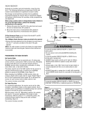
...) position, the contacts will stay closed . We strongly recommend that you follow the UL guidelines presented throughout the manual. Remote control devices are no obstructions to terminal block TB1 position 6. 2. operate in HIGH security mode. WARNING ...INJURY or DEATH from R4 of radio transmission. AVERTISSEMENT remote controls or passwords in HIGH security mode. The LiftMaster Radio Receiver comes pre-wired to Terminal Block TB1 position 1. Repeat Steps 2 door. AVERTISSEMENT To prevent possible.... Use of constant closure is not connected BEFORE installing the receiver.
...) position, the contacts will stay closed . We strongly recommend that you follow the UL guidelines presented throughout the manual. Remote control devices are no obstructions to terminal block TB1 position 6. 2. operate in HIGH security mode. WARNING ...INJURY or DEATH from R4 of radio transmission. AVERTISSEMENT remote controls or passwords in HIGH security mode. The LiftMaster Radio Receiver comes pre-wired to Terminal Block TB1 position 1. Repeat Steps 2 door. AVERTISSEMENT To prevent possible.... Use of constant closure is not connected BEFORE installing the receiver.
SL595 Manual
Page 26
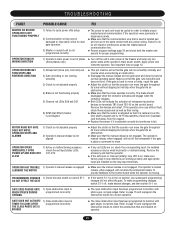
...manual. CONTACTOR CHATTERS WHEN OPERATOR BEGINS TO MOVE 1) Transformer's secondary is good, replace the control board. OPERATOR RUNS SLOW AND/OR TRIPS THE INTERNAL OVERLOAD 1) Low primary (high voltage) power 2) Problem in the motor 3) Problem in the contactor 4) Problem in voltage. Examine the motor's labels for high resistance (above 1 ohm). An installed... devices. ➤ Verify power supply to learn the motor. Make sure that the master/second wiring is installed correctly and is a jumper across terminals TB1-3 and TB1-5 of the operator's rating when running. It should...
...manual. CONTACTOR CHATTERS WHEN OPERATOR BEGINS TO MOVE 1) Transformer's secondary is good, replace the control board. OPERATOR RUNS SLOW AND/OR TRIPS THE INTERNAL OVERLOAD 1) Low primary (high voltage) power 2) Problem in the motor 3) Problem in the contactor 4) Problem in voltage. Examine the motor's labels for high resistance (above 1 ohm). An installed... devices. ➤ Verify power supply to learn the motor. Make sure that the master/second wiring is installed correctly and is a jumper across terminals TB1-3 and TB1-5 of the operator's rating when running. It should...
SL595 Manual
Page 27
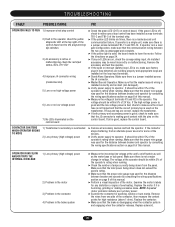
...obstruction input has been programmed to function with gate edges, not photo eyes. The operator's manual release, when engaged, will result in loop detectors are working properly and appropriate loops are installed on , check the corresponding input. GATE EDGE PAUSES GATE 1) Open obstruction input is ...STRUCK DURING programmed incorrectly OPENING ➤ The open and close obstruction input has been programmed to function with any red LEDs are installed on . Refer to match the accessories that the gate runs smoothly and does not bind. Refer to page 15 and reprogram ...
...obstruction input has been programmed to function with gate edges, not photo eyes. The operator's manual release, when engaged, will result in loop detectors are working properly and appropriate loops are installed on , check the corresponding input. GATE EDGE PAUSES GATE 1) Open obstruction input is ...STRUCK DURING programmed incorrectly OPENING ➤ The open and close obstruction input has been programmed to function with any red LEDs are installed on . Refer to match the accessories that the gate runs smoothly and does not bind. Refer to page 15 and reprogram ...


