
SL595 Manual
Page 2
...Manual Disconnect 12 When you see this manual and follow all components were provided and received undamaged. Model SL585 34 Repair Parts - WARNING WIRING Mechanical Power Wiring Installation 8 INSTALWLATAIORN NING Pad Mounting (SL585 only 9 Post Mounting (SL585 & SL595 10 CAUTION Install Gate...21"C6TEIAÓNDNCVIAERTENCIA 8 8 4 4 Antenna ADVERTENCIA1 PRECAUCIÓN 2 Model SL585 33 Illustrated Parts - Model SL595 35 Illustrated Parts - Refer to your gate and/or the gate operator if you do not comply with the cautionary statements that all safety instructions.
...Manual Disconnect 12 When you see this manual and follow all components were provided and received undamaged. Model SL585 34 Repair Parts - WARNING WIRING Mechanical Power Wiring Installation 8 INSTALWLATAIORN NING Pad Mounting (SL585 only 9 Post Mounting (SL585 & SL595 10 CAUTION Install Gate...21"C6TEIAÓNDNCVIAERTENCIA 8 8 4 4 Antenna ADVERTENCIA1 PRECAUCIÓN 2 Model SL585 33 Illustrated Parts - Model SL595 35 Illustrated Parts - Refer to your gate and/or the gate operator if you do not comply with the cautionary statements that all safety instructions.
SL595 Manual
Page 5
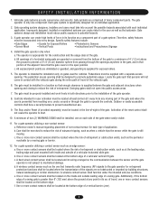
... associated with a separate access opening shall be located in that portion of a vehicular vertical lift gate. c. Reference owner's manual regarding placement of entrapment or obstruction exists, such as the perimeter reachable by building structures, natural ...in both inside and outside of the gate operator. 8. Outdoor or easily accessible controls shall have a security feature to the installation of a vehicular horizontal slide gate. b. d. For a gate operator utilizing a non-contact sensor: a. Gate operating system designers, installers and users must...
... associated with a separate access opening shall be located in that portion of a vehicular vertical lift gate. c. Reference owner's manual regarding placement of entrapment or obstruction exists, such as the perimeter reachable by building structures, natural ...in both inside and outside of the gate operator. 8. Outdoor or easily accessible controls shall have a security feature to the installation of a vehicular horizontal slide gate. b. d. For a gate operator utilizing a non-contact sensor: a. Gate operating system designers, installers and users must...

SL595 Manual
Page 11
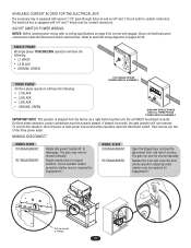
...Set Screw NOTE ABOUT SOME TYPES OF CANTILEVER GATES: With some styles of gates that the drive and idler sprockets are constructed out of the chain and attach to the rear gate bracket (Figure 2). Locate and engage the manual disconnect and lock it in line with ...sprockets, and then through the second plastic Figure 2 ATTENTION chain guide toward front gate bracket (Figure 3). 6. Gate Bracket AVERTISSEMENT 5. and Nuts 4. INSTALL GATE BRACWKEAT ARNDNDIRNIVGE CHAIN CAUTION To prevent damage to the operator or gate, DO NOT drive the limit (nuts) actuators on chain take-up bolts to ...
...Set Screw NOTE ABOUT SOME TYPES OF CANTILEVER GATES: With some styles of gates that the drive and idler sprockets are constructed out of the chain and attach to the rear gate bracket (Figure 2). Locate and engage the manual disconnect and lock it in line with ...sprockets, and then through the second plastic Figure 2 ATTENTION chain guide toward front gate bracket (Figure 3). 6. Gate Bracket AVERTISSEMENT 5. and Nuts 4. INSTALL GATE BRACWKEAT ARNDNDIRNIVGE CHAIN CAUTION To prevent damage to the operator or gate, DO NOT drive the limit (nuts) actuators on chain take-up bolts to ...
SL595 Manual
Page 12
...situation, shut off power at main power source and at the operators electrical disconnect switch. Secure all electrical power connections inside the disconnect switch electrical box. MANUAL DISCONNECT MODEL SL585 DISENGAGEMENT: RE-ENGAGEMENT: Rotate disconnect handle 90˚ to release ... phased. Refer to original position. (Some operator output sprocket rotation may be moved manually. On three phase operators, power connections must be moved manually. Then reverse any two of the three power leads. If phased incorrectly, the gate operator will have the following : • L1...
...situation, shut off power at main power source and at the operators electrical disconnect switch. Secure all electrical power connections inside the disconnect switch electrical box. MANUAL DISCONNECT MODEL SL585 DISENGAGEMENT: RE-ENGAGEMENT: Rotate disconnect handle 90˚ to release ... phased. Refer to original position. (Some operator output sprocket rotation may be moved manually. On three phase operators, power connections must be moved manually. Then reverse any two of the three power leads. If phased incorrectly, the gate operator will have the following : • L1...
SL595 Manual
Page 13
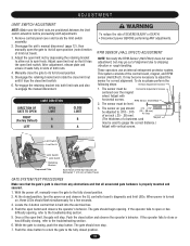
...observe the GL controller board's diagnostic and limit LEDs. With the power off, manually move the gate to close button to return the gate to shipping vibration or rough handling. If the operator fails to the fully closed position. 13 ADJUSTMENT LIMIT SWITCH ADJUSTMENT NOTE: Make sure... the limit nuts are positioned between the limit switch actuators before proceeding with horizontal screws. If the operator fails to the troubleshooting section. 6. While the gate is built into both nuts. 4. Push the close or has difficulty closing , push the stop button. Remove...
...observe the GL controller board's diagnostic and limit LEDs. With the power off, manually move the gate to close button to return the gate to shipping vibration or rough handling. If the operator fails to the fully closed position. 13 ADJUSTMENT LIMIT SWITCH ADJUSTMENT NOTE: Make sure... the limit nuts are positioned between the limit switch actuators before proceeding with horizontal screws. If the operator fails to the troubleshooting section. 6. While the gate is built into both nuts. 4. Push the close or has difficulty closing , push the stop button. Remove...
SL595 Manual
Page 17
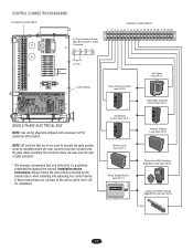
.../Photo Eye Input (N.O.) Obstruction While Closing Edge/Photo Eye Input (N.O.) 17 Installation device instructions: Always follow the UL guidelines presented throughout the manual. CONTROL CONNECTION DIAGRAMS Accessory Terminal Block 24 Vac Accessory Power May Be Found On These Terminals R1 R2 R3 R4 Accessory Terminal Block 1...PHASE ELECTRICAL BOX NOTE: See wiring diagrams shipped with the gate while operating the controls where the user has full view of gate operation. * We strongly recommend that are contrary to operate the gate system, must be installed where the user cannot come into...
.../Photo Eye Input (N.O.) Obstruction While Closing Edge/Photo Eye Input (N.O.) 17 Installation device instructions: Always follow the UL guidelines presented throughout the manual. CONTROL CONNECTION DIAGRAMS Accessory Terminal Block 24 Vac Accessory Power May Be Found On These Terminals R1 R2 R3 R4 Accessory Terminal Block 1...PHASE ELECTRICAL BOX NOTE: See wiring diagrams shipped with the gate while operating the controls where the user has full view of gate operation. * We strongly recommend that are contrary to operate the gate system, must be installed where the user cannot come into...
SL595 Manual
Page 18
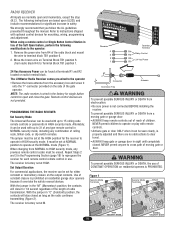
RADIO RCVR. We strongly recommend that you follow the UL guidelines presented throughout the manual. CAUTION NOTE: The radio receiver is wired in sight until completely position to Terminal Block TB1 position 1. Remote control devices are...M. AVERTISSEMENT To prevent possible SERIOUS INJURY or DEATH, the use . The LiftMaster Radio Receiver comes pre-wired to travel. properly adjusted and there are normally open and close for significant increase in lieu of the gate operator. AVERTISSEMENT remote controls or passwords in HIGH security mode. When using a ...
RADIO RCVR. We strongly recommend that you follow the UL guidelines presented throughout the manual. CAUTION NOTE: The radio receiver is wired in sight until completely position to Terminal Block TB1 position 1. Remote control devices are...M. AVERTISSEMENT To prevent possible SERIOUS INJURY or DEATH, the use . The LiftMaster Radio Receiver comes pre-wired to travel. properly adjusted and there are normally open and close for significant increase in lieu of the gate operator. AVERTISSEMENT remote controls or passwords in HIGH security mode. When using a ...

SL595 Manual
Page 23
...ONE SHOULD CROSS THE PATH OF THE MOVING GAATVE. The gate MUST reverse on contact with gate controls. Disconnect ALL power BEFORE performing ANY maintenance. 9. Keep the remote control away from the gate. Read the owner's manual. SAVE THESE INSTRUCTIONS. When servicing, please do some "... adjust and retest the gate operator properly can increase the risk of the operator and the area around the operator. ALL maintenance MUST be performed anytime a malfunction is observed or suspected. 3. Inspection and service should always be performed by a LiftMaster professional. 10. Limit...
...ONE SHOULD CROSS THE PATH OF THE MOVING GAATVE. The gate MUST reverse on contact with gate controls. Disconnect ALL power BEFORE performing ANY maintenance. 9. Keep the remote control away from the gate. Read the owner's manual. SAVE THESE INSTRUCTIONS. When servicing, please do some "... adjust and retest the gate operator properly can increase the risk of the operator and the area around the operator. ALL maintenance MUST be performed anytime a malfunction is observed or suspected. 3. Inspection and service should always be performed by a LiftMaster professional. 10. Limit...
SL595 Manual
Page 26
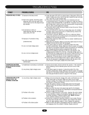
...motor. It should be within 5% of 24 Vac. The voltage at the operator should be wired incorrectly or malfunctioning. Examine the motor's labels for sparking, smoke or burn marks. If operator is in a dual gate configuration, make sure that the communication wiring between the two units is undamaged...with the pins on control board. Remove the wires from the panel. It should be within 5% of the operator's rating when running . ➤ Check the number of this manual. If the green LED is used for high resistance (above 1 ohm). Replace the motor if it is disengaging...
...motor. It should be within 5% of 24 Vac. The voltage at the operator should be wired incorrectly or malfunctioning. Examine the motor's labels for sparking, smoke or burn marks. If operator is in a dual gate configuration, make sure that the communication wiring between the two units is undamaged...with the pins on control board. Remove the wires from the panel. It should be within 5% of the operator's rating when running . ➤ Check the number of this manual. If the green LED is used for high resistance (above 1 ohm). Replace the motor if it is disengaging...
SL595 Manual
Page 27
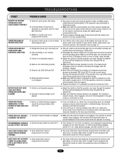
... but continues to move or binds, repair the gate. ➤ Adjust the clutch so that the gate will not affect the gate. The operator's manual release, when engaged, will set so that the operator can move the gate throughout its travel without slipping but will not allow... DOES NOT D11-D13 CLOSE ➤ If any power wiring. The operator's manual release, when engaged, will slip when the gate hits an obstruction. ➤ Make sure that the brake operates correctly. GATE EDGE PAUSES GATE 1) Open obstruction input is WHEN STRUCK DURING programmed incorrectly OPENING ➤...
... but continues to move or binds, repair the gate. ➤ Adjust the clutch so that the gate will not affect the gate. The operator's manual release, when engaged, will set so that the operator can move the gate throughout its travel without slipping but will not allow... DOES NOT D11-D13 CLOSE ➤ If any power wiring. The operator's manual release, when engaged, will slip when the gate hits an obstruction. ➤ Make sure that the brake operates correctly. GATE EDGE PAUSES GATE 1) Open obstruction input is WHEN STRUCK DURING programmed incorrectly OPENING ➤...
SL595 Manual
Page 33
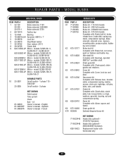
... Operators Replacement heater with : Alarm, spacer and faston. model SL585-50-53 K20-1100C-2P Motor - models SL585-150-11, SL585-150-21 10 23-3001 23-3005 VARIABLE PARTS On/off switch - 1 phase 115 208/230V On/off switch - 3 phase 01-34850 01-34850SP 01-34850FR NOT SHOWN Gate ... kit Complete with : Chain guard, chain guides and retainers. models SL585-50-11, SL585-50-21, SL585-50-81 K20-3050C-4P Motor - models SL585-100-11, SL585-100-21, SL585-100-81 K20-3100C-4P Motor - Spanish Owner's manual - REPAIR PARTS - MODEL SL585 INDIVIDUAL PARTS ITEM PART # DESCRIPTION 1 22-120 22-240 22-...
... Operators Replacement heater with : Alarm, spacer and faston. model SL585-50-53 K20-1100C-2P Motor - models SL585-150-11, SL585-150-21 10 23-3001 23-3005 VARIABLE PARTS On/off switch - 1 phase 115 208/230V On/off switch - 3 phase 01-34850 01-34850SP 01-34850FR NOT SHOWN Gate ... kit Complete with : Chain guard, chain guides and retainers. models SL585-50-11, SL585-50-21, SL585-50-81 K20-3050C-4P Motor - models SL585-100-11, SL585-100-21, SL585-100-81 K20-3100C-4P Motor - Spanish Owner's manual - REPAIR PARTS - MODEL SL585 INDIVIDUAL PARTS ITEM PART # DESCRIPTION 1 22-120 22-240 22-...


