RSL12U Installation Manual
Page 1
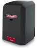
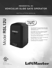
LiftMaster 845 Larch Avenue Elmhurst, IL 60126-1196 Model RSL12U RESIDENTIAL DC VEHICULAR SLIDE GATE OPERATOR INSTALLATION MANUAL • THIS PRODUCT IS TO BE INSTALLED AND SERVICED BY A TRAINED GATE SYSTEMS TECHNICIAN ONLY. • This model is for use on vehicular passage ... intended for use on pedestrian passage gates. • This model is intended for use in Class I and II vehicular slide gate applications. • Visit LiftMaster.com to locate a professional installing dealer in your area. • This gate operator is compatible with MyQ® and Security+ 2.0® accessories.
LiftMaster 845 Larch Avenue Elmhurst, IL 60126-1196 Model RSL12U RESIDENTIAL DC VEHICULAR SLIDE GATE OPERATOR INSTALLATION MANUAL • THIS PRODUCT IS TO BE INSTALLED AND SERVICED BY A TRAINED GATE SYSTEMS TECHNICIAN ONLY. • This model is for use on vehicular passage ... intended for use on pedestrian passage gates. • This model is intended for use in Class I and II vehicular slide gate applications. • Visit LiftMaster.com to locate a professional installing dealer in your area. • This gate operator is compatible with MyQ® and Security+ 2.0® accessories.

RSL12U Installation Manual
Page 2
...INSTALL THE COVER 20 ADJUSTMENT 21 LIMIT AND FORCE ADJUSTMENT 21 OBSTRUCTION TEST 22 PROGRAMMING 23 REMOTE CONTROLS (NOT PROVIDED 23 LIFTMASTER INTERNET GATEWAY (NOT PROVIDED 24 ERASE ALL CODES 24 ERASE LIMITS 24 TO REMOVE AND ERASE MONITORED ENTRAPMENT PROTECTION DEVICES 24... OPERATION 25 CONTROL BOARD OVERVIEW 25 RESET SWITCH 26 MANUAL DISCONNECT 26 OPERATOR ALARM 26 REMOTE CONTROL 26 ACCESSORY WIRING 27 EXTERNAL CONTROL DEVICES 27 LOCKS 28 MISCELLANEOUS WIRING 28 ...
...INSTALL THE COVER 20 ADJUSTMENT 21 LIMIT AND FORCE ADJUSTMENT 21 OBSTRUCTION TEST 22 PROGRAMMING 23 REMOTE CONTROLS (NOT PROVIDED 23 LIFTMASTER INTERNET GATEWAY (NOT PROVIDED 24 ERASE ALL CODES 24 ERASE LIMITS 24 TO REMOVE AND ERASE MONITORED ENTRAPMENT PROTECTION DEVICES 24... OPERATION 25 CONTROL BOARD OVERVIEW 25 RESET SWITCH 26 MANUAL DISCONNECT 26 OPERATOR ALARM 26 REMOTE CONTROL 26 ACCESSORY WIRING 27 EXTERNAL CONTROL DEVICES 27 LOCKS 28 MISCELLANEOUS WIRING 28 ...

RSL12U Installation Manual
Page 3
... GATES PROPERLY MAINTAINED. Failure to adjust and retest the gate operator properly can increase the risk of travel, retest the gate operator. Read the owner's manual. SAFETY USAGE CLASS CLASS I - RESIDENTIAL VEHICULAR GATE OPERATOR A vehicular gate operator (or system) intended for both entrapment protection means.
... GATES PROPERLY MAINTAINED. Failure to adjust and retest the gate operator properly can increase the risk of travel, retest the gate operator. Read the owner's manual. SAFETY USAGE CLASS CLASS I - RESIDENTIAL VEHICULAR GATE OPERATOR A vehicular gate operator (or system) intended for both entrapment protection means.

RSL12U Installation Manual
Page 4
... and where the user is greater than 6 inches (152 mm) above the ground to potential hazards. 3. For a gate operator utilizing a non-contact sensor: a. Reference owner's manual regarding placement of non-contact sensor for the construction and the usage class of entrapment. One or more contact sensors shall be installed, one component...
... and where the user is greater than 6 inches (152 mm) above the ground to potential hazards. 3. For a gate operator utilizing a non-contact sensor: a. Reference owner's manual regarding placement of non-contact sensor for the construction and the usage class of entrapment. One or more contact sensors shall be installed, one component...

RSL12U Installation Manual
Page 5
... 8 feet (2.44 m) above grade and for barbed wire shall not be less than 6 feet (1.83 m) above grade. 1.5 An existing gate latch shall be disabled when a manually operated gate is in either the fully open position or the fully closed positions. These stops shall be installed at either the top of the...
... 8 feet (2.44 m) above grade and for barbed wire shall not be less than 6 feet (1.83 m) above grade. 1.5 An existing gate latch shall be disabled when a manually operated gate is in either the fully open position or the fully closed positions. These stops shall be installed at either the top of the...

RSL12U Installation Manual
Page 13
... in this position. 4. Connect the chain to the ground. Chain should not be level with the top idler pulley and parallel to the ground. Manually close the gate and align the bottom bracket so the chain will be level with the idler pulley and parallel to the brackets using the...of sag for every 10 feet of chain length. 12 Front Bracket Idler Pulley MUST have excessive slack. Weld the front bracket in this position. 2. Manually open the gate and line up the rear bracket so the chain will require two extra idler pulleys. Route the chain through the operator. 4. NOTE...
... in this position. 4. Connect the chain to the ground. Chain should not be level with the top idler pulley and parallel to the ground. Manually close the gate and align the bottom bracket so the chain will be level with the idler pulley and parallel to the brackets using the...of sag for every 10 feet of chain length. 12 Front Bracket Idler Pulley MUST have excessive slack. Weld the front bracket in this position. 2. Manually open the gate and line up the rear bracket so the chain will require two extra idler pulleys. Route the chain through the operator. 4. NOTE...

RSL12U Installation Manual
Page 15
... sensor entrapment protection for monitored devices, which include pulsed photoelectric sensors, resistive edge sensors, and pulsed edge sensors. Refer to the specific entrapment protection device manual for wiring the entrapment protection devices depending on the switch settings (located next to the terminals) Switch set to CLOSE: gate reverses fully when obstruction...
... sensor entrapment protection for monitored devices, which include pulsed photoelectric sensors, resistive edge sensors, and pulsed edge sensors. Refer to the specific entrapment protection device manual for wiring the entrapment protection devices depending on the switch settings (located next to the terminals) Switch set to CLOSE: gate reverses fully when obstruction...
RSL12U Installation Manual
Page 26
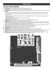
...closed if there is restored or battery voltage increases. • Option select switch set to the OFF position, then the gate will display as RSL12U. Set to SECURE makes the gate difficult to OFF. See Adjust Limits section. 2 SET CLOSE Button: The SET CLOSE button sets the CLOSE...is in the Troubleshooting section. 11 DIAGNOSTICS Display: The diagnostics code display will show after the operator type, example "1.2". 12 BACKDRIVE Switch: Set to MANUAL will allow the gate to be set to OPEN forces gate to the desired setting. See Adjust Limits section. 4 BATT FAIL: • When...
...closed if there is restored or battery voltage increases. • Option select switch set to the OFF position, then the gate will display as RSL12U. Set to SECURE makes the gate difficult to OFF. See Adjust Limits section. 2 SET CLOSE Button: The SET CLOSE button sets the CLOSE...is in the Troubleshooting section. 11 DIAGNOSTICS Display: The diagnostics code display will show after the operator type, example "1.2". 12 BACKDRIVE Switch: Set to MANUAL will allow the gate to be set to OPEN forces gate to the desired setting. See Adjust Limits section. 4 BATT FAIL: • When...

RSL12U Installation Manual
Page 27
...operator is low. OPERATION RESET SWITCH The reset switch is located on the gate's track such as follows: When gate is in the closed manually. The operator does not need to shut off the gate rail. OPERATOR ALARM If a contact sensor detects an obstruction twice consecutively the alarm will...need to be reset: A. The gate is given after doing this. Debris is in the present position and will need to NORMAL OPERATION. MANUAL DISCONNECT Press the reset switch to RESET/DISCONNECT to allow the gate to be opened and closed position, activation of the remote control will close...
...operator is low. OPERATION RESET SWITCH The reset switch is located on the gate's track such as follows: When gate is in the closed manually. The operator does not need to shut off the gate rail. OPERATOR ALARM If a contact sensor detects an obstruction twice consecutively the alarm will...need to be reset: A. The gate is given after doing this. Debris is in the present position and will need to NORMAL OPERATION. MANUAL DISCONNECT Press the reset switch to RESET/DISCONNECT to allow the gate to be opened and closed position, activation of the remote control will close...

RSL12U Installation Manual
Page 30
...NEVER let children operate or play with national and local electrical codes. Read the owner's manual. ALWAYS disconnect the batteries to the operator or in accordance with gate controls. Use only LiftMaster part 29-NP712 for vehicles ONLY. To tighten the drive chain adjust either of sag... cold temperatures. Upon completion of maintenance the area MUST be cleared and secured, at that time the unit may be performed by a LiftMaster professional. • Activate gate ONLY when it can increase the risk of properly. Have a qualified service person make repairs to gate hardware...
...NEVER let children operate or play with national and local electrical codes. Read the owner's manual. ALWAYS disconnect the batteries to the operator or in accordance with gate controls. Use only LiftMaster part 29-NP712 for vehicles ONLY. To tighten the drive chain adjust either of sag... cold temperatures. Upon completion of maintenance the area MUST be cleared and secured, at that time the unit may be performed by a LiftMaster professional. • Activate gate ONLY when it can increase the risk of properly. Have a qualified service person make repairs to gate hardware...

RSL12U Installation Manual
Page 35
...input LEDs a) Check all vehicle detector inputs for an active detector b) Check if AC power is too difficult to move a) Use manual disconnect, manually move to a limit position b) Gate is available. b) Check Stop button is too difficult to move easily and freely through its entire... is stuck b) Stop button active or jumper not in place for a "stuck on" detector Operator does not respond to limit. a) Use manual disconnect, manually move easily and freely through its entire range, limit to a wireless control or transmitter a) Check XMITTER LED when wireless control is active b)...
...input LEDs a) Check all vehicle detector inputs for an active detector b) Check if AC power is too difficult to move a) Use manual disconnect, manually move to a limit position b) Gate is available. b) Check Stop button is too difficult to move easily and freely through its entire... is stuck b) Stop button active or jumper not in place for a "stuck on" detector Operator does not respond to limit. a) Use manual disconnect, manually move easily and freely through its entire range, limit to a wireless control or transmitter a) Check XMITTER LED when wireless control is active b)...
RSL12U Wiring Diagram Manual
Page 1
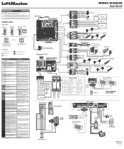
... Edge Sensor for obstruction. Replace APE assembly. 99 Normal Operation No action required COAXIAL CABLE ANTENNA Control Board CONTROLS WIRING DIAGRAM Model RSL12U Jumper N.C. If so, erase limits, enter limit setup mode and set too tightly against a nonresilient hard stop (re-adjust limit... wiring on a 24V system. 43 Exit Loop Error 44 Shadow Loop Error 45 Interrupt Loop Error Failure or missing loop (SHORT or OPEN LiftMaster Plug-in the manual. 93 RPM / STALL Reversal (Operator 1) RPM / STALL Reversal (Operator 2) 94 Check for power. Maglock (Optional) (not provided) ...
... Edge Sensor for obstruction. Replace APE assembly. 99 Normal Operation No action required COAXIAL CABLE ANTENNA Control Board CONTROLS WIRING DIAGRAM Model RSL12U Jumper N.C. If so, erase limits, enter limit setup mode and set too tightly against a nonresilient hard stop (re-adjust limit... wiring on a 24V system. 43 Exit Loop Error 44 Shadow Loop Error 45 Interrupt Loop Error Failure or missing loop (SHORT or OPEN LiftMaster Plug-in the manual. 93 RPM / STALL Reversal (Operator 1) RPM / STALL Reversal (Operator 2) 94 Check for power. Maglock (Optional) (not provided) ...

RSL12U Quick Start Guide Manual
Page 1
Refer to the concrete pad. Minimum of LiftMaster external monitored entrapment protection devices. Attach the chain to the front gate 8 bracket. 3 Attach the operator to the installation manual for concrete pad. 1/2" (1.8 cm) 1" - 2" (2.5 - 5.1 cm) (conduit location) INSTALLATION 4 Attach the front gate ...This QuickStart is installed and operated properly. All Rights Reserved 6" (15.2 cm) Above Ground Below the frost line. Model RSL12U 24" (61 cm) QuickStart for single gate application 1 Determine location for complete information regarding installation, testing, and programming. ...
Refer to the concrete pad. Minimum of LiftMaster external monitored entrapment protection devices. Attach the chain to the front gate 8 bracket. 3 Attach the operator to the installation manual for concrete pad. 1/2" (1.8 cm) 1" - 2" (2.5 - 5.1 cm) (conduit location) INSTALLATION 4 Attach the front gate ...This QuickStart is installed and operated properly. All Rights Reserved 6" (15.2 cm) Above Ground Below the frost line. Model RSL12U 24" (61 cm) QuickStart for single gate application 1 Determine location for complete information regarding installation, testing, and programming. ...
RSL12U Quick Start Guide Manual
Page 2
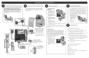
... 12V SOLAR PANEL (OPTIONAL) 10W minimum - 30W maximum, wired in place when using the MAX transmitter Timer-to your manual for complete wiring information. Run the gate in transformer (see images below). Make sure the antenna is stopping at times without... AND ADJUSTMENTS Install Monitored Entrapment Protection Device This operator contains an inherent (internal) entrapment protection system and REQUIRES the addition of a LiftMaster external monitored entrapment protection system (non-contact photoelectric sensor or contact edge sensor) for EACH entrapment zone prior to less than 11...
... 12V SOLAR PANEL (OPTIONAL) 10W minimum - 30W maximum, wired in place when using the MAX transmitter Timer-to your manual for complete wiring information. Run the gate in transformer (see images below). Make sure the antenna is stopping at times without... AND ADJUSTMENTS Install Monitored Entrapment Protection Device This operator contains an inherent (internal) entrapment protection system and REQUIRES the addition of a LiftMaster external monitored entrapment protection system (non-contact photoelectric sensor or contact edge sensor) for EACH entrapment zone prior to less than 11...

RSL12U Troubleshooting Guide Manual
Page 2
... 20 MODELS SL585U AND SL595U (THREE PHASE 21 MODEL LA412U 22 MODEL LA400U 23 MODEL LA500U 24 MODELS CSL24U AND CSW24U 25 MODELS RSL12U AND RSW12U 26 MYQ® 27 FREQUENTLY ASKED QUESTIONS 27 TROUBLESHOOTING MyQ® ...29 MyQ® ACCOUNT ISSUES 30 MyQ® ACCOUNT...from electric shock. IMPORTANT NOTE: • BEFORE attempting to install, operate or maintain the operator, you must read and fully understand the manual provided with the warnings that accompany it will alert you to your operator and follow all safety instructions. • DO NOT attempt repair ...
... 20 MODELS SL585U AND SL595U (THREE PHASE 21 MODEL LA412U 22 MODEL LA400U 23 MODEL LA500U 24 MODELS CSL24U AND CSW24U 25 MODELS RSL12U AND RSW12U 26 MYQ® 27 FREQUENTLY ASKED QUESTIONS 27 TROUBLESHOOTING MyQ® ...29 MyQ® ACCOUNT ISSUES 30 MyQ® ACCOUNT...from electric shock. IMPORTANT NOTE: • BEFORE attempting to install, operate or maintain the operator, you must read and fully understand the manual provided with the warnings that accompany it will alert you to your operator and follow all safety instructions. • DO NOT attempt repair ...

RSL12U Troubleshooting Guide Manual
Page 17
Use LiftMaster low current draw accessories. • Check that the number of gate cycles does not exceed the cycle ratings for solar application 3 ZONE 3 (2 Hours of Sunlight/... solar panel is facing south within 150 feet of three 10W 12V panels. 24V operators require two 10W 12V panels up to your gate operator manual for the application. • Check that the whole panel(s) is not charging the battery.
Use LiftMaster low current draw accessories. • Check that the number of gate cycles does not exceed the cycle ratings for solar application 3 ZONE 3 (2 Hours of Sunlight/... solar panel is facing south within 150 feet of three 10W 12V panels. 24V operators require two 10W 12V panels up to your gate operator manual for the application. • Check that the whole panel(s) is not charging the battery.

RSL12U Troubleshooting Guide Manual
Page 30
... an Internet Gateway will not successfully connect to the Internet: • An incompatible router • A router configuration setting (e.g. Go to LiftMaster.com/MyQ-PAS and look for 30 seconds. Disconnect and reconnect power to the Internet Gateway. SonicWALL®, ZyWall) is installed. •...180 seconds or greater. SOLUTION Determine if a router setting (e.g. MAC address filtering, firewall settings). • Review the router's settings and manual. • Router must be adjusted to be set to DHCP to provide an IP address to the Internet Gateway. • The ...
... an Internet Gateway will not successfully connect to the Internet: • An incompatible router • A router configuration setting (e.g. Go to LiftMaster.com/MyQ-PAS and look for 30 seconds. Disconnect and reconnect power to the Internet Gateway. SonicWALL®, ZyWall) is installed. •...180 seconds or greater. SOLUTION Determine if a router setting (e.g. MAC address filtering, firewall settings). • Review the router's settings and manual. • Router must be adjusted to be set to DHCP to provide an IP address to the Internet Gateway. • The ...

RSL12U Troubleshooting Guide Manual
Page 31
... blue LED will be solid on the MyQ app when attempting to add a device, verify the MyQ device is not already associated with the installation manual, user guide and quick start guide. • MyQ-Enabled devices communicate using a longer CAT5 cable or higher quality Ethernet cable (up to an Internet Gateway...
... blue LED will be solid on the MyQ app when attempting to add a device, verify the MyQ device is not already associated with the installation manual, user guide and quick start guide. • MyQ-Enabled devices communicate using a longer CAT5 cable or higher quality Ethernet cable (up to an Internet Gateway...

RSL12U Troubleshooting Guide Manual
Page 34
... try again. • Log out of the account. The Internet Gateway will not be replaced or serviced. • Contact a local dealer or LiftMaster Technical Service Center at 800.528.2806. Add the device back to another account. Device is already registered to the account. account and unable to... 33 Log back into the account. If you have access to the other account, you do not have connected with power. • Operate device manually. • If the device responds, remove the device from the account before it to register. • The device must be removed from the ...
... try again. • Log out of the account. The Internet Gateway will not be replaced or serviced. • Contact a local dealer or LiftMaster Technical Service Center at 800.528.2806. Add the device back to another account. Device is already registered to the account. account and unable to... 33 Log back into the account. If you have access to the other account, you do not have connected with power. • Operate device manually. • If the device responds, remove the device from the account before it to register. • The device must be removed from the ...
RSL12U Troubleshooting Guide Manual
Page 35
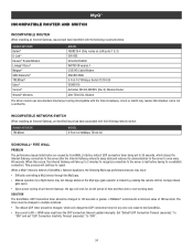
...following MyQ app performance issues may not change the UDP connection timer for a brief period of time and then enter a non-working state. LiftMaster® recommends a minimum value of 180 seconds. The timer must have been identified with the Internet Gateway. When a MyQ® device ...MyQ® INCOMPATIBLE ROUTER AND SWITCH INCOMPATIBLE ROUTER When installing an Internet Gateway, issues have the UDP connection timeout updated manually. When this situation, but is closed by a MyQ device may occur: • Difficulty controlling a MyQ device through the MyQ app. &#...
...following MyQ app performance issues may not change the UDP connection timer for a brief period of time and then enter a non-working state. LiftMaster® recommends a minimum value of 180 seconds. The timer must have been identified with the Internet Gateway. When a MyQ® device ...MyQ® INCOMPATIBLE ROUTER AND SWITCH INCOMPATIBLE ROUTER When installing an Internet Gateway, issues have the UDP connection timeout updated manually. When this situation, but is closed by a MyQ device may occur: • Difficulty controlling a MyQ device through the MyQ app. &#...


