
PASSPORT Manual
Page 1
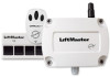
ACCESS CONTROL COMPATIBILITY The CPWR outputs a 26-bit or 30-bit Wiegand format compatible with remote control transmitters. • Activate gate or door ONLY when it can be seen clearly, is properly adjusted, and there are no obstructions to door travel. ... or DEATH from a moving gate or door. 1 MODEL CPWR 390 MHz Wiegand Receiver with Passport Technology SPECIFICATIONS Power: 12VDC, 50 mA Temperature Rating: -40° to +185° F Model CPWR3 RF Frequency: 390 MHZ Accessory Transmitters Visors: CPT1, CPT2, CPT3, CPT4 Key chains: CPTK1, CPTK3, CPTK1PH, CPTK3PH OVERVIEW The...
ACCESS CONTROL COMPATIBILITY The CPWR outputs a 26-bit or 30-bit Wiegand format compatible with remote control transmitters. • Activate gate or door ONLY when it can be seen clearly, is properly adjusted, and there are no obstructions to door travel. ... or DEATH from a moving gate or door. 1 MODEL CPWR 390 MHz Wiegand Receiver with Passport Technology SPECIFICATIONS Power: 12VDC, 50 mA Temperature Rating: -40° to +185° F Model CPWR3 RF Frequency: 390 MHZ Accessory Transmitters Visors: CPT1, CPT2, CPT3, CPT4 Key chains: CPTK1, CPTK3, CPTK1PH, CPTK3PH OVERVIEW The...

PASSPORT Manual
Page 2
... Switch Setting S1 FORMAT 3 2 1 0 BUTTON 3 2 1 FFC 3 1 2 Buttons 1-3 are factory-set to ON. 3-Button Remote Transmitter 1535F11 CPT4 Transmitter 1535F8 S1 FORMAT 3 2 1 0 3 BUTTON 2 1 FFC Buttons 1-3 are three DIP switches used to set to the LEFT. Turn screws... counterclockwise 1/4 turn and remove front cover. 3. Figure 4: CPT4 Transmitter Button Switches Figure 5: 3-Button Transmitter Button Switches 2 Disconnect power to Figure 3. 30-bit Switch Settings (Default): S1, 3 = OFF or 0 S1, 2 = OFF...
... Switch Setting S1 FORMAT 3 2 1 0 BUTTON 3 2 1 FFC 3 1 2 Buttons 1-3 are factory-set to ON. 3-Button Remote Transmitter 1535F11 CPT4 Transmitter 1535F8 S1 FORMAT 3 2 1 0 3 BUTTON 2 1 FFC Buttons 1-3 are three DIP switches used to set to the LEFT. Turn screws... counterclockwise 1/4 turn and remove front cover. 3. Figure 4: CPT4 Transmitter Button Switches Figure 5: 3-Button Transmitter Button Switches 2 Disconnect power to Figure 3. 30-bit Switch Settings (Default): S1, 3 = OFF or 0 S1, 2 = OFF...

PASSPORT Manual
Page 3
NOTE: For installations that require the facility code of the transmitters to be installed at the factory to left). FACILITY CODE 15 7 3 14 6 13 5 12 4 11 3 10 2 9 1 8 0 FORMAT 2 1 0 3 BUTTON 2 1 FFC Facility code switches 6-15 are set ... using an extension kit, do not allow it to the access control system's instructions for assistance. Facility codes are not used (must be in the transmitter at least 5' apart to avoid "cross-talk". Facility Code Factory Setting = All OFF (switches set in the ON position (switch set to the access control...
NOTE: For installations that require the facility code of the transmitters to be installed at the factory to left). FACILITY CODE 15 7 3 14 6 13 5 12 4 11 3 10 2 9 1 8 0 FORMAT 2 1 0 3 BUTTON 2 1 FFC Facility code switches 6-15 are set ... using an extension kit, do not allow it to the access control system's instructions for assistance. Facility codes are not used (must be in the transmitter at least 5' apart to avoid "cross-talk". Facility Code Factory Setting = All OFF (switches set in the ON position (switch set to the access control...

PASSPORT Manual
Page 4
... (refer to arcing power lines. 2. DATA - Check the power. The SIGNAL LED (Figure 9) should be within view of the transmitter's signal is operating. 3. Ensure that the receiver recognizes the transmission data as coming from other sources. NOTE: It may be strong RF... interference from a Chamberlain® transmitter with Passport technology. TESTING AND TROUBLESHOOTING 1. Press the transmitter button previously set in step 4, page 3, within the range of receiver by having an electrician wire a ...
... (refer to arcing power lines. 2. DATA - Check the power. The SIGNAL LED (Figure 9) should be within view of the transmitter's signal is operating. 3. Ensure that the receiver recognizes the transmission data as coming from other sources. NOTE: It may be strong RF... interference from a Chamberlain® transmitter with Passport technology. TESTING AND TROUBLESHOOTING 1. Press the transmitter button previously set in step 4, page 3, within the range of receiver by having an electrician wire a ...
