
PASSPORT Manual
Page 1
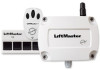
... in Chamberlain® rolling code technology. NEVER permit anyone to an access control unit such as a Sentex Telephone Entry System. MODEL CPWR 390 MHz Wiegand Receiver with Passport Technology SPECIFICATIONS Power: 12VDC, 50 mA Temperature Rating: -40° to +185° F Model CPWR3 RF Frequency: 390 MHZ Accessory Transmitters Visors: CPT1, CPT2...
... in Chamberlain® rolling code technology. NEVER permit anyone to an access control unit such as a Sentex Telephone Entry System. MODEL CPWR 390 MHz Wiegand Receiver with Passport Technology SPECIFICATIONS Power: 12VDC, 50 mA Temperature Rating: -40° to +185° F Model CPWR3 RF Frequency: 390 MHZ Accessory Transmitters Visors: CPT1, CPT2...

PASSPORT Manual
Page 2
... Switches 2 Before or while touching the circuit board, discharge any of the DIP switches (Figure 1), power MUST be disconnected from the receiver (unplug the terminal block from J2 on the DIP switch itself). 1. The output code format switch settings are three DIP switches used ...(Figure 2). Set the transmitter button response(s). • There are factory-set the transmitter button response(s) (Figures 4 or 5). • To disallow receiver response to transmitter buttons, move the DIP switch(es) to ON. To change the settings to 26-bit, refer to Button #1 settings, but ...
... Switches 2 Before or while touching the circuit board, discharge any of the DIP switches (Figure 1), power MUST be disconnected from the receiver (unplug the terminal block from J2 on the DIP switch itself). 1. The output code format switch settings are three DIP switches used ...(Figure 2). Set the transmitter button response(s). • There are factory-set the transmitter button response(s) (Figures 4 or 5). • To disallow receiver response to transmitter buttons, move the DIP switch(es) to ON. To change the settings to 26-bit, refer to Button #1 settings, but ...

PASSPORT Manual
Page 3
... (Figure 7). 3. Connect the antenna. FFC Factory Setting = ON (switch set switch to avoid code duplication. INSTALLATION AND WIRING 1. The receivers should be in the Appendix on antenna clockwise and slide rubber boot down to right). Screw on page 5 for assistance. Refer to surface ... POWER GRANTED D16 SENTEX SYSTEMS MADE I N USA Mounting Holes J2 To Access Control Circuit Board (Reader Port) Figure 8 3 Mount receiver to the access control system's instructions for the antenna. The outside of LED flash sequences (this is not ground. Facility codes are ...
... (Figure 7). 3. Connect the antenna. FFC Factory Setting = ON (switch set switch to avoid code duplication. INSTALLATION AND WIRING 1. The receivers should be in the Appendix on antenna clockwise and slide rubber boot down to right). Screw on page 5 for assistance. Refer to surface ... POWER GRANTED D16 SENTEX SYSTEMS MADE I N USA Mounting Holes J2 To Access Control Circuit Board (Reader Port) Figure 8 3 Mount receiver to the access control system's instructions for the antenna. The outside of LED flash sequences (this is not ground. Facility codes are ...

PASSPORT Manual
Page 4
... Interference due to flicker continuously while the receiver is lit (Figure 9). GRANTED - Do not over tighten. The SIGNAL LED (Figure 9) should be strong RF interference from a Chamberlain® transmitter with Passport technology. Common sources of receiver by having an electrician wire a noise ...suppressor into the lamp, light, or sign circuit. DATA - Green This LED indicates that the receiver has power. D11 SIGNAL D12 DATA D13 ...
... Interference due to flicker continuously while the receiver is lit (Figure 9). GRANTED - Do not over tighten. The SIGNAL LED (Figure 9) should be strong RF interference from a Chamberlain® transmitter with Passport technology. Common sources of receiver by having an electrician wire a noise ...suppressor into the lamp, light, or sign circuit. DATA - Green This LED indicates that the receiver has power. D11 SIGNAL D12 DATA D13 ...

PASSPORT Manual
Page 5
... 049 050 051 052 053 054 055 056 057 058 059 060 061 062 063 51 1 1 1 1 1 1 1 1 1 1 1 1 1 1 1 41 1 1 1 1 1 1 1 1 1 1 1 1 1 1 1 30 0 0 0 0 0 0 0 1 1 1 1 1 1 1 1 20 0 0 0 1 1 1 1 0 0 0 0 1 1 1 1 10 0 1 1 0 0 1 1 0 0 1 1 0 0 1 1 00 1 0 1 0 1 0 1 0 1 0 1 0 1 0 1 5 Also, when setting the receiver's DIP switches, refer only to Figure 1 on the DIP switch itself).
... 049 050 051 052 053 054 055 056 057 058 059 060 061 062 063 51 1 1 1 1 1 1 1 1 1 1 1 1 1 1 1 41 1 1 1 1 1 1 1 1 1 1 1 1 1 1 1 30 0 0 0 0 0 0 0 1 1 1 1 1 1 1 1 20 0 0 0 1 1 1 1 0 0 0 0 1 1 1 1 10 0 1 1 0 0 1 1 0 0 1 1 0 0 1 1 00 1 0 1 0 1 0 1 0 1 0 1 0 1 0 1 5 Also, when setting the receiver's DIP switches, refer only to Figure 1 on the DIP switch itself).

PASSPORT Manual
Page 6
... held liable in any way for removal, repair or installation of the Passport system unless otherwise stated in full has been received. This document is conditioned upon LiftMaster being paid in the LiftMaster product as they relate to LiftMaster. LIMITED WARRANTY LiftMaster warranties the receiver against original manufacturing defects for all equipment; The software and firmware included...
... held liable in any way for removal, repair or installation of the Passport system unless otherwise stated in full has been received. This document is conditioned upon LiftMaster being paid in the LiftMaster product as they relate to LiftMaster. LIMITED WARRANTY LiftMaster warranties the receiver against original manufacturing defects for all equipment; The software and firmware included...


