
MIRACLE ONE Manual
Page 2
...part of Maglock / Solenoid Relay Close Delay Option (Master / Second Only) Emergency Key Release Troubleshooting Optional Solar Power Miracle 1 Accessories Miracle 1 Parts Illustration Miracle 1 Parts List / Maintenance Features and Specifications Quick Reference Surge Suppressor Wiring Diagram 2-5 6 6 7 7 8 ... Board Description Alarm / Maglock Control Board Connections UL Audio Alarm Burglar Alarm and Proximity Switch "Gate Opening Inside" Installation of Maglock / Solenoid Relay "Gate Opening Outside" Installation of this manual may be reproduced in this handbook are valid only if a ...
...part of Maglock / Solenoid Relay Close Delay Option (Master / Second Only) Emergency Key Release Troubleshooting Optional Solar Power Miracle 1 Accessories Miracle 1 Parts Illustration Miracle 1 Parts List / Maintenance Features and Specifications Quick Reference Surge Suppressor Wiring Diagram 2-5 6 6 7 7 8 ... Board Description Alarm / Maglock Control Board Connections UL Audio Alarm Burglar Alarm and Proximity Switch "Gate Opening Inside" Installation of Maglock / Solenoid Relay "Gate Opening Outside" Installation of this manual may be reproduced in this handbook are valid only if a ...
MIRACLE ONE Manual
Page 3
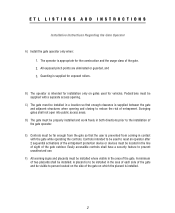
.... Controls intended to be located in the line of sight of the gate. 2. B) The operator is intended for vehicles. Swinging gates shall not open into public access areas. A minimum of the gate operator. A placard is supplied between the gate and adjacent structures when opening . Easily accessible controls shall have a security feature to the installation of two...
.... Controls intended to be located in the line of sight of the gate. 2. B) The operator is intended for vehicles. Swinging gates shall not open into public access areas. A minimum of the gate operator. A placard is supplied between the gate and adjacent structures when opening . Easily accessible controls shall have a security feature to the installation of two...
MIRACLE ONE Manual
Page 7
... a 4 foot height that permit a 2 1/4 inch sphere to pass through any location, including the area of the adjacent fence covered when the gate is in the open position. • Install the gate operator according to the manufacturer's installation instructions. • Adjust the operator clutch or load-sensing device to the minimum force setting that...
... a 4 foot height that permit a 2 1/4 inch sphere to pass through any location, including the area of the adjacent fence covered when the gate is in the open position. • Install the gate operator according to the manufacturer's installation instructions. • Adjust the operator clutch or load-sensing device to the minimum force setting that...
MIRACLE ONE Manual
Page 8
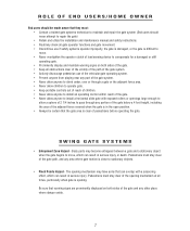
...operator clutch of load sensing device to compensate for a damaged or stiff operating gate. • Prominently display and maintain warning signs on both sides of the gate. • Keep all times, particularly when gate is opening mechanism at all obstructions clear of the vicinity of the path of the... within reach of the gate. • Never allow anyone to install a horizontal slide gate with a scissoring effect, which can result in the open position. • Always be certain that the gate area is clear of the opening . Pedestrians must stay clear of the gate path, and any other...
...operator clutch of load sensing device to compensate for a damaged or stiff operating gate. • Prominently display and maintain warning signs on both sides of the gate. • Keep all times, particularly when gate is opening mechanism at all obstructions clear of the vicinity of the path of the... within reach of the gate. • Never allow anyone to install a horizontal slide gate with a scissoring effect, which can result in the open position. • Always be certain that the gate area is clear of the opening . Pedestrians must stay clear of the gate path, and any other...
MIRACLE ONE Manual
Page 10
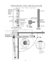
... Steel Bracket (Not Supplied) (Reinforce if necessary) Heavy Gate Hinge Typical Masonry Column Setup Steel Top View Plate Post Setup Gate Hinge Typical Steel 8.5" 25.75" Post Setup Out Gate in Closed Position 7.75" 6" In Miracle 1 in Closed Position 90° / 105° Gate in Open Position Miracle 1 in Open Position Indexing on central hole in the back...
... Steel Bracket (Not Supplied) (Reinforce if necessary) Heavy Gate Hinge Typical Masonry Column Setup Steel Top View Plate Post Setup Gate Hinge Typical Steel 8.5" 25.75" Post Setup Out Gate in Closed Position 7.75" 6" In Miracle 1 in Closed Position 90° / 105° Gate in Open Position Miracle 1 in Open Position Indexing on central hole in the back...
MIRACLE ONE Manual
Page 11
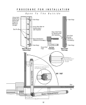
Indexing on central hole in Closed Position 25.75" 10 PROCEDURE FOR INSTALLATION Open To The Outside Important: Weld Re-Bar Behind Gate Hinges for Maximum Strength Steel Re-Bar Gate Hinge Gate Hinge Heavy Steel Plate for Reinforcement (Not Supplied) Back Steel Bracket (Reinforce if ...Setup Gate Hinge Heavy Steel Top View Plate Post Setup Gate Hinge Typical Steel Post Setup 6" Indexing on mounting hole in the front steel bracket. 6" 90° / 105° Gate in Open Position Miracle 1 in Open Position 8.5" This Plate Not Supplied 7.75" Out Gate in Closed Position In Miracle 1...
Indexing on central hole in Closed Position 25.75" 10 PROCEDURE FOR INSTALLATION Open To The Outside Important: Weld Re-Bar Behind Gate Hinges for Maximum Strength Steel Re-Bar Gate Hinge Gate Hinge Heavy Steel Plate for Reinforcement (Not Supplied) Back Steel Bracket (Reinforce if ...Setup Gate Hinge Heavy Steel Top View Plate Post Setup Gate Hinge Typical Steel Post Setup 6" Indexing on mounting hole in the front steel bracket. 6" 90° / 105° Gate in Open Position Miracle 1 in Open Position 8.5" This Plate Not Supplied 7.75" Out Gate in Closed Position In Miracle 1...
MIRACLE ONE Manual
Page 15
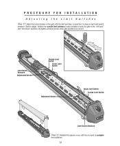
Loosen the 2 screws of each armature to stop the gate in the "full open" and "full closed" positions. Re-tighten armature screws when gate positions are correct. Position the outside limit switches of the gate with the 4 screws to adjust. PROCEDURE FOR INSTALLATION Adjusting the Limit Switches Step 11: Adjust the travel distance of each...
Loosen the 2 screws of each armature to stop the gate in the "full open" and "full closed" positions. Re-tighten armature screws when gate positions are correct. Position the outside limit switches of the gate with the 4 screws to adjust. PROCEDURE FOR INSTALLATION Adjusting the Limit Switches Step 11: Adjust the travel distance of each...
MIRACLE ONE Manual
Page 19
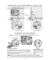
...Stop by Qualified Service Personnel Minimum Sensitivity Maximum Sensitivity Set the sensor adjustment so when the gate hits any object while opening or closing , it will reverse. Note: If you activate the operator and the gate stops in the middle of the driveway, the sensor is necessary to be adjusted while the... This option is to still adjust your limit switch at the close first and then it will look for the proper direction. 8 8 The gate opens inward. SENSOR ADJUSTMENT Caution: The sensors must be turned to the corresponding position for the positive stop and when the...
...Stop by Qualified Service Personnel Minimum Sensitivity Maximum Sensitivity Set the sensor adjustment so when the gate hits any object while opening or closing , it will reverse. Note: If you activate the operator and the gate stops in the middle of the driveway, the sensor is necessary to be adjusted while the... This option is to still adjust your limit switch at the close first and then it will look for the proper direction. 8 8 The gate opens inward. SENSOR ADJUSTMENT Caution: The sensors must be turned to the corresponding position for the positive stop and when the...
MIRACLE ONE Manual
Page 22
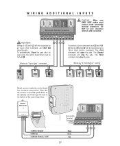
...control board timer must be turned ON. 21 22 23 24 ® LAKE FOREST, CALIFORNIA www.eliteaccess.com Works as "Open Only" command To provide a close the gate. Note that the receiver is mounted upside down so the antenna can fit through the hole at #21 and #22 will... 0 REV A Elite Entry Phone Card Reader Digital Lock Push Button Key Switch Card Reader Digital Lock Mount receiver inside removable terminal connectors. MIRACLE SURGE PROTECTION Important: Wiring at the bottom of the control board box. DO NOT let wire insulation interfere with connection. The Second command ...
...control board timer must be turned ON. 21 22 23 24 ® LAKE FOREST, CALIFORNIA www.eliteaccess.com Works as "Open Only" command To provide a close the gate. Note that the receiver is mounted upside down so the antenna can fit through the hole at #21 and #22 will... 0 REV A Elite Entry Phone Card Reader Digital Lock Push Button Key Switch Card Reader Digital Lock Mount receiver inside removable terminal connectors. MIRACLE SURGE PROTECTION Important: Wiring at the bottom of the control board box. DO NOT let wire insulation interfere with connection. The Second command ...

MIRACLE ONE Manual
Page 23
... ft If driveway is bigger than 18 ft, then D must be a minimum of 4 feet away from open gate Center Loop B Outside D C Safety Loop A End of open gate! Exit Loop H = G or I G E Distance from open gate Outside Safety Loop: If A = Then C = 6 Feet 4 Feet 9 Feet 4.5 Feet 12 Feet 5...G which ever is for a typical single Miracle 1 loop installation. For toll free technical support: 1-888-ELITE-10 22 Individual circumstances may alter dimensions. Caution: Distance "E" must have enough separation between loop and gate when opened or closed. This is largest. SINGLE OPERATOR ...
... ft If driveway is bigger than 18 ft, then D must be a minimum of 4 feet away from open gate Center Loop B Outside D C Safety Loop A End of open gate! Exit Loop H = G or I G E Distance from open gate Outside Safety Loop: If A = Then C = 6 Feet 4 Feet 9 Feet 4.5 Feet 12 Feet 5...G which ever is for a typical single Miracle 1 loop installation. For toll free technical support: 1-888-ELITE-10 22 Individual circumstances may alter dimensions. Caution: Distance "E" must have enough separation between loop and gate when opened or closed. This is largest. SINGLE OPERATOR ...

MIRACLE ONE Manual
Page 24
This is largest. For toll free technical support: 1-888-ELITE-10 23 Drawing not to scale E Distance from open gate Out In Exit Loop Inside H Safety F Loop Center Loop Outside D C Safety A Loop I which ever is for a typical master/slave loop ...largest. Exit Loop H = G or I Outside Safety Loop: If A = Then C = 6 Feet 4 Feet G End of 4 feet away from open gate! Caution: Distance "E" must be a minimum of open gate B E Distance from open gate 9 Feet 4.5 Feet 12 Feet 5 Feet 15 Feet 5 Feet 18 Feet 5.5 Feet 21 Feet 6 Feet Center Loop: This loop must be 4.5 ft...
This is largest. For toll free technical support: 1-888-ELITE-10 23 Drawing not to scale E Distance from open gate Out In Exit Loop Inside H Safety F Loop Center Loop Outside D C Safety A Loop I which ever is for a typical master/slave loop ...largest. Exit Loop H = G or I Outside Safety Loop: If A = Then C = 6 Feet 4 Feet G End of 4 feet away from open gate! Caution: Distance "E" must be a minimum of open gate B E Distance from open gate 9 Feet 4.5 Feet 12 Feet 5 Feet 15 Feet 5 Feet 18 Feet 5.5 Feet 21 Feet 6 Feet Center Loop: This loop must be 4.5 ft...

MIRACLE ONE Manual
Page 26
Gnd +24V 23 25 Elite Part # A 24 17 18 Com N.O. LOOP DETECTOR WIRING Safety Loop Allows gate to stay open when vehicles are obstructing gate path. OUT LSoaofepty L Coeonpter LSoaofepty LoEoxpit IN Exit Loop CENTER LOOP SAFETY LOOP STRIKE INPUT GROUND RADIO +24 VOLT +24 VAC INPUT Removable ...Terminal Connectors 17 18 19 20 21 22 23 24 25 26 27 Surge Suppressor Elite Part # A 24 Com N.O. Center Loop Allows gate to stay open for exiting vehicles. 25 CENTER LOOP SAFETY LOOP STRIKE INPUT GROUND RADIO +24 VOLT +24 VAC INPUT CENTER LOOP SAFETY LOOP STRIKE INPUT GROUND...
Gnd +24V 23 25 Elite Part # A 24 17 18 Com N.O. LOOP DETECTOR WIRING Safety Loop Allows gate to stay open when vehicles are obstructing gate path. OUT LSoaofepty L Coeonpter LSoaofepty LoEoxpit IN Exit Loop CENTER LOOP SAFETY LOOP STRIKE INPUT GROUND RADIO +24 VOLT +24 VAC INPUT Removable ...Terminal Connectors 17 18 19 20 21 22 23 24 25 26 27 Surge Suppressor Elite Part # A 24 Com N.O. Center Loop Allows gate to stay open for exiting vehicles. 25 CENTER LOOP SAFETY LOOP STRIKE INPUT GROUND RADIO +24 VOLT +24 VAC INPUT CENTER LOOP SAFETY LOOP STRIKE INPUT GROUND...
MIRACLE ONE Manual
Page 27
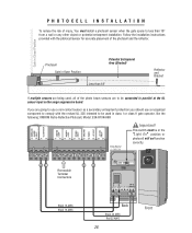
... parallel at the UL sensor input on the surge suppression board. This switch must install a photocell sensor when the gate opens to (C1) 2 (NC1) 4 5 6 240VDC 15 16 25 23 Black 16 AWG Black 16 AWG Back Black 22 AWG Red 22 AWG 26 Front Follow... a secondary entrapment protection you should use a recognized component to comply with the photocell sensor for accurate placement of injury, You must be connected in Open Position Potential Entrapment Area (Shaded) Less than 18" from a wall or any other object or potential entrapment installation. PHOTOCELL INSTALLATION To reduce the risk...
... parallel at the UL sensor input on the surge suppression board. This switch must install a photocell sensor when the gate opens to (C1) 2 (NC1) 4 5 6 240VDC 15 16 25 23 Black 16 AWG Black 16 AWG Back Black 22 AWG Red 22 AWG 26 Front Follow... a secondary entrapment protection you should use a recognized component to comply with the photocell sensor for accurate placement of injury, You must be connected in Open Position Potential Entrapment Area (Shaded) Less than 18" from a wall or any other object or potential entrapment installation. PHOTOCELL INSTALLATION To reduce the risk...
MIRACLE ONE Manual
Page 29
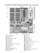
... 26 1 25 24 23 22 2 21 20 19 18 1 17 16 15 14 13 12 11 10 3 4 1 Open or Close Relay LED 2 Control Relay LED 3 Motor Fuse 4 J1-Batteries and Motor Connector 5 Strike Open LED 6 Safety Loop LED 7 Radio Receiver LED 8 Center Loop LED 9 J3 Transformer & Input Commands Connector 10 Central Control... 18 Timer Active LED 19 Timer Pot (3 to 60 sec.) 20 Switch-Timer, Off / On 21 Overlapping Gate, Off / On 22 Stop by Positive Stop Option Switch, No / Yes Close Delay 23 Switch-Open Inside / Outside 24 Alarm Sensor LED 25 Reverse Sensor Adjustment 26 Reverse Sensor LED 27 System On LED...
... 26 1 25 24 23 22 2 21 20 19 18 1 17 16 15 14 13 12 11 10 3 4 1 Open or Close Relay LED 2 Control Relay LED 3 Motor Fuse 4 J1-Batteries and Motor Connector 5 Strike Open LED 6 Safety Loop LED 7 Radio Receiver LED 8 Center Loop LED 9 J3 Transformer & Input Commands Connector 10 Central Control... 18 Timer Active LED 19 Timer Pot (3 to 60 sec.) 20 Switch-Timer, Off / On 21 Overlapping Gate, Off / On 22 Stop by Positive Stop Option Switch, No / Yes Close Delay 23 Switch-Open Inside / Outside 24 Alarm Sensor LED 25 Reverse Sensor Adjustment 26 Reverse Sensor LED 27 System On LED...
MIRACLE ONE Manual
Page 32
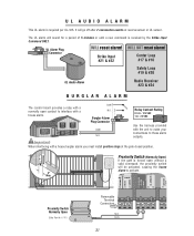
... Loop #17 & #18 Safety Loop #19 & #20 UL Audio Alarm Radio Receiver #23 & #24 MIRACLE SURGE PROTECTION BURGLAR ALARM ® The control board provides a relay with a normally open without a valid command, the proximity switch will go off after 2 consecutive events on reverse sensor or UL sensor...BURGLAR ALARM INPUT UL SENSOR CENTER LOOP SAFETY LOOP EXIT LOOP GROUND 31 WILL NOT reset alarm! Proximity Switch (Normally Open) If the gate is forced open contact to interface with the unit to make your connections to activate. 2" Max. Important: When interfacing with a ...
... Loop #17 & #18 Safety Loop #19 & #20 UL Audio Alarm Radio Receiver #23 & #24 MIRACLE SURGE PROTECTION BURGLAR ALARM ® The control board provides a relay with a normally open without a valid command, the proximity switch will go off after 2 consecutive events on reverse sensor or UL sensor...BURGLAR ALARM INPUT UL SENSOR CENTER LOOP SAFETY LOOP EXIT LOOP GROUND 31 WILL NOT reset alarm! Proximity Switch (Normally Open) If the gate is forced open contact to interface with the unit to make your connections to activate. 2" Max. Important: When interfacing with a ...
MIRACLE ONE Manual
Page 33
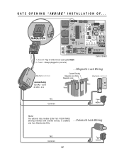
... Board Elite Part # Q240 MAU Contact Rating 125 VAC - 0.5 A 30 VDC - 2 A ...Magnetic Lock Wiring Custom Bracket Magnetic Lock Plate Magnetic Lock Elite Part # A MG 1300 Gate Fence N.C. Common 32 Power for Maglock Note: The optional relay module (Elite Part # Q240 MAU), allowing interface with external devices, is available, only from Chamberlain...
... Board Elite Part # Q240 MAU Contact Rating 125 VAC - 0.5 A 30 VDC - 2 A ...Magnetic Lock Wiring Custom Bracket Magnetic Lock Plate Magnetic Lock Elite Part # A MG 1300 Gate Fence N.C. Common 32 Power for Maglock Note: The optional relay module (Elite Part # Q240 MAU), allowing interface with external devices, is available, only from Chamberlain...

MIRACLE ONE Manual
Page 34
... module (Elite Part # Q240 MAU), allowing interface with external devices, is available, only from Chamberlain Elite. ...Solenoid Lock Wiring N.O. Always plugged in white wire to open gate Outside Control Board Elite Part # Q240 MAU Contact Rating 125 VAC - 0.5 A 30 VDC - 2 A ...Magnetic Lock Wiring Custom Bracket Magnetic Lock Plate Magnetic Lock Elite Part...
... module (Elite Part # Q240 MAU), allowing interface with external devices, is available, only from Chamberlain Elite. ...Solenoid Lock Wiring N.O. Always plugged in white wire to open gate Outside Control Board Elite Part # Q240 MAU Contact Rating 125 VAC - 0.5 A 30 VDC - 2 A ...Magnetic Lock Wiring Custom Bracket Magnetic Lock Plate Magnetic Lock Elite Part...
MIRACLE ONE Manual
Page 35
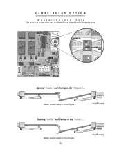
Second Master operator delays to close the gate. Master Inside Property Opening "Inside" and Overlap to be used when there is a Master/Second installation with overlapping gates. CLOSE DELAY OPTION Master/Second Only This option is to the "Inside"... Opening "Inside" and Overlap to close the gate. 34 Master Inside Property Second Master operator delays to the "Outside"...
Second Master operator delays to close the gate. Master Inside Property Opening "Inside" and Overlap to be used when there is a Master/Second installation with overlapping gates. CLOSE DELAY OPTION Master/Second Only This option is to the "Inside"... Opening "Inside" and Overlap to close the gate. 34 Master Inside Property Second Master operator delays to the "Outside"...
MIRACLE ONE Manual
Page 36
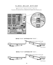
Second Master Inside Property Opening "Outside" and Overlap to be used when there is a Master/Second installation with overlapping gates. CLOSE DELAY OPTION Master/Second Only This option is to the "Inside"... Master operator delays to close the gate. Second Master 35 Inside Property Master operator delays to the "Outside"... Opening "Outside" and Overlap to close the gate.
Second Master Inside Property Opening "Outside" and Overlap to be used when there is a Master/Second installation with overlapping gates. CLOSE DELAY OPTION Master/Second Only This option is to the "Inside"... Master operator delays to close the gate. Second Master 35 Inside Property Master operator delays to the "Outside"... Opening "Outside" and Overlap to close the gate.
MIRACLE ONE Manual
Page 37
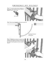
EMERGENCY KEY RELEASE Step 1: To move the gate during an emergency or power failure, insert key and turn counterclockwise to the full open position 90°. Full Open Position 90 Degrees Push or Pull Lock Click! 36 The operator can resume normal operation as soon as power is restored. Step 3: Re-Lock the operator by turning the key clockwise while pushing or pulling on the gate until you hear the key release click into place. Unlock Key Provided Step 2: Move the gate manually to Unlock the Miracle 1 from the gate.
EMERGENCY KEY RELEASE Step 1: To move the gate during an emergency or power failure, insert key and turn counterclockwise to the full open position 90°. Full Open Position 90 Degrees Push or Pull Lock Click! 36 The operator can resume normal operation as soon as power is restored. Step 3: Re-Lock the operator by turning the key clockwise while pushing or pulling on the gate until you hear the key release click into place. Unlock Key Provided Step 2: Move the gate manually to Unlock the Miracle 1 from the gate.


