

MIRACLE ONE Manual
Page 2
...Board Description Alarm / Maglock Control Board Connections UL Audio Alarm Burglar Alarm and Proximity Switch "Gate Opening Inside" Installation of Maglock / Solenoid Relay "Gate Opening Outside" Installation of this manual may be reproduced in this handbook are an Authorized ...No part of Maglock / Solenoid Relay Close Delay Option (Master / Second Only) Emergency Key Release Troubleshooting Optional Solar Power Miracle 1 Accessories Miracle 1 Parts Illustration Miracle 1 Parts List / Maintenance Features and Specifications Quick Reference Surge Suppressor Wiring Diagram 2-5 6 6 7 7 8 9 10 ...
...Board Description Alarm / Maglock Control Board Connections UL Audio Alarm Burglar Alarm and Proximity Switch "Gate Opening Inside" Installation of Maglock / Solenoid Relay "Gate Opening Outside" Installation of this manual may be reproduced in this handbook are an Authorized ...No part of Maglock / Solenoid Relay Close Delay Option (Master / Second Only) Emergency Key Release Troubleshooting Optional Solar Power Miracle 1 Accessories Miracle 1 Parts Illustration Miracle 1 Parts List / Maintenance Features and Specifications Quick Reference Surge Suppressor Wiring Diagram 2-5 6 6 7 7 8 9 10 ...
MIRACLE ONE Manual
Page 3
.... Controls intended to be located in the area of the gate. F) All warning signs and placards must be used for exposed rollers. Swinging gates shall not open into public access areas. D) The gate must be visible to reset an operator after 2 sequential activations... device or devices must be supplied with the gate while operating the controls. ETL LISTINGS AND INSTRUCTIONS Installation Instructions Regarding the Gate Operator A) Install the gate operator only when: 1. B) The operator is supplied between the gate and adjacent structures when opening . All exposed ...
.... Controls intended to be located in the area of the gate. F) All warning signs and placards must be used for exposed rollers. Swinging gates shall not open into public access areas. D) The gate must be visible to reset an operator after 2 sequential activations... device or devices must be supplied with the gate while operating the controls. ETL LISTINGS AND INSTRUCTIONS Installation Instructions Regarding the Gate Operator A) Install the gate operator only when: 1. B) The operator is supplied between the gate and adjacent structures when opening . All exposed ...
MIRACLE ONE Manual
Page 4
... A hard wired contact sensor shall be located and its arc of a swing gate. A wireless contact sensor such as a photo beam: 1. ETL LISTINGS AND INSTRUCTIONS G) For a gate operator utilizing a non-contact sensor such as the one or more contact sensors shall be located on the bottom edge. 3 See instructions... on the inside and outside leading edge of travel, one that the communication between the sensor and the gate operator is not subjected to the gate operator for each type of entrapment or obstruction exists, such as an edge sensor: 1. A ...
... A hard wired contact sensor shall be located and its arc of a swing gate. A wireless contact sensor such as a photo beam: 1. ETL LISTINGS AND INSTRUCTIONS G) For a gate operator utilizing a non-contact sensor such as the one or more contact sensors shall be located on the bottom edge. 3 See instructions... on the inside and outside leading edge of travel, one that the communication between the sensor and the gate operator is not subjected to the gate operator for each type of entrapment or obstruction exists, such as an edge sensor: 1. A ...
MIRACLE ONE Manual
Page 5
... the limit of injury or death: 1. Have a qualified service person make repairs to adjust and retest the gate operator properly can increase the risk of injury or death. 5. NO ONE SHOULD CROSS THE PATH OF A MOVING GATE! 4. The entrance is not moving. Make sure the power for vehicles only. Never let children operate...
... the limit of injury or death: 1. Have a qualified service person make repairs to adjust and retest the gate operator properly can increase the risk of injury or death. 5. NO ONE SHOULD CROSS THE PATH OF A MOVING GATE! 4. The entrance is not moving. Make sure the power for vehicles only. Never let children operate...
MIRACLE ONE Manual
Page 6
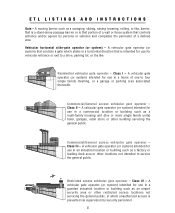
...barrier or is prevented via supervision by persons or vehicles and completes the perimeter of one-to service the general public. Commercial/General access vehicular gate operator - A vehicular gate operator (or system) intended for vehicular entrance or exit to a drive, parking lot...location or building such as a factory or loading dock area or other building servicing the general public. Commercial/General access vehicular gate operator - A vehicular gate operator (or system) intended for use in a commercial location or building such as a swinging, sliding, raising lowering, ...
...barrier or is prevented via supervision by persons or vehicles and completes the perimeter of one-to service the general public. Commercial/General access vehicular gate operator - A vehicular gate operator (or system) intended for vehicular entrance or exit to a drive, parking lot...location or building such as a factory or loading dock area or other building servicing the general public. Commercial/General access vehicular gate operator - A vehicular gate operator (or system) intended for use in a commercial location or building such as a swinging, sliding, raising lowering, ...
MIRACLE ONE Manual
Page 7
...safety features of the entire system including the entrapment protection devices, and explain the need for the application. • Confirm that the gate is performed routinely. • Offer the owner/end user a maintenance contract, or contact them regularly to operate the manual disconnect feature... 2 1/4 inch sphere to pass through any location, including the area of the adjacent fence covered when the gate is in the open position. • Install the gate operator according to the manufacturer's installation instructions. • Adjust the operator clutch or load-sensing device to the ...
...safety features of the entire system including the entrapment protection devices, and explain the need for the application. • Confirm that the gate is performed routinely. • Offer the owner/end user a maintenance contract, or contact them regularly to operate the manual disconnect feature... 2 1/4 inch sphere to pass through any location, including the area of the adjacent fence covered when the gate is in the open position. • Install the gate operator according to the manufacturer's installation instructions. • Adjust the operator clutch or load-sensing device to the ...

MIRACLE ONE Manual
Page 8
...the opening mechanism at all obstructions clear of the vicinity of the path of the gate system. • Actively discourage pedestrian use if safety systems operate improperly, the gate is damaged, or the gate is difficult to move , which can result in serious injury or death. The ...portable controls out of reach of children. • Never allow anyone to install an operating control within reach of the gate. • Never allow anyone to install a horizontal slide gate with a scissoring effect, which can overlap with exposed rollers or openings large enough to allow a sphere of 2 1/4 ...
...the opening mechanism at all obstructions clear of the vicinity of the path of the gate system. • Actively discourage pedestrian use if safety systems operate improperly, the gate is damaged, or the gate is difficult to move , which can result in serious injury or death. The ...portable controls out of reach of children. • Never allow anyone to install an operating control within reach of the gate. • Never allow anyone to install a horizontal slide gate with a scissoring effect, which can overlap with exposed rollers or openings large enough to allow a sphere of 2 1/4 ...
MIRACLE ONE Manual
Page 9
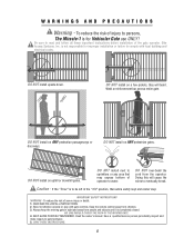
...away from people and objects until it is completely closed. Keep the remote control away from the operator. NO ONE SHOULD CROSS THE PATH OF THE MOVING GATE. 4. Have a qualified service person periodically inspect and make repairs to eventually break. SAVE THESE INSTRUCTIONS. 8 Be... owner's manual. Elite Access Systems, Inc. Weld a reinforcement bar across entire gate. WARNINGS AND PRECAUTIONS Warning - is for improper installation or failure to persons, The Miracle-1 is not responsible for Vehicular Gate use ONLY! DO NOT install on ANY pedestrian passageways or doorways. Never let ...
...away from people and objects until it is completely closed. Keep the remote control away from the operator. NO ONE SHOULD CROSS THE PATH OF THE MOVING GATE. 4. Have a qualified service person periodically inspect and make repairs to eventually break. SAVE THESE INSTRUCTIONS. 8 Be... owner's manual. Elite Access Systems, Inc. Weld a reinforcement bar across entire gate. WARNINGS AND PRECAUTIONS Warning - is for improper installation or failure to persons, The Miracle-1 is not responsible for Vehicular Gate use ONLY! DO NOT install on ANY pedestrian passageways or doorways. Never let ...
MIRACLE ONE Manual
Page 10
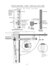
... Steel Bracket (Not Supplied) (Reinforce if necessary) Heavy Gate Hinge Typical Masonry Column Setup Steel Top View Plate Post Setup Gate Hinge Typical Steel 8.5" 25.75" Post Setup Out Gate in Closed Position 7.75" 6" In Miracle 1 in Closed Position 90° / 105° Gate in Open Position Miracle 1 in Open Position Indexing on central hole in...
... Steel Bracket (Not Supplied) (Reinforce if necessary) Heavy Gate Hinge Typical Masonry Column Setup Steel Top View Plate Post Setup Gate Hinge Typical Steel 8.5" 25.75" Post Setup Out Gate in Closed Position 7.75" 6" In Miracle 1 in Closed Position 90° / 105° Gate in Open Position Miracle 1 in Open Position Indexing on central hole in...
MIRACLE ONE Manual
Page 11
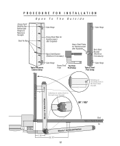
...Bracket (Reinforce if necessary) Typical Masonry Column Setup Gate Hinge Heavy Steel Top View Plate Post Setup Gate Hinge Typical Steel Post Setup 6" Indexing on mounting hole in the front steel bracket. 6" 90° / 105° Gate in Open Position Miracle 1 in Open Position 8.5" This Plate Not ...Supplied 7.75" Out Gate in Closed Position In Miracle 1 in the back ...
...Bracket (Reinforce if necessary) Typical Masonry Column Setup Gate Hinge Heavy Steel Top View Plate Post Setup Gate Hinge Typical Steel Post Setup 6" Indexing on mounting hole in the front steel bracket. 6" 90° / 105° Gate in Open Position Miracle 1 in Open Position 8.5" This Plate Not ...Supplied 7.75" Out Gate in Closed Position In Miracle 1 in the back ...
MIRACLE ONE Manual
Page 12
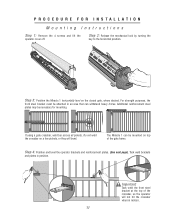
... operator brackets and reinforcement plates. (See next page). Step 2: Release the mechanical lock by turning the key to the horizontal position. The Miracle 1 can withstand heavy forces. For strength purposes, the front steel bracket must be attached in an area that can be necessary for mounting.... Do not weld the crossbar on the closed gate, where desired. Step 3: Position the Miracle 1 horizontally level on a few pickets, or they will not hit the crossbar when in position. Additional reinforcement steel plates...
... operator brackets and reinforcement plates. (See next page). Step 2: Release the mechanical lock by turning the key to the horizontal position. The Miracle 1 can withstand heavy forces. For strength purposes, the front steel bracket must be attached in an area that can be necessary for mounting.... Do not weld the crossbar on the closed gate, where desired. Step 3: Position the Miracle 1 horizontally level on a few pickets, or they will not hit the crossbar when in position. Additional reinforcement steel plates...
MIRACLE ONE Manual
Page 13
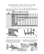
... operator attached to Step 7 2.25" Vertical Height Difference Step 5: With the operator removed, completely weld around the brackets and plates on the gate. Step 6: Remove the nut, bolt and bushing from the traveler carriage at the front of the operator. Traveler Carriage Front Bracket 12 Make ...nut and bolt (See Below). Secure operator with the washer and nut (See Below). PROCEDURE FOR INSTALLATION Mounting Instructions Step 4 (con't): The gate must be in position. Place the metal bushing in the hole of front bracket. Important: These nuts MUST be tight or unit will be ...
... operator attached to Step 7 2.25" Vertical Height Difference Step 5: With the operator removed, completely weld around the brackets and plates on the gate. Step 6: Remove the nut, bolt and bushing from the traveler carriage at the front of the operator. Traveler Carriage Front Bracket 12 Make ...nut and bolt (See Below). Secure operator with the washer and nut (See Below). PROCEDURE FOR INSTALLATION Mounting Instructions Step 4 (con't): The gate must be in position. Place the metal bushing in the hole of front bracket. Important: These nuts MUST be tight or unit will be ...
MIRACLE ONE Manual
Page 14
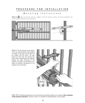
... finishes the basic mounting of the operator to fail prematurely. After completing all electrical connections to complete the final adjustments on the gate until you hear the key release click into place. The gate should not move after the operator has been locked. An off-level installation may cause the... gate or operator to the gate. PROCEDURE FOR INSTALLATION Mounting Instructions Step 8: Make sure that the operator is level or it will not function properly. Step 10: The following ...
... finishes the basic mounting of the operator to fail prematurely. After completing all electrical connections to complete the final adjustments on the gate until you hear the key release click into place. The gate should not move after the operator has been locked. An off-level installation may cause the... gate or operator to the gate. PROCEDURE FOR INSTALLATION Mounting Instructions Step 8: Make sure that the operator is level or it will not function properly. Step 10: The following ...
MIRACLE ONE Manual
Page 15
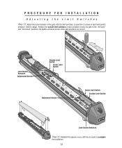
... are correct. PROCEDURE FOR INSTALLATION Adjusting the Limit Switches Step 11: Adjust the travel distance of the gate with the 4 screws to complete the installation. 14 Slide to stop the gate in the "full open" and "full closed" positions. Limit Switch Armature Adjustment Screws Outside Limit Switch Inside Limit Switch Adjustment Screws...
... are correct. PROCEDURE FOR INSTALLATION Adjusting the Limit Switches Step 11: Adjust the travel distance of the gate with the 4 screws to complete the installation. 14 Slide to stop the gate in the "full open" and "full closed" positions. Limit Switch Armature Adjustment Screws Outside Limit Switch Inside Limit Switch Adjustment Screws...
MIRACLE ONE Manual
Page 19
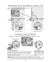
...look for the limit close first and then it will stop . 18 Option - CHOOSING GATE MOVEMENT DIRECTION Switch the "Open Inside / Open Outside" switch on the control board to "yes" if the gate will use positive stops at the close position. Stop This option is to be adjusted while... the close position. Important: It is set too sensitive. Note: If you activate the operator and the gate stops in the opening , it will look for the proper direction. 8 8 The gate opens inward. SENSOR ADJUSTMENT Caution: The sensors must be turned to the corresponding position for the positive stop...
...look for the limit close first and then it will stop . 18 Option - CHOOSING GATE MOVEMENT DIRECTION Switch the "Open Inside / Open Outside" switch on the control board to "yes" if the gate will use positive stops at the close position. Stop This option is to be adjusted while... the close position. Important: It is set too sensitive. Note: If you activate the operator and the gate stops in the opening , it will look for the proper direction. 8 8 The gate opens inward. SENSOR ADJUSTMENT Caution: The sensors must be turned to the corresponding position for the positive stop...
MIRACLE ONE Manual
Page 20
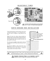
...rod for the ground wire. Never splice two wires for your area. 8 Ft The ground wire must be directed towards the Elite gate operator. Connect ground wire to green wire from which to dissipate its integrity, replace it with all necessary local building codes. 19 Timer... 1 to comply with a single wire length. Without this path, the intense energy generated by lightning could be located within 3 feet from the gate operator. EARTH GROUND ROD INSTALLATION Proper grounding gives an electrical charge, such as from an electrical static discharge or a near lightning strike, a path...
...rod for the ground wire. Never splice two wires for your area. 8 Ft The ground wire must be directed towards the Elite gate operator. Connect ground wire to green wire from which to dissipate its integrity, replace it with all necessary local building codes. 19 Timer... 1 to comply with a single wire length. Without this path, the intense energy generated by lightning could be located within 3 feet from the gate operator. EARTH GROUND ROD INSTALLATION Proper grounding gives an electrical charge, such as from an electrical static discharge or a near lightning strike, a path...
MIRACLE ONE Manual
Page 22
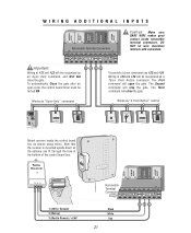
MIRACLE SURGE PROTECTION Important: Wiring at #23 and #24 will be recognized as a Three Push Button command. To automatically Close the gate after an open the gate. Wiring at #21 and #22 will stop the gate. The First command will close the gate. Note that the receiver is mounted upside down so the antenna can fit... Digital Lock Push Button Key Switch Card Reader Digital Lock Mount receiver inside removable terminal connectors. Works as "Open Only" command To provide a close the gate.
MIRACLE SURGE PROTECTION Important: Wiring at #23 and #24 will be recognized as a Three Push Button command. To automatically Close the gate after an open the gate. Wiring at #21 and #22 will stop the gate. The First command will close the gate. Note that the receiver is mounted upside down so the antenna can fit... Digital Lock Push Button Key Switch Card Reader Digital Lock Mount receiver inside removable terminal connectors. Works as "Open Only" command To provide a close the gate.

MIRACLE ONE Manual
Page 23
... is largest. For toll free technical support: 1-888-ELITE-10 22 Exit Loop H = G or I G E Distance from open gate Center Loop B Outside D C Safety Loop A End of 4 feet away from open gate Outside Safety Loop: If A = Then C = 6 Feet 4 Feet 9 Feet 4.5 Feet 12 Feet 5 Feet 15 Feet 5 Feet...there is no center loop, then F 4 ft If there is a center loop, then F = B or G which ever is for a typical single Miracle 1 loop installation. Out In Drawing not to scale Exit Loop Inside H Safety Loop F I which ever is VERY important to prevent false detection. Individual ...
... is largest. For toll free technical support: 1-888-ELITE-10 22 Exit Loop H = G or I G E Distance from open gate Center Loop B Outside D C Safety Loop A End of 4 feet away from open gate Outside Safety Loop: If A = Then C = 6 Feet 4 Feet 9 Feet 4.5 Feet 12 Feet 5 Feet 15 Feet 5 Feet...there is no center loop, then F 4 ft If there is a center loop, then F = B or G which ever is for a typical single Miracle 1 loop installation. Out In Drawing not to scale Exit Loop Inside H Safety Loop F I which ever is VERY important to prevent false detection. Individual ...

MIRACLE ONE Manual
Page 24
... driveway is smaller than 18 ft, then D must be 4.5 ft If driveway is bigger than 18 ft, then D must be a minimum of open gate B E Distance from open gate 9 Feet 4.5 Feet 12 Feet 5 Feet 15 Feet 5 Feet 18 Feet 5.5 Feet 21 Feet 6 Feet Center Loop: This loop must be 5 ft...loop installation. Exit Loop H = G or I Outside Safety Loop: If A = Then C = 6 Feet 4 Feet G End of 4 feet away from open gate! For toll free technical support: 1-888-ELITE-10 23 Drawing not to prevent false detection. This is largest. Individual circumstances may alter dimensions. MASTER/SECOND...
... driveway is smaller than 18 ft, then D must be 4.5 ft If driveway is bigger than 18 ft, then D must be a minimum of open gate B E Distance from open gate 9 Feet 4.5 Feet 12 Feet 5 Feet 15 Feet 5 Feet 18 Feet 5.5 Feet 21 Feet 6 Feet Center Loop: This loop must be 5 ft...loop installation. Exit Loop H = G or I Outside Safety Loop: If A = Then C = 6 Feet 4 Feet G End of 4 feet away from open gate! For toll free technical support: 1-888-ELITE-10 23 Drawing not to prevent false detection. This is largest. Individual circumstances may alter dimensions. MASTER/SECOND...

MIRACLE ONE Manual
Page 26
Gnd +24V 21 22 23 25 Allows gate to automatically open for exiting vehicles. 25 OUT LSoaofepty L Coeonpter LSoaofepty LoEoxpit IN Exit Loop CENTER LOOP SAFETY LOOP STRIKE INPUT GROUND RADIO +24 VOLT +... +24V 23 25 For fail safe operation, connect safety loops in series. Gnd +24V 23 25 Elite Part # A 24 17 18 Com N.O. Center Loop Allows gate to stay open when vehicles are obstructing gate path. LOOP DETECTOR WIRING Safety Loop Allows gate to stay open when vehicles are obstructing...
Gnd +24V 21 22 23 25 Allows gate to automatically open for exiting vehicles. 25 OUT LSoaofepty L Coeonpter LSoaofepty LoEoxpit IN Exit Loop CENTER LOOP SAFETY LOOP STRIKE INPUT GROUND RADIO +24 VOLT +... +24V 23 25 For fail safe operation, connect safety loops in series. Gnd +24V 23 25 Elite Part # A 24 17 18 Com N.O. Center Loop Allows gate to stay open when vehicles are obstructing gate path. LOOP DETECTOR WIRING Safety Loop Allows gate to stay open when vehicles are obstructing...


