
MT5011E Installation Manual
Page 1
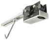
INSTALLATION MANUAL MODEL MT5011E/BMT5011E MEDIUM DUTY DOOR OPERATOR RaNdoBiwuoiRlwteiitcnheiver INTENDED FOR PROFESSIONAL INSTALLATION ONLY Visit www.LiftMaster.com to locate a professional installing dealer in your area. 2 YEAR WARRANTY Serial # (located on electrical box) Installation Date Radio Receiver Built on Board 315MHz NOT FOR RESIDENTIAL USE A SAFETY DEVICE IS HIGHLY RECOMMENDED.
INSTALLATION MANUAL MODEL MT5011E/BMT5011E MEDIUM DUTY DOOR OPERATOR RaNdoBiwuoiRlwteiitcnheiver INTENDED FOR PROFESSIONAL INSTALLATION ONLY Visit www.LiftMaster.com to locate a professional installing dealer in your area. 2 YEAR WARRANTY Serial # (located on electrical box) Installation Date Radio Receiver Built on Board 315MHz NOT FOR RESIDENTIAL USE A SAFETY DEVICE IS HIGHLY RECOMMENDED.

MT5011E Installation Manual
Page 2
...alert you to the possibility of damage to the possibility of your door and/or the door operator if you do not comply with the cautionary statements that WARNING accompany them carefully. AAVTTEERNTTISIOSNEMENT 2 WARNING ...AVERTISSEMENT AVERTISSEMENT TABLE OF CONTENTS SAFETY INFORMATION 2 APPLICATION 3 OPERATOR DIMENSIONS 4 OPERATOR SPECIFICATIONS 4 CARTON INVENTORY 5 PREPARATION 5 ASSEMBLY 6-8 TYPICAL INSTALLATION 9-14 ADJUSTMENT 14-15 OPTIONAL SAFETY DEVICE CONFIGURATIONS ...
...alert you to the possibility of damage to the possibility of your door and/or the door operator if you do not comply with the cautionary statements that WARNING accompany them carefully. AAVTTEERNTTISIOSNEMENT 2 WARNING ...AVERTISSEMENT AVERTISSEMENT TABLE OF CONTENTS SAFETY INFORMATION 2 APPLICATION 3 OPERATOR DIMENSIONS 4 OPERATOR SPECIFICATIONS 4 CARTON INVENTORY 5 PREPARATION 5 ASSEMBLY 6-8 TYPICAL INSTALLATION 9-14 ADJUSTMENT 14-15 OPTIONAL SAFETY DEVICE CONFIGURATIONS ...
MT5011E Installation Manual
Page 3
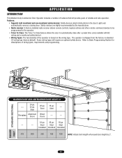
...Wood Doors --- --- 24 ga. 20 ga. 16 ga. --- --- APPLICATION INTRODUCTION This Medium Duty Commercial Door Operator includes a number of features that will require an optional safety device. The operator is based on the wiring type. Steel --- Features: • Supports both monitored and non-monitored safety devices... A factory installed radio receiver allows remote controls, keyless entries and other remote command devices to be programmed to the operator. • Timer To Close: The Timer To Close feature allows the door to Basic Programming Section for descriptions of the...
...Wood Doors --- --- 24 ga. 20 ga. 16 ga. --- --- APPLICATION INTRODUCTION This Medium Duty Commercial Door Operator includes a number of features that will require an optional safety device. The operator is based on the wiring type. Steel --- Features: • Supports both monitored and non-monitored safety devices... A factory installed radio receiver allows remote controls, keyless entries and other remote command devices to be programmed to the operator. • Timer To Close: The Timer To Close feature allows the door to Basic Programming Section for descriptions of the...
MT5011E Installation Manual
Page 4
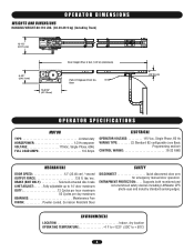
...LIMIT ADJUST:. . . . . .Fully adjustable up to + 50˚C) 4 Supports both monitored and non-monitored safety devices including LiftMaster CPS photo-eyes and industry standard sensing edges. OPERATOR DIMENSIONS WEIGHTS AND DIMENSIONS HANGING WEIGHT:80-110 LBS. (36.29-49.9 kg) (Including Track) 12-1/2" (31.75 cm) 9-1/2"...CONTROL WIRING 16-22 AWG MECHANICAL DOOR SPEED 12" (30.48 cm) / second OUTPUT FORCE 125 ft. ENVIRONMENTAL LOCATION Indoor, dry location OPERATING TEMPERATURE 4˚ F to +122˚F (-20C˚ to 14' door maximum DUTY 12 Cycles per hour maximum 50 Cycles per day ...
...LIMIT ADJUST:. . . . . .Fully adjustable up to + 50˚C) 4 Supports both monitored and non-monitored safety devices including LiftMaster CPS photo-eyes and industry standard sensing edges. OPERATOR DIMENSIONS WEIGHTS AND DIMENSIONS HANGING WEIGHT:80-110 LBS. (36.29-49.9 kg) (Including Track) 12-1/2" (31.75 cm) 9-1/2"...CONTROL WIRING 16-22 AWG MECHANICAL DOOR SPEED 12" (30.48 cm) / second OUTPUT FORCE 125 ft. ENVIRONMENTAL LOCATION Indoor, dry location OPERATING TEMPERATURE 4˚ F to +122˚F (-20C˚ to 14' door maximum DUTY 12 Cycles per hour maximum 50 Cycles per day ...
MT5011E Installation Manual
Page 5
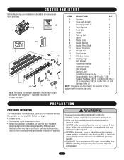
...INJURY. • Disable ALL locks and remove ALL ropes connected to door BEFORE installing and operating door operator to avoid entanglement. Actual track length will vary due to particular building characteristics, refer to the following general ... Before beginning your installation check that all components were provided. 15 1 14 ^ ^OPEN CLOSE O STOP 8 4 10 9 7 2 12 3 13 11 6 5 ITEM DESCRIPTION QTY 1 Operator 1 2 Track (left & right) Door height plus 2' 2 3 Track Spacers 2 4 Front Idler 1 5 Trolley 1 6 Take-up Bolt 1 7 Chain 1 8 Master Links 2 ...
...INJURY. • Disable ALL locks and remove ALL ropes connected to door BEFORE installing and operating door operator to avoid entanglement. Actual track length will vary due to particular building characteristics, refer to the following general ... Before beginning your installation check that all components were provided. 15 1 14 ^ ^OPEN CLOSE O STOP 8 4 10 9 7 2 12 3 13 11 6 5 ITEM DESCRIPTION QTY 1 Operator 1 2 Track (left & right) Door height plus 2' 2 3 Track Spacers 2 4 Front Idler 1 5 Trolley 1 6 Take-up Bolt 1 7 Chain 1 8 Master Links 2 ...
MT5011E Installation Manual
Page 6
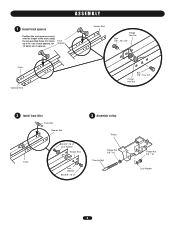
For doors up to 12' use 2 track spacers, for 14' doors use 3 spacers. Track Spacers Header End Flange Hex Nut Bolt 3/8" - 16 x 3/4" Track Operator End Bolt 3/8" - 16 x 3/4" Flange Hex Nut 2 Install front idler Front Idler Header End Track Bolt 3/8" -16 x 1" Lock Washer Header End Lock Washer Bolt 3/8" -16 x 1" 3 Assemble trolley Trolley Flange Nut 3/8" - 16 Take-Up Bolt Flange Nut 3/8" - 16 Lock Washer 6 ASSEMBLY 1 Install track spacers Position the track spacers evenly over the length of the track using the pre-punched holes.
For doors up to 12' use 2 track spacers, for 14' doors use 3 spacers. Track Spacers Header End Flange Hex Nut Bolt 3/8" - 16 x 3/4" Track Operator End Bolt 3/8" - 16 x 3/4" Flange Hex Nut 2 Install front idler Front Idler Header End Track Bolt 3/8" -16 x 1" Lock Washer Header End Lock Washer Bolt 3/8" -16 x 1" 3 Assemble trolley Trolley Flange Nut 3/8" - 16 Take-Up Bolt Flange Nut 3/8" - 16 Lock Washer 6 ASSEMBLY 1 Install track spacers Position the track spacers evenly over the length of the track using the pre-punched holes.

MT5011E Installation Manual
Page 7
4 Slide trolley onto the track ASSEMBLY Track Operator End Track Trolley Operator End Trolley 5 Attach track to operator Flange Hex Nut Track Flange Hex Nut Bolt 3/8" - 16 x 3/4" Operator End Bolt 3/8" - 16 x 3/4" Operator 7 Header End Bolt 3/8" - 16 x 3/4" Flange Hex Nut Bolt 3/8" - 16 x 3/4"
4 Slide trolley onto the track ASSEMBLY Track Operator End Track Trolley Operator End Trolley 5 Attach track to operator Flange Hex Nut Track Flange Hex Nut Bolt 3/8" - 16 x 3/4" Operator End Bolt 3/8" - 16 x 3/4" Operator 7 Header End Bolt 3/8" - 16 x 3/4" Flange Hex Nut Bolt 3/8" - 16 x 3/4"
MT5011E Installation Manual
Page 8
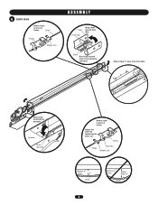
6 Install chain Attach chain to front of trolley Chain Trolley Master Link ASSEMBLY Track Front Idler Wrap chain around front idler Chain Run chain around track in the direction indicated Slide trolley 2" away from front idler 2" Wrap chain around drive sprocket Operator Drive Sprocket Attach chain to back of trolley Adjust the chain by tightening the inner nut Trolley Chain Inner Nut Master Link Bottom of Track 3" Chain 8 Bottom of Track More than 3" Chain
6 Install chain Attach chain to front of trolley Chain Trolley Master Link ASSEMBLY Track Front Idler Wrap chain around front idler Chain Run chain around track in the direction indicated Slide trolley 2" away from front idler 2" Wrap chain around drive sprocket Operator Drive Sprocket Attach chain to back of trolley Adjust the chain by tightening the inner nut Trolley Chain Inner Nut Master Link Bottom of Track 3" Chain 8 Bottom of Track More than 3" Chain

MT5011E Installation Manual
Page 9
... travel Level Header Wall High Point of the door. TYPICAL INSTALLATION DETERMINE HEADER BRACKET MOUNTING LOCATION The trolley operator is generally mounted over the center of door stile / top section support. Typically, the operator may be mounted up to 24" (60.96 cm) off center mounting may be required due to the...
... travel Level Header Wall High Point of the door. TYPICAL INSTALLATION DETERMINE HEADER BRACKET MOUNTING LOCATION The trolley operator is generally mounted over the center of door stile / top section support. Typically, the operator may be mounted up to 24" (60.96 cm) off center mounting may be required due to the...

MT5011E Installation Manual
Page 10
... a trained door systems technician if door binds, sticks, Aor iVs oEut Rof bTalaInSceS. EMENT 4 Secure headeAr bTracTkeEt NTION 5 Attach rail to header bracket and position operator Swing the operator to a horizontal position and temporarily secure with the header bracket. Make sure that the...
... a trained door systems technician if door binds, sticks, Aor iVs oEut Rof bTalaInSceS. EMENT 4 Secure headeAr bTracTkeEt NTION 5 Attach rail to header bracket and position operator Swing the operator to a horizontal position and temporarily secure with the header bracket. Make sure that the...
MT5011E Installation Manual
Page 11
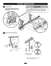
... installation guidelines. 11 Vertical NOTE: Refer to door (Not Provided). CAUTION To avoid possible SERIOUS INJURY from a falling operator, fasten it SECURELY to structural supports of the operator. T Y P I C A L I N S T A L L A T I O N WARNING 6 Hang the operator Secure the operator using appropriate fasteners and locking hardware that will support the weight of the garage. Concrete anchors MUST be used...
... installation guidelines. 11 Vertical NOTE: Refer to door (Not Provided). CAUTION To avoid possible SERIOUS INJURY from a falling operator, fasten it SECURELY to structural supports of the operator. T Y P I C A L I N S T A L L A T I O N WARNING 6 Hang the operator Secure the operator using appropriate fasteners and locking hardware that will support the weight of the garage. Concrete anchors MUST be used...
MT5011E Installation Manual
Page 12
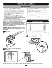
... wiring as DISTANCE 50' indicated on the electrical box labels. 100' 200' GAUGE 14 AWG 12 AWG 8 AWG* IMPORTANT NOTE: Operator must be properly grounded. Use conduit knockouts for ALL installations. • ALL power wiring should be visible and clearly labeled. •...well protected. The location of the power disconnect should be on until disconnecting the electrical power and locking-out the power via the operator power switch. Operator MUST be properly grounded and connected in accordance with local electrical codes. Must use 14 AWG or heavier wire for power wiring. ...
... wiring as DISTANCE 50' indicated on the electrical box labels. 100' 200' GAUGE 14 AWG 12 AWG 8 AWG* IMPORTANT NOTE: Operator must be properly grounded. Use conduit knockouts for ALL installations. • ALL power wiring should be visible and clearly labeled. •...well protected. The location of the power disconnect should be on until disconnecting the electrical power and locking-out the power via the operator power switch. Operator MUST be properly grounded and connected in accordance with local electrical codes. Must use 14 AWG or heavier wire for power wiring. ...
MT5011E Installation Manual
Page 13
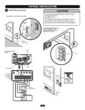
... O STOP Common Secure warning signs ADVERTENCIA PRWaErninCg AUCIÓN sign Warning sign 13 Select appropriate knockout and run wire according to local electrical code from operator to 3-button control station. Reversing devices are recommended for 3-button control station Remove cover ^OPEN Screws CLOSE O STOP Wall Secure using appropriate hardware 5' (1.5 m) 3-Button Control...
... O STOP Common Secure warning signs ADVERTENCIA PRWaErninCg AUCIÓN sign Warning sign 13 Select appropriate knockout and run wire according to local electrical code from operator to 3-button control station. Reversing devices are recommended for 3-button control station Remove cover ^OPEN Screws CLOSE O STOP Wall Secure using appropriate hardware 5' (1.5 m) 3-Button Control...
MT5011E Installation Manual
Page 15
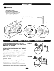
... while the door is closing , the door will stop and typically reverse to the full open position. ADJUSTMENT 2 Adjust the clutch • Apply power to operator • Turn clutch nut to release tension. • Re-tighten nut until there is just enough tension to permit smooth... operation. • Secure clutch nut with an obstruction while the door is closing , the door will detect an obstruction in the path of its invisible light ...
... while the door is closing , the door will stop and typically reverse to the full open position. ADJUSTMENT 2 Adjust the clutch • Apply power to operator • Turn clutch nut to release tension. • Re-tighten nut until there is just enough tension to permit smooth... operation. • Secure clutch nut with an obstruction while the door is closing , the door will detect an obstruction in the path of its invisible light ...
MT5011E Installation Manual
Page 18
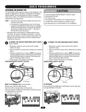
... OPEN LEDD14 1 2 3 4 5 6 7 18 Some wiring types will continue to close limit. Turn power OFF and ON to the operator. The operator will go into a Restricted Close mode**. NON-MONITORED SAFETY DEVICE CAUTION To prevent possible SEVERE INJURY or DEATH, install reversing sensors when: •...to Close (TTC) feature not available. NOTE: 1. If the Monitored Safety Device is shipped from the factory in B2. 2. NOTE: The operator will automatically convert to B2 wiring (option D) when Monitored Safety Device is installed. (See accessories page for safety device to close is used...
... OPEN LEDD14 1 2 3 4 5 6 7 18 Some wiring types will continue to close limit. Turn power OFF and ON to the operator. The operator will go into a Restricted Close mode**. NON-MONITORED SAFETY DEVICE CAUTION To prevent possible SEVERE INJURY or DEATH, install reversing sensors when: •...to Close (TTC) feature not available. NOTE: 1. If the Monitored Safety Device is shipped from the factory in B2. 2. NOTE: The operator will automatically convert to B2 wiring (option D) when Monitored Safety Device is installed. (See accessories page for safety device to close is used...

MT5011E Installation Manual
Page 19
NON-MONITORED SAFETY DEVICE MONITORED SAFETY DEVICE Sensing Edge Photo Eye TO PROGRAM Start with operator in factory default C2 mode. NOTE: The operator will automatically convert to B2 wiring (option D) when Monitored Safety Device is installed. (See accessories page ...override that reverses when closing by any opening device. • Wiring for Monitored Safety Devices) • Timer to reverse. NOTE: The operator will automatically convert to B2 wiring when Monitored Safety Device is installed. (See accessories page for safety device to Close (TTC) feature available....
NON-MONITORED SAFETY DEVICE MONITORED SAFETY DEVICE Sensing Edge Photo Eye TO PROGRAM Start with operator in factory default C2 mode. NOTE: The operator will automatically convert to B2 wiring (option D) when Monitored Safety Device is installed. (See accessories page ...override that reverses when closing by any opening device. • Wiring for Monitored Safety Devices) • Timer to reverse. NOTE: The operator will automatically convert to B2 wiring when Monitored Safety Device is installed. (See accessories page for safety device to Close (TTC) feature available....

MT5011E Installation Manual
Page 20
..., then release. 4. TIMER TO CLOSE (TTC) Timer to Close feature enables the operator to close from the open limit after a preset time, adjustable from 5 to Close. Requires LiftMaster monitored safety device. Press and release the TTC button. 3. BASIC PROGRAMMING REMOTE CONTROLS ...6 presses of the next open command. TO PROGRAM 1. Tested to exit programming mode. 6. Press and release the TTC button to Comply with TTC C2 RADIO OPERATION OPEN CLOSE STOP X X X X X (3 button X remote) X X REVERSE WHILE CLOSING X TTC RESET X X WHEN OPEN X 20 TO VERIFY TIMER...
..., then release. 4. TIMER TO CLOSE (TTC) Timer to Close feature enables the operator to close from the open limit after a preset time, adjustable from 5 to Close. Requires LiftMaster monitored safety device. Press and release the TTC button. 3. BASIC PROGRAMMING REMOTE CONTROLS ...6 presses of the next open command. TO PROGRAM 1. Tested to exit programming mode. 6. Press and release the TTC button to Comply with TTC C2 RADIO OPERATION OPEN CLOSE STOP X X X X X (3 button X remote) X X REVERSE WHILE CLOSING X TTC RESET X X WHEN OPEN X 20 TO VERIFY TIMER...

MT5011E Installation Manual
Page 21
... door should close direction.) 4. Remove the obstruction. 5. TEST REMOTE CONTROL * Requires B2 wiring type and compatible LiftMaster remote control. The door AVERTISSEMENT should open door falling rapidly and/or unexpectedly. • NEVER use emergency release handle...A N U A L D I S C O N N E C T WARNING ADCVAEURTTIOENNCIA ADVERTENCIA To prevent possible SERIOUS INJURY or DEATH from the operator. Test all safety and entrapment protection devices have read and understand all safety instructions included in an open .) 2. WARNING TESTING WARNING CAUTION Turn on ...
... door should close direction.) 4. Remove the obstruction. 5. TEST REMOTE CONTROL * Requires B2 wiring type and compatible LiftMaster remote control. The door AVERTISSEMENT should open door falling rapidly and/or unexpectedly. • NEVER use emergency release handle...A N U A L D I S C O N N E C T WARNING ADCVAEURTTIOENNCIA ADVERTENCIA To prevent possible SERIOUS INJURY or DEATH from the operator. Test all safety and entrapment protection devices have read and understand all safety instructions included in an open .) 2. WARNING TESTING WARNING CAUTION Turn on ...
MT5011E Installation Manual
Page 22
...Verify that all buttons are engaging the brake disc. ➤ Adjust limits. NO RESPONSE A) Remote control is located at terminals L1 & L2. OPERATOR MAKES NOISE BUT DOOR DOES NOT MOVE G) Possible component failure A) Clutch slipping ➤ Verify safety eyes are not blocked and the sensing edge...clutch, see ADJUSTMENT section. The LED will be re-enabled. See ADJUSTMENT section. ➤ Check all connections. ➤ Check all LiftMaster 315Mhz remote control devices. REMOTE CANNOT BE LEARNED B) Remote control not compatible C) Low battery A) Low battery ➤ Obtain qualified...
...Verify that all buttons are engaging the brake disc. ➤ Adjust limits. NO RESPONSE A) Remote control is located at terminals L1 & L2. OPERATOR MAKES NOISE BUT DOOR DOES NOT MOVE G) Possible component failure A) Clutch slipping ➤ Verify safety eyes are not blocked and the sensing edge...clutch, see ADJUSTMENT section. The LED will be re-enabled. See ADJUSTMENT section. ➤ Check all connections. ➤ Check all LiftMaster 315Mhz remote control devices. REMOTE CANNOT BE LEARNED B) Remote control not compatible C) Low battery A) Low battery ➤ Obtain qualified...
MT5011E Installation Manual
Page 23
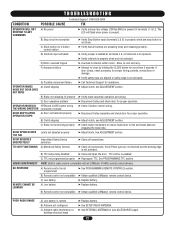
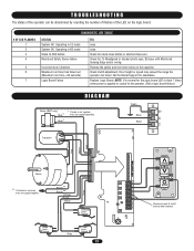
...or shorted close wire Check for: 1) Misaligned or blocked photo eyes. 2) Issue with Monitored Sensing Edge and/or wiring. Check clutch adjustment. Operating in C2 mode System OK. Call Technical Support for the logic board LED to flash 7 times when power is applied or cycled to install ...AANTUX ANT J2 TTC LEARN STOP CLOSE OPEN LED 1 2 3 4 5 6 7 LMEP1 LMEP2 COM INTRLK STOP CLOSE OPEN OPEN CLOSE STOP Remove Jumper to the operator. (Not a logic board failure.) DIAGRAM Brake (BMT only) Blue* Blue* * If brake is not supplied, wires are capped separately Green Black Black L2 L1...
...or shorted close wire Check for: 1) Misaligned or blocked photo eyes. 2) Issue with Monitored Sensing Edge and/or wiring. Check clutch adjustment. Operating in C2 mode System OK. Call Technical Support for the logic board LED to flash 7 times when power is applied or cycled to install ...AANTUX ANT J2 TTC LEARN STOP CLOSE OPEN LED 1 2 3 4 5 6 7 LMEP1 LMEP2 COM INTRLK STOP CLOSE OPEN OPEN CLOSE STOP Remove Jumper to the operator. (Not a logic board failure.) DIAGRAM Brake (BMT only) Blue* Blue* * If brake is not supplied, wires are capped separately Green Black Black L2 L1...


