
GT- Logic 4 Installation Manual
Page 1
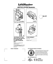
... to locate a professional installing dealer in C2 operating mode. Visit www.liftmaster.com to set number of cycles/months is reached or when the operator requires immediate service. The Logic 4 operator incorporates a self-diagnostic feature built into the ...(MAS) Maintenance Alert System LED. Operators are shipped in your area. An LED on Board INSTALLATION MANUAL H, J, AND HJ T AND APT L 4 ogic L3 GH...
... to locate a professional installing dealer in C2 operating mode. Visit www.liftmaster.com to set number of cycles/months is reached or when the operator requires immediate service. The Logic 4 operator incorporates a self-diagnostic feature built into the ...(MAS) Maintenance Alert System LED. Operators are shipped in your area. An LED on Board INSTALLATION MANUAL H, J, AND HJ T AND APT L 4 ogic L3 GH...

GT- Logic 4 Installation Manual
Page 2
... Sensors (Provided 21 Mount the Photoelectric Sensors (Provided 22 Wire the LiftMaster Monitored Entrapment Protection (LMEP) Devices 22 ADJUSTMENT 23-24 Limit Adjustment 23 Clutch Adjustment (Belt Drive Model Operators 24 TESTING 25 MANUAL RELEASE 26-27 Emergency Disconnect System Model GT ...and T 26 Emergency Disconnect System Model APT 26 Emergency Disconnect System Model H, GH, J, and HJ 27 PROGRAMMING 28-35 Introduction ...
... Sensors (Provided 21 Mount the Photoelectric Sensors (Provided 22 Wire the LiftMaster Monitored Entrapment Protection (LMEP) Devices 22 ADJUSTMENT 23-24 Limit Adjustment 23 Clutch Adjustment (Belt Drive Model Operators 24 TESTING 25 MANUAL RELEASE 26-27 Emergency Disconnect System Model GT ...and T 26 Emergency Disconnect System Model APT 26 Emergency Disconnect System Model H, GH, J, and HJ 27 PROGRAMMING 28-35 Introduction ...

GT- Logic 4 Installation Manual
Page 3
...contact with the cautionary AVERTISSEMENT statements that accompany it will alert you to the possibility of damage to your commercial door and WARNING gate operator unless you do so. 7. ADVERTENCIA 12. WARNING • DO NOT attempt repair or service of door. WARNING When you see .... Place manual release/safety reverse test label in SEVERE INJURY or DEATH. 3. Upon completion of the door. 9. Read the warnings carefully. Install door operator 8 feet (2.44 m) or more above floor. Install control station: • within sight of the door. • out of reach of children...
...contact with the cautionary AVERTISSEMENT statements that accompany it will alert you to the possibility of damage to your commercial door and WARNING gate operator unless you do so. 7. ADVERTENCIA 12. WARNING • DO NOT attempt repair or service of door. WARNING When you see .... Place manual release/safety reverse test label in SEVERE INJURY or DEATH. 3. Upon completion of the door. 9. Read the warnings carefully. Install door operator 8 feet (2.44 m) or more above floor. Install control station: • within sight of the door. • out of reach of children...

GT- Logic 4 Installation Manual
Page 4
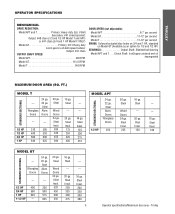
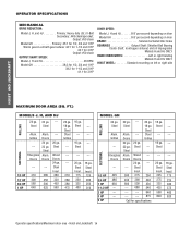
... (all components were provided. See page 29 for sensing device to reverse and auxiliary devices to 24 feet. ENTRAPMENT PROTECTION: LiftMaster Monitored Entrapment Protection (LMEP) Photoelectric Sensors (CPS-U Through beam used to the bottom edge of door. Safety Edge (Optional...adjustable screw type cams. Adjustable to open and close with LED Trolley drive chain: #48 for 1/3 and 1/2 HP, #41 for emergency manual door operation. OPERATOR SPECIFICATIONS MOTOR TYPE Continuous duty HORSEPOWER: Model APT 1/2 HP Model GT 1/2, 3/4, 1 and 1-1/2 HP Model T 1/3, 1/2, 3/4 and 1 HP ...
... (all components were provided. See page 29 for sensing device to reverse and auxiliary devices to 24 feet. ENTRAPMENT PROTECTION: LiftMaster Monitored Entrapment Protection (LMEP) Photoelectric Sensors (CPS-U Through beam used to the bottom edge of door. Safety Edge (Optional...adjustable screw type cams. Adjustable to open and close with LED Trolley drive chain: #48 for 1/3 and 1/2 HP, #41 for emergency manual door operation. OPERATOR SPECIFICATIONS MOTOR TYPE Continuous duty HORSEPOWER: Model APT 1/2 HP Model GT 1/2, 3/4, 1 and 1-1/2 HP Model T 1/3, 1/2, 3/4 and 1 HP ...
GT- Logic 4 Installation Manual
Page 5
... BEARINGS Output Shaft: Shielded ball bearing Model APT and T. . . .Clutch Shaft: IronCopper sintered and oil impregnated MAXIMUM DOOR AREA (SQ. TROLLEY OPERATOR SPECIFICATIONS MECHANICAL DRIVE REDUCTION: Model APT and T Primary: Heavy duty (5L) V-Belt Secondary: #41 chain/sprocket; FT.) STANDARD SECTIONAL MODEL T ...--- Steel Insul. 200 250 300 380 5 Operator specifications/Maximum door area - Steel Insul. 150 --- --- 16 ga. Steel --- 20 ga. Steel Alum. Steel Wood Doors 24 ga...
... BEARINGS Output Shaft: Shielded ball bearing Model APT and T. . . .Clutch Shaft: IronCopper sintered and oil impregnated MAXIMUM DOOR AREA (SQ. TROLLEY OPERATOR SPECIFICATIONS MECHANICAL DRIVE REDUCTION: Model APT and T Primary: Heavy duty (5L) V-Belt Secondary: #41 chain/sprocket; FT.) STANDARD SECTIONAL MODEL T ...--- Steel Insul. 200 250 300 380 5 Operator specifications/Maximum door area - Steel Insul. 150 --- --- 16 ga. Steel --- 20 ga. Steel Alum. Steel Wood Doors 24 ga...
GT- Logic 4 Installation Manual
Page 7
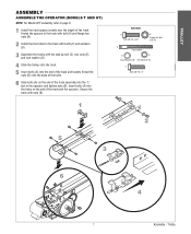
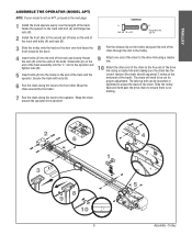
... the front idler to page 9. 1 Install the track spacers evenly over the length of the track and the operator. Insert bolts (A) into the "L" slot in the operator and tighten nuts (B). TROLLEY ASSEMBLY ASSEMBLE THE OPERATOR (MODELS T AND GT) NOTE: For Model APT assembly refer to the track with bolts (F) and washers (D). 3 Assemble the...
... the front idler to page 9. 1 Install the track spacers evenly over the length of the track and the operator. Insert bolts (A) into the "L" slot in the operator and tighten nuts (B). TROLLEY ASSEMBLY ASSEMBLE THE OPERATOR (MODELS T AND GT) NOTE: For Model APT assembly refer to the track with bolts (F) and washers (D). 3 Assemble the...
GT- Logic 4 Installation Manual
Page 8
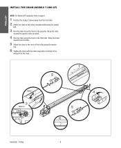
... sprocket. 4 Run the chain along the track to the operator. Trolley 8 Wrap the chain around the front idler. 5 Attach the chain to the front idler. TROLLEY INSTALL THE CHAIN (MODELS T AND GT) NOTE: For Model ...
... sprocket. 4 Run the chain along the track to the operator. Trolley 8 Wrap the chain around the front idler. 5 Attach the chain to the front idler. TROLLEY INSTALL THE CHAIN (MODELS T AND GT) NOTE: For Model ...
GT- Logic 4 Installation Manual
Page 9
.... 4 Insert bolts (A) into the holes on the end of the track. The take-up bolt can be cut for proper adjustment. Trolley TROLLEY ASSEMBLE THE OPERATOR (MODEL APT) NOTE: If your model is no binding. 7 Run the chain along the track to the next page. A Bolt 3/8"-16 x 3/4" B Flange Hex Nut 3/8"-16... link and making sure the chain has the correct tension (the chain should sag about 3 inches at the mid point of the track and the operator. Slide bolts (A) on the end of the track assembly into the "L" slot in the second set of holes on the end of the track). The...
.... 4 Insert bolts (A) into the holes on the end of the track. The take-up bolt can be cut for proper adjustment. Trolley TROLLEY ASSEMBLE THE OPERATOR (MODEL APT) NOTE: If your model is no binding. 7 Run the chain along the track to the next page. A Bolt 3/8"-16 x 3/4" B Flange Hex Nut 3/8"-16... link and making sure the chain has the correct tension (the chain should sag about 3 inches at the mid point of the track and the operator. Slide bolts (A) on the end of the track assembly into the "L" slot in the second set of holes on the end of the track). The...
GT- Logic 4 Installation Manual
Page 10
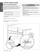
Typically, the operator may be required due to interfering structures or location of door stile / top section support. Mark the center of the door with appropriate hardware (not ... mark 4 inches above the highest point of travel. 3 Center the header bracket on torsion spring doors. TROLLEY TYPICAL INSTALLATION INSTALL THE HEADER BRACKET The trolley operator is generally mounted over drywall. • Concrete anchors MUST be used if mounting header bracket or 2x4 into masonry. • NEVER try to loosen, move...
Typically, the operator may be required due to interfering structures or location of door stile / top section support. Mark the center of the door with appropriate hardware (not ... mark 4 inches above the highest point of travel. 3 Center the header bracket on torsion spring doors. TROLLEY TYPICAL INSTALLATION INSTALL THE HEADER BRACKET The trolley operator is generally mounted over drywall. • Concrete anchors MUST be used if mounting header bracket or 2x4 into masonry. • NEVER try to loosen, move...
GT- Logic 4 Installation Manual
Page 11
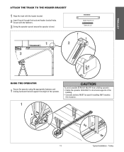
... possible SERIOUS INJURY from a falling operator: • Fasten the operator SECURELY to structural supports of the operator. Trolley TROLLEY ATTACH THE TRACK TO THE HEADER BRACKET 1 Align the track with the fasteners. 3 Swing the operator up and ensure the operator is level. Secure with the header... pin through the track and header bracket holes. HARDWARE Header Pivot Pin (1) Cotter pins (2) 1 2 3 WARNING HANG THE OPERATOR 1 Secure the operator using the appropriate fasteners and locking hardware that will support the weight of the building. • Concrete anchors MUST be used ...
... possible SERIOUS INJURY from a falling operator: • Fasten the operator SECURELY to structural supports of the operator. Trolley TROLLEY ATTACH THE TRACK TO THE HEADER BRACKET 1 Align the track with the fasteners. 3 Swing the operator up and ensure the operator is level. Secure with the header... pin through the track and header bracket holes. HARDWARE Header Pivot Pin (1) Cotter pins (2) 1 2 3 WARNING HANG THE OPERATOR 1 Secure the operator using the appropriate fasteners and locking hardware that will support the weight of the building. • Concrete anchors MUST be used ...
GT- Logic 4 Installation Manual
Page 12
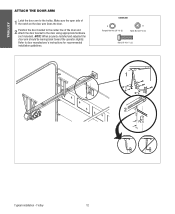
NOTE: When properly installed and adjusted the door arm should be leaning back toward the operator slightly. Refer to the door using appropriate hardware (not included). Make sure the open side of the notch on the door arm faces the door. 2 ...
NOTE: When properly installed and adjusted the door arm should be leaning back toward the operator slightly. Refer to the door using appropriate hardware (not included). Make sure the open side of the notch on the door arm faces the door. 2 ...

GT- Logic 4 Installation Manual
Page 13
...60Hz 8.5 11.2 13.6 16 230-1Ø, 60Hz 4.2 5.6 6.8 8 208/230-3Ø, 60Hz 3 3.1 4 6 460-3Ø, 60Hz 1.5 1.75 2 3 575-3Ø, 60Hz 1.3 1.4 1.6 1.8 Model GH Voltage-Phase 1/2 HP 3/4 HP 1 HP 1-1/2 HP 2 HP 3 HP 115-1Ø, 60Hz 11.2 13.6 16 20 - - 230-1Ø, 60Hz 5.6 6.8 8 10 - - 208/230-3Ø, ...and STOP, constant pressure to CLOSE, plus wiring for manual door operation Model HJ Includes both floor level disconnect systems stated above ENTRAPMENT PROTECTION: LiftMaster Monitored Entrapment Protection (LMEP) Photoelectric Sensors (CPS-U Through beam used ...
...60Hz 8.5 11.2 13.6 16 230-1Ø, 60Hz 4.2 5.6 6.8 8 208/230-3Ø, 60Hz 3 3.1 4 6 460-3Ø, 60Hz 1.5 1.75 2 3 575-3Ø, 60Hz 1.3 1.4 1.6 1.8 Model GH Voltage-Phase 1/2 HP 3/4 HP 1 HP 1-1/2 HP 2 HP 3 HP 115-1Ø, 60Hz 11.2 13.6 16 20 - - 230-1Ø, 60Hz 5.6 6.8 8 10 - - 208/230-3Ø, ...and STOP, constant pressure to CLOSE, plus wiring for manual door operation Model HJ Includes both floor level disconnect systems stated above ENTRAPMENT PROTECTION: LiftMaster Monitored Entrapment Protection (LMEP) Photoelectric Sensors (CPS-U Through beam used ...
GT- Logic 4 Installation Manual
Page 14
...--- --- 250 340 430 540 640 875 Call for 3 HP DOOR SPEED: Model J, H and HJ 8-9" per second depending on door Model GH 8-9" per second depending on door BRAKE Solenoid actuated disc brake BEARINGS Output Shaft: Shielded Ball Bearing Clutch Shaft: IronCopper sintered and oil impregnated Models...on left or right side HOIST AND JACKSHAFT MAXIMUM DOOR AREA (SQ. Steel Alum. Steel --- --- --- 16 ga. --Steel --- --- 20 ga. OPERATOR SPECIFICATIONS MECHANICAL DRIVE REDUCTION: Model J, H, and HJ Primary: Heavy duty (5L) V-Belt Secondary: #48 chain/sprocket; Steel Wood Doors 24 ga....
...--- --- 250 340 430 540 640 875 Call for 3 HP DOOR SPEED: Model J, H and HJ 8-9" per second depending on door Model GH 8-9" per second depending on door BRAKE Solenoid actuated disc brake BEARINGS Output Shaft: Shielded Ball Bearing Clutch Shaft: IronCopper sintered and oil impregnated Models...on left or right side HOIST AND JACKSHAFT MAXIMUM DOOR AREA (SQ. Steel Alum. Steel --- --- --- 16 ga. --Steel --- --- 20 ga. OPERATOR SPECIFICATIONS MECHANICAL DRIVE REDUCTION: Model J, H, and HJ Primary: Heavy duty (5L) V-Belt Secondary: #48 chain/sprocket; Steel Wood Doors 24 ga....
GT- Logic 4 Installation Manual
Page 15
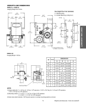
... Hand Chain Wheel Present with 1" x 1/4" key for 1/2 thru 1 HP operators, 1-3/16" x 5/16" key for 1-1/2 and 2 HP operators, 1-1/4" x 1/4" key for 3 HP operators. 2) Mounting centers: X = 4-3/4"; Y = 5-1/2" for 3 HP operators. 3) Hand chain wheel extends 1-5/8" beyond operator in vertical mounting position as shown. 15 Weights and dimensions - Y = 9-1/16...3-15/16 NOTES: 1) Output shaft with Models H and HJ ONLY 4.56" (11.58 cm) HOIST AND JACKSHAFT MODEL GH Hanging Weight: 140 lbs. X = 3-5/8"; Hoist and Jackshaft WEIGHTS AND DIMENSIONS MODELS J, H AND HJ Hanging Weight: 80-110...
... Hand Chain Wheel Present with 1" x 1/4" key for 1/2 thru 1 HP operators, 1-3/16" x 5/16" key for 1-1/2 and 2 HP operators, 1-1/4" x 1/4" key for 3 HP operators. 2) Mounting centers: X = 4-3/4"; Y = 5-1/2" for 3 HP operators. 3) Hand chain wheel extends 1-5/8" beyond operator in vertical mounting position as shown. 15 Weights and dimensions - Y = 9-1/16...3-15/16 NOTES: 1) Output shaft with Models H and HJ ONLY 4.56" (11.58 cm) HOIST AND JACKSHAFT MODEL GH Hanging Weight: 140 lbs. X = 3-5/8"; Hoist and Jackshaft WEIGHTS AND DIMENSIONS MODELS J, H AND HJ Hanging Weight: 80-110...

GT- Logic 4 Installation Manual
Page 16
... of the door jamb. An unbalanced door may be determined at the time of order. On models J, H, HJ and GH operators the drive sprocket can cause SERIOUS PERSONAL INJURY. • Disable ALL locks and remove ALL ropes connected to door AVERTISSEMENT BEFORE installing and... operating door operator to avoid entanglement. • Fasten the operator SECURELY to the side near the top of the AVERTISSEMENT building. • Concrete anchors MUST be fastened securely ...
... of the door jamb. An unbalanced door may be determined at the time of order. On models J, H, HJ and GH operators the drive sprocket can cause SERIOUS PERSONAL INJURY. • Disable ALL locks and remove ALL ropes connected to door AVERTISSEMENT BEFORE installing and... operating door operator to avoid entanglement. • Fasten the operator SECURELY to the side near the top of the AVERTISSEMENT building. • Concrete anchors MUST be fastened securely ...

GT- Logic 4 Installation Manual
Page 17
... the master link. 4 Align the door and the drive sprockets. MOUNTING 1 Place the door sprocket on the door shaft. 2 Place the operator drive sprocket on the appropriate side of the operator for your installation type. 3 Wrap the drive chain around the door sprocket and the drive sprocket then secure with the set...
... the master link. 4 Align the door and the drive sprockets. MOUNTING 1 Place the door sprocket on the door shaft. 2 Place the operator drive sprocket on the appropriate side of the operator for your installation type. 3 Wrap the drive chain around the door sprocket and the drive sprocket then secure with the set...
GT- Logic 4 Installation Manual
Page 18
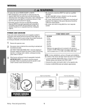
...MUST be made by a qualified individual. • DO NOT install ANY wiring or attempt to properly ground the operator could result in the wrong direction. IMPORTANT NOTE: This operator must be properly grounded. When a larger wire gauge is 12 AWG. Locate the MOTOR DIRECTION jumper on the ...Use conduit knockouts for power wiring. ON THREE PHASE MACHINES ONLY: Incorrect phasing of the motor and logic board may be connected to the operator's terminal is required, the wire must be gauged down to rotate in electric shock and serious injury. NOTE: In some installations, such ...
...MUST be made by a qualified individual. • DO NOT install ANY wiring or attempt to properly ground the operator could result in the wrong direction. IMPORTANT NOTE: This operator must be properly grounded. When a larger wire gauge is 12 AWG. Locate the MOTOR DIRECTION jumper on the ...Use conduit knockouts for power wiring. ON THREE PHASE MACHINES ONLY: Incorrect phasing of the motor and logic board may be connected to the operator's terminal is required, the wire must be gauged down to rotate in electric shock and serious injury. NOTE: In some installations, such ...
GT- Logic 4 Installation Manual
Page 19
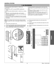
...: • Install door control within sight of door, out of reach of children at any Time Without Prior Warning Do Not Let Children Operate the Door or Play in the Door Area Keep Door in contact with door control push buttons or remote controls. • Activate door ONLY... properly adjusted and there are no obstructions to door travel. • ALWAYS keep door in sight until completely closed. NEVER permit anyone to the operator. Control station AVERTISSEMENT Connect wires to the control station and replace the control 4 station cover. 2 Fasten the control station to back page for...
...: • Install door control within sight of door, out of reach of children at any Time Without Prior Warning Do Not Let Children Operate the Door or Play in the Door Area Keep Door in contact with door control push buttons or remote controls. • Activate door ONLY... properly adjusted and there are no obstructions to door travel. • ALWAYS keep door in sight until completely closed. NEVER permit anyone to the operator. Control station AVERTISSEMENT Connect wires to the control station and replace the control 4 station cover. 2 Fasten the control station to back page for...
GT- Logic 4 Installation Manual
Page 20
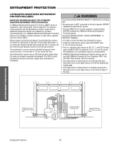
... or more than 6" (15 cm) aboAve VtheEfloRor.TISSEMENT • This is properly connected and aligned. above the floor. Use with LiftMaster Commercial Door Operators ONLY. InInvviissiibblleeLLigighht tBeBaemam PrPotreoctteiocntiAorneaArea PhSoafteoteylRecevtreircsiSngensor 6"S(e1n5socrm) max. If a LiftMaster Monitored Entrapment Protection device is required for purchase (see accessories). WARNING To prevent possible SERIOUS INJURY or DEATH from the...
... or more than 6" (15 cm) aboAve VtheEfloRor.TISSEMENT • This is properly connected and aligned. above the floor. Use with LiftMaster Commercial Door Operators ONLY. InInvviissiibblleeLLigighht tBeBaemam PrPotreoctteiocntiAorneaArea PhSoafteoteylRecevtreircsiSngensor 6"S(e1n5socrm) max. If a LiftMaster Monitored Entrapment Protection device is required for purchase (see accessories). WARNING To prevent possible SERIOUS INJURY or DEATH from the...
GT- Logic 4 Installation Manual
Page 22
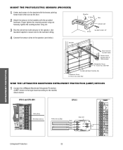
... sensors to the models shown below ). above floor WIRE THE LIFTMASTER MONITORED ENTRAPMENT PROTECTION (LMEP) DEVICES 1 Connect the LiftMaster Monitored Entrapment Protection (LMEP) device to the logic board according to the operator. Finger tighten the receiving sensor wing nut. above floor Invisible ... with the lenses pointing toward each other across the door. 2 Attach the sensors to the brackets with insulated staples Connect wire to Operator (refer to following page) Photoelectric Sensor 6" (15 cm) max. Use insulated staples to secure wire to the wall and ceiling....
... sensors to the models shown below ). above floor WIRE THE LIFTMASTER MONITORED ENTRAPMENT PROTECTION (LMEP) DEVICES 1 Connect the LiftMaster Monitored Entrapment Protection (LMEP) device to the logic board according to the operator. Finger tighten the receiving sensor wing nut. above floor Invisible ... with the lenses pointing toward each other across the door. 2 Attach the sensors to the brackets with insulated staples Connect wire to Operator (refer to following page) Photoelectric Sensor 6" (15 cm) max. Use insulated staples to secure wire to the wall and ceiling....


