Dial Code LC and VF Series Manual
Page 4
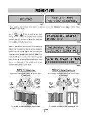
.... Entry 1 - RESIDENT USE WELCOME Use Keys To View Directory (fig a.) (fig b.) When operating, the Telephone Entry System will open the vehicular entrance gate. Door or Pedestrian Gate By pressing or dialing the number "5" on their digital or rotary phone, OR OR The resident will display the talk time as shown in (fig c.) The names are listed in (fig e.) If the resident wants to allow access...
.... Entry 1 - RESIDENT USE WELCOME Use Keys To View Directory (fig a.) (fig b.) When operating, the Telephone Entry System will open the vehicular entrance gate. Door or Pedestrian Gate By pressing or dialing the number "5" on their digital or rotary phone, OR OR The resident will display the talk time as shown in (fig c.) The names are listed in (fig e.) If the resident wants to allow access...
Dial Code LC and VF Series Manual
Page 10
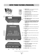
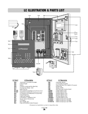
... (RJ11) - Connects to the program mode. 10 EXIT KEY - Used for RS485 devices. 3 POWER ON/OFF SWITCH 4 CARD RELEASE BUTTONS - Press this key to go back to change without notice. LC/VF Page 9 Erases information screens no longer needed. 10 7 8 9 14 12 ENTER KEY - Connects to desired position within screens. 9 PROGRAM KEY - Displays information and instructions, two lines at a time. 8 DIRECTION KEYS - Move cursor to surge suppressor terminal board. 17 INPUT...
... (RJ11) - Connects to the program mode. 10 EXIT KEY - Used for RS485 devices. 3 POWER ON/OFF SWITCH 4 CARD RELEASE BUTTONS - Press this key to go back to change without notice. LC/VF Page 9 Erases information screens no longer needed. 10 7 8 9 14 12 ENTER KEY - Connects to desired position within screens. 9 PROGRAM KEY - Displays information and instructions, two lines at a time. 8 DIRECTION KEYS - Move cursor to surge suppressor terminal board. 17 INPUT...
Dial Code LC and VF Series Manual
Page 13
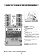
... postal lock access to the owners manual for proper grounding instructions. Activates gate relay using gate strike time. 8 CHASSIS GROUND: Entry Phone MUST be connected to the ground rod. Refer to "Grounding the Unit" and " Earth Ground Rod Installation" sections. 9 POWER LED: Indicates Phone system has 12 Vac power. 10 GATE RELAY LED: Indicates gate relay is activated. 11 DOOR RELAY LED: Indicates door relay is not grounded, lightning damage will occur. The provided "chassis ground" wire must...
... postal lock access to the owners manual for proper grounding instructions. Activates gate relay using gate strike time. 8 CHASSIS GROUND: Entry Phone MUST be connected to the ground rod. Refer to "Grounding the Unit" and " Earth Ground Rod Installation" sections. 9 POWER LED: Indicates Phone system has 12 Vac power. 10 GATE RELAY LED: Indicates gate relay is activated. 11 DOOR RELAY LED: Indicates door relay is not grounded, lightning damage will occur. The provided "chassis ground" wire must...
Dial Code LC and VF Series Manual
Page 16
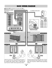
... MANDATORY that this unit is properly d The pro i Entry 1 Gate Relay Terminal Connection Vehicular Gate Removable Screw Terminal Connectors for the phone system ONLY! The door relay will be activated by either pressing 9 on the resident's phone, Door 7-day timer or ElitePro remote programming software. Entry 2 Door Relay Terminal Connection Pedestrian Gate Maglock Conduit Conduit Master Gate Operator (Strike Open Input) Access Door Solenoid OR OR Entry Door Maglock Dial Dial Connect two wires to the secondary gate or door. The gate relay will be activated...
... MANDATORY that this unit is properly d The pro i Entry 1 Gate Relay Terminal Connection Vehicular Gate Removable Screw Terminal Connectors for the phone system ONLY! The door relay will be activated by either pressing 9 on the resident's phone, Door 7-day timer or ElitePro remote programming software. Entry 2 Door Relay Terminal Connection Pedestrian Gate Maglock Conduit Conduit Master Gate Operator (Strike Open Input) Access Door Solenoid OR OR Entry Door Maglock Dial Dial Connect two wires to the secondary gate or door. The gate relay will be activated...
Dial Code LC and VF Series Manual
Page 17
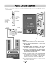
... switch as the nuts are used only when postal access to the owners manual for a duration according to the programmed "Gate Strike Time". 6 Test operation by application to the ground rod. The postal lock mechanism must be obtained by activating the lock. Please refer to your local post office. Note that full extension of Telephone Entry System Postal Lock Postal Lock Switch Wires (2) Side View Postal Lock Switch Assembly Switch Assembly POWER GATE Mounting Holes RELAY DOOR RELAY...
... switch as the nuts are used only when postal access to the owners manual for a duration according to the programmed "Gate Strike Time". 6 Test operation by application to the ground rod. The postal lock mechanism must be obtained by activating the lock. Please refer to your local post office. Note that full extension of Telephone Entry System Postal Lock Postal Lock Switch Wires (2) Side View Postal Lock Switch Assembly Switch Assembly POWER GATE Mounting Holes RELAY DOOR RELAY...

Dial Code LC and VF Series Manual
Page 30
... current day of your choice. DATE AND TIME Use the 1 key to set the date and time, and to program gates and doors to be opened or closed whenever specified. The key will complete the date and time entry. (fig e.) SELECT PROG MODE: (C)Clock/Timer (fig a.) PROG CLOCK/TIMER (1)Date & Time PROG CLOCK/TIMER (2)Gate Timer PROG CLOCK/TIMER (3)Door Timer (fig b.) DATE>02-11-2000 Time>07:31am p=pm (fig c.) Today Is THURSDAY...
... current day of your choice. DATE AND TIME Use the 1 key to set the date and time, and to program gates and doors to be opened or closed whenever specified. The key will complete the date and time entry. (fig e.) SELECT PROG MODE: (C)Clock/Timer (fig a.) PROG CLOCK/TIMER (1)Date & Time PROG CLOCK/TIMER (2)Gate Timer PROG CLOCK/TIMER (3)Door Timer (fig b.) DATE>02-11-2000 Time>07:31am p=pm (fig c.) Today Is THURSDAY...
Dial Code LC and VF Series Manual
Page 37
No Memory Card Key for Internal / External Lock LCD Display Kit for Keypad Light Phone Control Board (Inside Processor) T033 T035 T036 T037 T044 T060 T25MEM T50MEM T150MEM T250MEM T500MEM T1000MEM RFCARD4K RFCARD8K RFCARD16K LCD Display Window LC External Box Assembly Heater Pad Option (Pre-Installed in Processor) Keypad Light Speaker 4 OHM Dial Code Surge Protection Board 25 Name Memory Card 50 Name Memory Card 150 Name...
No Memory Card Key for Internal / External Lock LCD Display Kit for Keypad Light Phone Control Board (Inside Processor) T033 T035 T036 T037 T044 T060 T25MEM T50MEM T150MEM T250MEM T500MEM T1000MEM RFCARD4K RFCARD8K RFCARD16K LCD Display Window LC External Box Assembly Heater Pad Option (Pre-Installed in Processor) Keypad Light Speaker 4 OHM Dial Code Surge Protection Board 25 Name Memory Card 50 Name Memory Card 150 Name...
Dial Code LC and VF Series Manual
Page 38
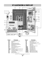
... Box Connection Kit (Surge Protection Terminal) Vacuum Florescent Display VF Complete Internal Metal Box (Processor Box) Programming Keys Postal Lock Assembly VFD Processor - No Memory Card T029 T031 T032 T034 T036 T037 T044 T060 T25MEM T50MEM T150MEM T250MEM T500MEM T1000MEM RFCARD4K RFCARD8K RFCARD16K Key for Internal / External Lock Kit for Keypad Light Phone Control Board (Inside Processor) VF External Box Assembly Heater Pad Option (Pre-Installed in Processor) Keypad Light Speaker 4 OHM Dial Code...
... Box Connection Kit (Surge Protection Terminal) Vacuum Florescent Display VF Complete Internal Metal Box (Processor Box) Programming Keys Postal Lock Assembly VFD Processor - No Memory Card T029 T031 T032 T034 T036 T037 T044 T060 T25MEM T50MEM T150MEM T250MEM T500MEM T1000MEM RFCARD4K RFCARD8K RFCARD16K Key for Internal / External Lock Kit for Keypad Light Phone Control Board (Inside Processor) VF External Box Assembly Heater Pad Option (Pre-Installed in Processor) Keypad Light Speaker 4 OHM Dial Code...

Dial Code Controller Manual
Page 4
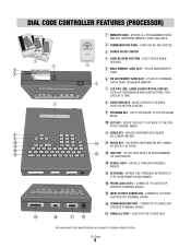
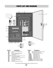
DIAL CODE CONTROLLER FEATURES (INSIDE) Mounting Holes (4) Processor Key Release / Lock LC Display Memory Card Memory Card Slot Memory Card Release Buttons Processor Power Switch Processor Unit Dialing Keys Programming Keys Parallel Port POWER GATE RELAY DOOR RELAY Surge Suppressor Terminal Board Stainless Steel Door Key Lock All components and specifications are subject to change without notice. CU Page 3
DIAL CODE CONTROLLER FEATURES (INSIDE) Mounting Holes (4) Processor Key Release / Lock LC Display Memory Card Memory Card Slot Memory Card Release Buttons Processor Power Switch Processor Unit Dialing Keys Programming Keys Parallel Port POWER GATE RELAY DOOR RELAY Surge Suppressor Terminal Board Stainless Steel Door Key Lock All components and specifications are subject to change without notice. CU Page 3
Dial Code Controller Manual
Page 6
... specifications are subject to change without notice. HOLDS RF COMMUNICATOR CARD OR BACKUP MEMORY. 7 LCD TWO LINE, LARGE LIQUID CRYSTAL DISPLAY DISPLAYS INFORMATION AND INSTRUCTIONS, TWO LINES AT A TIME. 7 8 DIRECTION KEYS - SETS PROCESSOR TO THE PROGRAM MODE. 10 EXIT KEY - WORKS LIKE STANDARD KEYBOARD TO TYPE IN INFORMATION AND NAMES. 16 PHONE JACK (RJ11) - CONNECTS TO SURGE SUPPRESSOR TERMINAL BOARD. 18 COMMUNICATION PORT - STORES ALL PROGRAMMED INFORMATION...
... specifications are subject to change without notice. HOLDS RF COMMUNICATOR CARD OR BACKUP MEMORY. 7 LCD TWO LINE, LARGE LIQUID CRYSTAL DISPLAY DISPLAYS INFORMATION AND INSTRUCTIONS, TWO LINES AT A TIME. 7 8 DIRECTION KEYS - SETS PROCESSOR TO THE PROGRAM MODE. 10 EXIT KEY - WORKS LIKE STANDARD KEYBOARD TO TYPE IN INFORMATION AND NAMES. 16 PHONE JACK (RJ11) - CONNECTS TO SURGE SUPPRESSOR TERMINAL BOARD. 18 COMMUNICATION PORT - STORES ALL PROGRAMMED INFORMATION...

Dial Code Controller Manual
Page 8
... control access through main vehicular gate. 6 VCR RELAY: For use with Time Lapse VCR. Activates gate relay using gate strike time. 8 CHASSIS GROUND: Entry Phone MUST be connected to pedestrian gate or door. eliteentryphone.com MADE IN USA 9 POWER GATE 10 RELAY DOOR 11 RELAY Removable Screw Terminal Connectors for proper grounding instructions. CU Page 7 If unit is properly grounded. Please refer to the owners manual for Easy Wiring. 1 TELEPHONE LINE: Tip and Ring Connection. 2 POWER IN: 12 VAC transformer...
... control access through main vehicular gate. 6 VCR RELAY: For use with Time Lapse VCR. Activates gate relay using gate strike time. 8 CHASSIS GROUND: Entry Phone MUST be connected to pedestrian gate or door. eliteentryphone.com MADE IN USA 9 POWER GATE 10 RELAY DOOR 11 RELAY Removable Screw Terminal Connectors for proper grounding instructions. CU Page 7 If unit is properly grounded. Please refer to the owners manual for Easy Wiring. 1 TELEPHONE LINE: Tip and Ring Connection. 2 POWER IN: 12 VAC transformer...

Dial Code Controller Manual
Page 11
... 20 AWG 225 Ft 18 AWG 350 Ft 16 AWG 560 Ft 12V AC/DC POWER IN It is MANDATORY that this unit is properly d d The provid Entry 1 Gate Relay Terminal Connection Vehicular Gate Removable Screw Terminal Connectors for the phone system ONLY! Entry 2 Door Relay Terminal Connection Pedestrian Gate Maglock Conduit Conduit Master Gate Operator (Strike Open Input) Access Door Solenoid OR OR Entry Door Maglock Connect two wires to the secondary gate or door.
... 20 AWG 225 Ft 18 AWG 350 Ft 16 AWG 560 Ft 12V AC/DC POWER IN It is MANDATORY that this unit is properly d d The provid Entry 1 Gate Relay Terminal Connection Vehicular Gate Removable Screw Terminal Connectors for the phone system ONLY! Entry 2 Door Relay Terminal Connection Pedestrian Gate Maglock Conduit Conduit Master Gate Operator (Strike Open Input) Access Door Solenoid OR OR Entry Door Maglock Connect two wires to the secondary gate or door.
Dial Code Controller Manual
Page 28
... and specifications are subject to change without notice. PARTS LIST AND DIAGRAM T010 T009 T011 T060 T020 T030 Memory Card Remo e Access RS-485 COMMUNICATOR CARD capacity Elite Entry Phone RS-485 Card T027 LC Processor TEL LINE RS 485 (1) RS 485 (2) RS 485 (3) 5 (4) TIP R NG (+) () GND (+) () GND (+) () GND (+) () GND 12V AC/DC POWER NPUT DOOR NO DOOR NC DOOR C GATE NO GATE NC GATE...
... and specifications are subject to change without notice. PARTS LIST AND DIAGRAM T010 T009 T011 T060 T020 T030 Memory Card Remo e Access RS-485 COMMUNICATOR CARD capacity Elite Entry Phone RS-485 Card T027 LC Processor TEL LINE RS 485 (1) RS 485 (2) RS 485 (3) 5 (4) TIP R NG (+) () GND (+) () GND (+) () GND (+) () GND 12V AC/DC POWER NPUT DOOR NO DOOR NC DOOR C GATE NO GATE NC GATE...
Dial Code LC Series Manual
Page 2
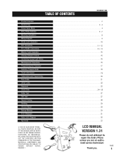
... 1999 Product Overview Resident Use Screen Saver Mode Entry Phone Features Mounting Installation Wiring Diagram Postal Lock Installation Port Connectors RF & RS485 Connections Memory Card Installation Viewing Software Version Connecting Keypad Light Wires Warnings and Precautions Programming the Processor Selecting Program Mode Tenant Information Transmitter/Card Programming Area Codes Utility Codes Password Clock Timer Strike Time Talk Time Report Printing Greeting Volume Adjust Backup Memory Error Messages Parts List & Diagram Approvals © 1997 BY ELITE ENTRY PHONE ALL RIGHTS RESERVED...
... 1999 Product Overview Resident Use Screen Saver Mode Entry Phone Features Mounting Installation Wiring Diagram Postal Lock Installation Port Connectors RF & RS485 Connections Memory Card Installation Viewing Software Version Connecting Keypad Light Wires Warnings and Precautions Programming the Processor Selecting Program Mode Tenant Information Transmitter/Card Programming Area Codes Utility Codes Password Clock Timer Strike Time Talk Time Report Printing Greeting Volume Adjust Backup Memory Error Messages Parts List & Diagram Approvals © 1997 BY ELITE ENTRY PHONE ALL RIGHTS RESERVED...

Dial Code LC Series Manual
Page 8
... future remote control and card access use. 23 24 25 26 27 26 INPUT/OUTPUT CONNECTOR - Erases information screens no longer needed. 21 EXIT KEY - Registers information into memory after it is typed. 28 24 PRINTER PARALLEL PORT - Press this key to go back to type in programming or user modes. 20 ERASE KEY - ENTRY PHONE FEATURES 13 POWER ON/OFF SWITCH 14 MEMORY CARD RELEASE BUTTONS...
... future remote control and card access use. 23 24 25 26 27 26 INPUT/OUTPUT CONNECTOR - Erases information screens no longer needed. 21 EXIT KEY - Registers information into memory after it is typed. 28 24 PRINTER PARALLEL PORT - Press this key to go back to type in programming or user modes. 20 ERASE KEY - ENTRY PHONE FEATURES 13 POWER ON/OFF SWITCH 14 MEMORY CARD RELEASE BUTTONS...

Dial Code LC Series Manual
Page 11
... speaker. Connect the two wires from the postal lock switch in the diagram. Note that full extension of the Entry Phone and remove the hole plug. Ensure that polarity or color coding is required. POSTAL LOCK INSTALLATION These parts are tightened to ensure switch activation when the bolt is extended. Installation: Open the front panel of the sliding bolt will activate the switch as the nuts are used only...
... speaker. Connect the two wires from the postal lock switch in the diagram. Note that full extension of the Entry Phone and remove the hole plug. Ensure that polarity or color coding is required. POSTAL LOCK INSTALLATION These parts are tightened to ensure switch activation when the bolt is extended. Installation: Open the front panel of the sliding bolt will activate the switch as the nuts are used only...

Dial Code LC Series Manual
Page 33
... Mobile Power Connection Kit (Includes: transformer and 15 pin connector) External Box Connection Kit (Includes: external mic, external speaker, & 15 pin connector) PART # T025 T026 T027 T029 T030 T031 T033 T035 T038 DESCRIPTION Programming Keys Postal Lock Assembly LCD Processor Key For Internal / External Lock LCD Display Kit For Keypad Light Window Display External Box Assy. (LC), (No Processor, Postal Lock or Memory Card) Stainless Steel Door (LC) All components and specifications are...
... Mobile Power Connection Kit (Includes: transformer and 15 pin connector) External Box Connection Kit (Includes: external mic, external speaker, & 15 pin connector) PART # T025 T026 T027 T029 T030 T031 T033 T035 T038 DESCRIPTION Programming Keys Postal Lock Assembly LCD Processor Key For Internal / External Lock LCD Display Kit For Keypad Light Window Display External Box Assy. (LC), (No Processor, Postal Lock or Memory Card) Stainless Steel Door (LC) All components and specifications are...
Dial Code VF Series Manual
Page 2
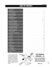
... 1999 Product Overview Resident Use Screen Saver Mode Entry Phone Features Mounting Installation Wiring Diagram Postal Lock Installation Port Connectors RF & RS485 Connections Memory Card Installation Viewing Software Version Connecting Keypad Light Wires Warnings and Precautions Programming the Processor Selecting Program Mode Tenant Information Transmitter/Card Programming Area Codes Utility Codes Password Clock Timer Strike Time Talk Time Report Printing Greeting Volume Adjust Backup Memory Error Messages Parts List & Diagram Approvals © 1997 BY ELITE ENTRY PHONE ALL RIGHTS RESERVED...
... 1999 Product Overview Resident Use Screen Saver Mode Entry Phone Features Mounting Installation Wiring Diagram Postal Lock Installation Port Connectors RF & RS485 Connections Memory Card Installation Viewing Software Version Connecting Keypad Light Wires Warnings and Precautions Programming the Processor Selecting Program Mode Tenant Information Transmitter/Card Programming Area Codes Utility Codes Password Clock Timer Strike Time Talk Time Report Printing Greeting Volume Adjust Backup Memory Error Messages Parts List & Diagram Approvals © 1997 BY ELITE ENTRY PHONE ALL RIGHTS RESERVED...

Dial Code VF Series Manual
Page 17
... codes & standards. Do not touch the terminals. STEP 2 Wire the black & white wires to rain, snow, or harsh weather conditions. The Entry Phone is only water resistant when the Stainless Steel Door is closed and locked. STEP 4 Plug in the hood should light with the black and white wires on . All five lights in the transformer. IF YOU ARE USING A SECOND TRANSFORMER TO POWER THE LIGHT: (Time...
... codes & standards. Do not touch the terminals. STEP 2 Wire the black & white wires to rain, snow, or harsh weather conditions. The Entry Phone is only water resistant when the Stainless Steel Door is closed and locked. STEP 4 Plug in the hood should light with the black and white wires on . All five lights in the transformer. IF YOU ARE USING A SECOND TRANSFORMER TO POWER THE LIGHT: (Time...

Dial Code VF Series Manual
Page 33
... T011 PART # T013 T014 T018 T025 T026 T028 T029 T031 T034 DESCRIPTION Mobile Power Connection Kit (Includes: transformer and 15 pin connector) External Box Connection Kit (Includes: external mic, external speaker, & 15 pin connector) Vacuum Florescent Display Programming Keys Postal Lock Assembly VFD Processor Key For Internal / External Lock Kit For Keypad Light External Box Assy. (VF) (No Processor, Postal Lock or Memory Card) All components and specifications are subject to change without...
... T011 PART # T013 T014 T018 T025 T026 T028 T029 T031 T034 DESCRIPTION Mobile Power Connection Kit (Includes: transformer and 15 pin connector) External Box Connection Kit (Includes: external mic, external speaker, & 15 pin connector) Vacuum Florescent Display Programming Keys Postal Lock Assembly VFD Processor Key For Internal / External Lock Kit For Keypad Light External Box Assy. (VF) (No Processor, Postal Lock or Memory Card) All components and specifications are subject to change without...


