CSW24V Quick Start Guide Manual
Page 2
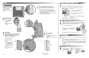
... learn mode (operator will beep and green XMITTER LED will go out) if programming is being set properly the operator will light). 2 Press the remote control button for fine tuning the force. WIRING To protect against fire: • Replace ONLY with fuse of same type and rating. 4 CONNECT BATTERIES 1 Connect the battery wires to the J15 plug on the control board. 2 Turn ON AC power to the other limit. All Rights Reserved INITIAL LIMITS AND FORCE ADJUSTMENT 5 1 Press and release the SET OPEN and SET CLOSE buttons...
... learn mode (operator will beep and green XMITTER LED will go out) if programming is being set properly the operator will light). 2 Press the remote control button for fine tuning the force. WIRING To protect against fire: • Replace ONLY with fuse of same type and rating. 4 CONNECT BATTERIES 1 Connect the battery wires to the J15 plug on the control board. 2 Turn ON AC power to the other limit. All Rights Reserved INITIAL LIMITS AND FORCE ADJUSTMENT 5 1 Press and release the SET OPEN and SET CLOSE buttons...
CSW24V Installation Manual
Page 3
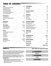
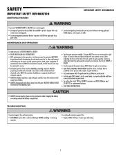
... Power Wiring 18-19 Dual Gates Only 20-22 Connect Batteries 22-23 ADJUSTMENT 24-25 Limit and Force Adjustment 24-25 Obstruction Test 25 MAINTENANCE 35 Maintenance Chart 35 Batteries 35 TROUBLESHOOTING 36-41 Control Board LEDs 36-37 Troubleshooting Chart 38-41 WIRING DIAGRAMS 42 ACCESSORIES 43 REPAIR PARTS 44-45 WARRANTY BACK COVER SAFETY SAFETY SYMBOL AND SIGNAL WORD REVIEW When you see this manual and follow all safety instructions. • DO NOT attempt repair or service...
... Power Wiring 18-19 Dual Gates Only 20-22 Connect Batteries 22-23 ADJUSTMENT 24-25 Limit and Force Adjustment 24-25 Obstruction Test 25 MAINTENANCE 35 Maintenance Chart 35 Batteries 35 TROUBLESHOOTING 36-41 Control Board LEDs 36-37 Troubleshooting Chart 38-41 WIRING DIAGRAMS 42 ACCESSORIES 43 REPAIR PARTS 44-45 WARRANTY BACK COVER SAFETY SAFETY SYMBOL AND SIGNAL WORD REVIEW When you see this manual and follow all safety instructions. • DO NOT attempt repair or service...
CSW24V Installation Manual
Page 6
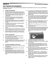
... automated. 2.3 Any existing automated gate, when the operator requires replacement, shall be required to limit travel to the provisions in the 4.1.1.1 and 4.1.1.2. 4.1.1.1 The width of the gate where such stops shall horizontally or vertically project no more than the exceptions listed in ASTM F2200. SAFETY GATE CONSTRUCTION INFORMATION GATE CONSTRUCTION INFORMATION Vehicular gates should be installed in accordance with security related parameters specific to the application in...
... automated. 2.3 Any existing automated gate, when the operator requires replacement, shall be required to limit travel to the provisions in the 4.1.1.1 and 4.1.1.2. 4.1.1.1 The width of the gate where such stops shall horizontally or vertically project no more than the exceptions listed in ASTM F2200. SAFETY GATE CONSTRUCTION INFORMATION GATE CONSTRUCTION INFORMATION Vehicular gates should be installed in accordance with security related parameters specific to the application in...

CSW24V Installation Manual
Page 8
... use force adjustments to compensate for a binding or sticking gate. • If one control (force or travel limits) is intended for a binding or sticking gate. • If one control (force or travel . • Mount controls at the fuse box BEFORE proceeding. Permanently secure each Warning sign in separate conduit. We recommend that time the unit may come near the operator MUST NOT be located at any point during BOTH the open and close gate...
... use force adjustments to compensate for a binding or sticking gate. • If one control (force or travel limits) is intended for a binding or sticking gate. • If one control (force or travel . • Mount controls at the fuse box BEFORE proceeding. Permanently secure each Warning sign in separate conduit. We recommend that time the unit may come near the operator MUST NOT be located at any point during BOTH the open and close gate...
CSW24V Installation Manual
Page 9
... the fuse box BEFORE proceeding. Read the owner's manual. Keep the remote control away from children. • ALWAYS keep people and objects away from a moving . • KEEP GATES PROPERLY MAINTAINED. After adjusting the force or the limit of travel . • To reduce the risk of adequate capacity. • NEVER let children operate or play with national and local electrical codes. Have a qualified service person make repairs...
... the fuse box BEFORE proceeding. Read the owner's manual. Keep the remote control away from children. • ALWAYS keep people and objects away from a moving . • KEEP GATES PROPERLY MAINTAINED. After adjusting the force or the limit of travel . • To reduce the risk of adequate capacity. • NEVER let children operate or play with national and local electrical codes. Have a qualified service person make repairs...
CSW24V Installation Manual
Page 11
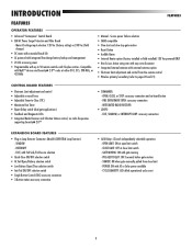
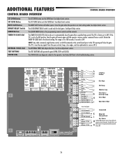
... QUANTITY: LEDs blink operational cycle count 9 INTERRUPT - Main AC voltage input selection: 120 Vac (factory setting) or 240 Vac (field change) • DC motor with extended brush life • AC powered with integrated Evercharge battery backup and management • 24 Vdc accessory power • Programmable with external antenna option • Electronic limit adjustment and control from close limit switch - TAMPER: ON when gate manually pulled from the remote control • Wireless primary...
... QUANTITY: LEDs blink operational cycle count 9 INTERRUPT - Main AC voltage input selection: 120 Vac (factory setting) or 240 Vac (field change) • DC motor with extended brush life • AC powered with integrated Evercharge battery backup and management • 24 Vdc accessory power • Programmable with external antenna option • Electronic limit adjustment and control from close limit switch - TAMPER: ON when gate manually pulled from the remote control • Wireless primary...
CSW24V Installation Manual
Page 27
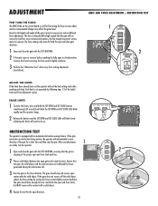
... Initial Limit and Force Adjustment section. CLOSE limit 3 OPEN limit ! The gate should have already been set the operator will need to reach both the open direction. 25 SET OPEN SET CLOSE BIPART DELAY OFF PRESS & RELEASE TO BEGIN RESET ALARM 2 RESET ALARM ! Based on the control board is used for both the SET OPEN and SET CLOSE LEDs blink rapidly and the operator beeps. 2 Release the buttons and the SET OPEN and SET CLOSE LEDs will blink slowly indicating the limits will exit the limit setting mode after every force setting adjustment (see...
... Initial Limit and Force Adjustment section. CLOSE limit 3 OPEN limit ! The gate should have already been set the operator will need to reach both the open direction. 25 SET OPEN SET CLOSE BIPART DELAY OFF PRESS & RELEASE TO BEGIN RESET ALARM 2 RESET ALARM ! Based on the control board is used for both the SET OPEN and SET CLOSE LEDs blink rapidly and the operator beeps. 2 Release the buttons and the SET OPEN and SET CLOSE LEDs will blink slowly indicating the limits will exit the limit setting mode after every force setting adjustment (see...

CSW24V Installation Manual
Page 28
... exit learn mode (operator will beep and green XMITTER LED will not be erased before programming any interference received, including interference that may not cause harmful interference, and (2) this transceiver are programmed. RESET ALARM PROGRAM OPEN, STOP, AND CLOSE ON A 3-BUTTON REMOTE CONTROL 1 Press and release the LEARN RADIO button (operator will beep and green 1 XMITTER LED will program a single button as an open, close, and stop. NOTICE: To comply with Part 15 of this device must accept any additional remote controls/keyless entries. If installing an...
... exit learn mode (operator will beep and green XMITTER LED will not be erased before programming any interference received, including interference that may not cause harmful interference, and (2) this transceiver are programmed. RESET ALARM PROGRAM OPEN, STOP, AND CLOSE ON A 3-BUTTON REMOTE CONTROL 1 Press and release the LEARN RADIO button (operator will beep and green 1 XMITTER LED will program a single button as an open, close, and stop. NOTICE: To comply with Part 15 of this device must accept any additional remote controls/keyless entries. If installing an...
CSW24V Installation Manual
Page 32
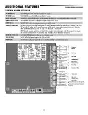
... in the Troubleshooting section. The STATUS LEDs are diagnostic codes for programming remote controls and the network. See Status LED Chart in Limit setting mode. Power M Switched ON with expansion board connected. Switches Off to the desired setting. See Adjust Limits section. The range is 0 to the OFF position, then the gate will close the gate. NOTE: Any radio command, single button control, or CLOSE command on the control board prior to the TTC expiring will remain open until the operator receives another...
... in the Troubleshooting section. The STATUS LEDs are diagnostic codes for programming remote controls and the network. See Status LED Chart in Limit setting mode. Power M Switched ON with expansion board connected. Switches Off to the desired setting. See Adjust Limits section. The range is 0 to the OFF position, then the gate will close the gate. NOTE: Any radio command, single button control, or CLOSE command on the control board prior to the TTC expiring will remain open until the operator receives another...
CSW24V Installation Manual
Page 34
... input overrides to -Close). After servicing, set to conserve battery power. Exit Loop Interrupt Loop Shadow Loop 1 Single SBC Com Open Close Stop Com Button D ABC Control Station 3-Button Control Station I Use this Aux Relay setting to OPEN, if the EXIT plug-in motion). Energizes at open command until AC power is present. The OPEN, CLOSE, and STOP LEDs will turn on battery power. Connect "Gate In Motion" indicator (e.g. There is manually tampered with barrier gate) Energizes when not at CLOSE limit or on next CLOSE command until fault...
... input overrides to -Close). After servicing, set to conserve battery power. Exit Loop Interrupt Loop Shadow Loop 1 Single SBC Com Open Close Stop Com Button D ABC Control Station 3-Button Control Station I Use this Aux Relay setting to OPEN, if the EXIT plug-in motion). Energizes at open command until AC power is present. The OPEN, CLOSE, and STOP LEDs will turn on battery power. Connect "Gate In Motion" indicator (e.g. There is manually tampered with barrier gate) Energizes when not at CLOSE limit or on next CLOSE command until fault...
CSW24V Installation Manual
Page 41
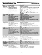
... power or replace batteries. b) Review Exit loop detector settings. c) Check Exit loop wire. Replace defective Exit loop detector. If no AC power, then running on batteries and battery voltage must be 22.0 Vdc or higher. Adjust settings as needed c) Check Interrupt loop wire. TROUBLESHOOTING TROUBLESHOOTING CHART FAULT Gate stops during travel . Charge batteries by AC or solar power or replace batteries a) Use Diagnostic code to -Close. Charge batteries by AC or solar power or replace batteries g) Check Fire Dept input a) Use Diagnostic code to open limit. d) Check if AC power...
... power or replace batteries. b) Review Exit loop detector settings. c) Check Exit loop wire. Replace defective Exit loop detector. If no AC power, then running on batteries and battery voltage must be 22.0 Vdc or higher. Adjust settings as needed c) Check Interrupt loop wire. TROUBLESHOOTING TROUBLESHOOTING CHART FAULT Gate stops during travel . Charge batteries by AC or solar power or replace batteries a) Use Diagnostic code to -Close. Charge batteries by AC or solar power or replace batteries g) Check Fire Dept input a) Use Diagnostic code to open limit. d) Check if AC power...
CSW24V Installation Manual
Page 42
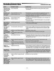
...low power mode. a) Incorrect edge sensor wiring b) Defective edge sensor Alarm sounds for cause of AC/solar power a) Defective or incorrect Operator-to-Operator wiring b) Incorrect Operator-to-Operator wireless learning a) Incorrect Bipart switch setting a) Defective main board to expansion board wiring b) Incorrect input wiring to expansion board c) Defective expansion board or defective main board a) Maglock wired incorrectly Solenoid lock not a) Solenoid wired incorrectly working correctly. Expansion board function not controlling gate. CORRECTIONS a) Adjust force setting...
...low power mode. a) Incorrect edge sensor wiring b) Defective edge sensor Alarm sounds for cause of AC/solar power a) Defective or incorrect Operator-to-Operator wiring b) Incorrect Operator-to-Operator wireless learning a) Incorrect Bipart switch setting a) Defective main board to expansion board wiring b) Incorrect input wiring to expansion board c) Defective expansion board or defective main board a) Maglock wired incorrectly Solenoid lock not a) Solenoid wired incorrectly working correctly. Expansion board function not controlling gate. CORRECTIONS a) Adjust force setting...
CSW24V Installation Manual
Page 45
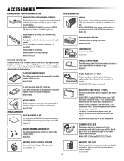
...) WIRELESS ACCESS CONTROL RECEIVER Access control receiver for each gate operator. Model 86LM MISCELLANEOUS HEATER Keeps operator, gearbox and batteries at suitable temperature when outside by Chamberlain after 1993. Model 29-NP712 (standard 7 AMP-Hour Battery or two 7 AMPHour battery service kit K74-30762, 12 Vdc, to satisfy your authorized LiftMaster dealer for optimal heater location) and G6518CSW (Swing replacement heater only) PLUG-IN LOOP DETECTOR Conveniently plugs into existing control board. Not for extended periods of time. Single-button...
...) WIRELESS ACCESS CONTROL RECEIVER Access control receiver for each gate operator. Model 86LM MISCELLANEOUS HEATER Keeps operator, gearbox and batteries at suitable temperature when outside by Chamberlain after 1993. Model 29-NP712 (standard 7 AMP-Hour Battery or two 7 AMPHour battery service kit K74-30762, 12 Vdc, to satisfy your authorized LiftMaster dealer for optimal heater location) and G6518CSW (Swing replacement heater only) PLUG-IN LOOP DETECTOR Conveniently plugs into existing control board. Not for extended periods of time. Single-button...
CSW24V Installation Manual
Page 48
... repaired or replaced with the instructions regarding installation, operation, maintenance and testing. THIS LIMITED WARRANTY DOES NOT COVER NON-DEFECT DAMAGE, DAMAGE CAUSED BY IMPROPER INSTALLATION, OPERATION OR CARE (INCLUDING, BUT NOT LIMITED TO ABUSE, MISUSE, FAILURE TO PROVIDE REASONABLE AND NECESSARY MAINTENANCE, UNAUTHORIZED REPAIRS OR ANY ALTERATIONS TO THIS PRODUCT), LABOR CHARGES FOR REINSTALLING A REPAIRED OR REPLACED UNIT, OR REPLACEMENT OF BATTERIES. ANY SERVICE CALL THAT DETERMINES THE PROBLEM...
... repaired or replaced with the instructions regarding installation, operation, maintenance and testing. THIS LIMITED WARRANTY DOES NOT COVER NON-DEFECT DAMAGE, DAMAGE CAUSED BY IMPROPER INSTALLATION, OPERATION OR CARE (INCLUDING, BUT NOT LIMITED TO ABUSE, MISUSE, FAILURE TO PROVIDE REASONABLE AND NECESSARY MAINTENANCE, UNAUTHORIZED REPAIRS OR ANY ALTERATIONS TO THIS PRODUCT), LABOR CHARGES FOR REINSTALLING A REPAIRED OR REPLACED UNIT, OR REPLACEMENT OF BATTERIES. ANY SERVICE CALL THAT DETERMINES THE PROBLEM...
CSW24V Manual
Page 3
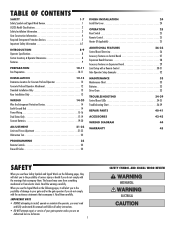
... INSTALLATION 24 Install the Cover 24 OPERATION 25 Reset Switch 25 Remote Control 25 Heater (If Applicable 25 ADDITIONAL FEATURES 26-32 Control Board Overview 26 Accessory Features on Control Board 27 Expansion Board Overview 28 Accessory Features on Expansion Board 29 Limit Setup with a Remote Control 30-31 Gate Operator Setup Examples 32 MAINTENANCE 33 Maintenance Chart 33 Batteries 33 Drive Chain 33 TROUBLESHOOTING 34-39 Control Board LEDs 34-35 Troubleshooting Chart 36-39 REPAIR PARTS 40-41 ACCESSORIES 42-43 WIRING DIAGRAM...
... INSTALLATION 24 Install the Cover 24 OPERATION 25 Reset Switch 25 Remote Control 25 Heater (If Applicable 25 ADDITIONAL FEATURES 26-32 Control Board Overview 26 Accessory Features on Control Board 27 Expansion Board Overview 28 Accessory Features on Expansion Board 29 Limit Setup with a Remote Control 30-31 Gate Operator Setup Examples 32 MAINTENANCE 33 Maintenance Chart 33 Batteries 33 Drive Chain 33 TROUBLESHOOTING 34-39 Control Board LEDs 34-35 Troubleshooting Chart 36-39 REPAIR PARTS 40-41 ACCESSORIES 42-43 WIRING DIAGRAM...

CSW24V Manual
Page 8
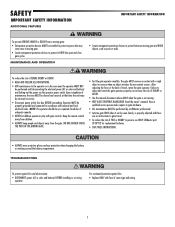
... control (force or travel limits) is adjusted, the other underground utility lines, contact underground utility locating companies BEFORE digging more than 18 inches (46 cm) deep. • ALWAYS wear protective gloves and eye protection when changing the battery or working around the battery compartment. NOTE: The operator should be on a separate fused line of adequate capacity. • ALL electrical connections MUST be located at all times. Gate MUST reverse...
... control (force or travel limits) is adjusted, the other underground utility lines, contact underground utility locating companies BEFORE digging more than 18 inches (46 cm) deep. • ALWAYS wear protective gloves and eye protection when changing the battery or working around the battery compartment. NOTE: The operator should be on a separate fused line of adequate capacity. • ALL electrical connections MUST be located at all times. Gate MUST reverse...
CSW24V Manual
Page 9
... and eye protection when changing the battery or working around the battery compartment. After adjusting the force or the limit of travel . • To reduce the risk of maintenance the area MUST be cleared and secured, at the fuse box BEFORE proceeding. Operator MUST be on contact with fuse of adequate capacity. • NEVER let children operate or play with national and local electrical codes. Keep the remote control away...
... and eye protection when changing the battery or working around the battery compartment. After adjusting the force or the limit of travel . • To reduce the risk of maintenance the area MUST be cleared and secured, at the fuse box BEFORE proceeding. Operator MUST be on contact with fuse of adequate capacity. • NEVER let children operate or play with national and local electrical codes. Keep the remote control away...
CSW24V Manual
Page 11
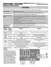
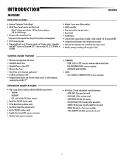
... LOOP: accessory connection • AUX Relays (2) each independently selectable operation: - POWER: ON with up to -Close (TTC) • Maximum Run Timer • Bipart Delay switch (dual gate applications) • Feedback and Diagnostic LEDs • Integrated Radio Receiver and 3-Button Station control, six radio frequencies supporting Security✚ 2.0™ EXPANSION BOARD FEATURES • Plug-in Loop Detector Connectors (Model LOOPDETLM Loop Detector) - Main AC voltage input selection: 120 Vac (factory setting) or 240 Vac (field change) • DC motor...
... LOOP: accessory connection • AUX Relays (2) each independently selectable operation: - POWER: ON with up to -Close (TTC) • Maximum Run Timer • Bipart Delay switch (dual gate applications) • Feedback and Diagnostic LEDs • Integrated Radio Receiver and 3-Button Station control, six radio frequencies supporting Security✚ 2.0™ EXPANSION BOARD FEATURES • Plug-in Loop Detector Connectors (Model LOOPDETLM Loop Detector) - Main AC voltage input selection: 120 Vac (factory setting) or 240 Vac (field change) • DC motor...
CSW24V Manual
Page 28
... for programming remote controls and the network. See Status LED Chart in Limit setting mode. See Adjust Limits section. The LOCK/BIPART DELAY switch is factory set to automatically close the gate. See Bipart Delay section. The TTC is used only for the operator. If the TTC is reset by any signals from the open until the operator receives another command from a control. The TTC is set to OFF. The STATUS LEDs are diagnostic codes...
... for programming remote controls and the network. See Status LED Chart in Limit setting mode. See Adjust Limits section. The LOCK/BIPART DELAY switch is factory set to automatically close the gate. See Bipart Delay section. The TTC is used only for the operator. If the TTC is reset by any signals from the open until the operator receives another command from a control. The TTC is set to OFF. The STATUS LEDs are diagnostic codes...

CSW24V Manual
Page 30
... battery voltage increases. • Option select switch set Aux Relay switches back to open until AC power is faulted and inoperative). After servicing, set to CLOSE forces gate to OPEN, if the EXIT plug-in motion). Com AUX Relay 1 N.O. Use with SAMS (Sequenced Access Management System, jointly with by being pushed off of close limit. Energizes when motor is on a hard command input overrides to their appropriate positions. Not used . 1 Single SBC Com Open Close Stop Button D Control Station A B 3-Button Control...
... battery voltage increases. • Option select switch set Aux Relay switches back to open until AC power is faulted and inoperative). After servicing, set to CLOSE forces gate to OPEN, if the EXIT plug-in motion). Com AUX Relay 1 N.O. Use with SAMS (Sequenced Access Management System, jointly with by being pushed off of close limit. Energizes when motor is on a hard command input overrides to their appropriate positions. Not used . 1 Single SBC Com Open Close Stop Button D Control Station A B 3-Button Control...


