CSW24UL Product Data Sheet
Page 1
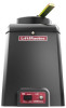
.... CSW24UL SWING GATE OPERATOR SECTION 32 31 00 KEY FEATURES BATTERY BACKUP Up to 24 days of AC power or battery depletion LIMIT SETTING Electronic DUAL GATE CONTROL Bi-part delay or synchronized close capabilities HOMELINK® COMPATIBLE Version 4 and higher SPECIFICATIONS OPERATOR SPEED 90-degree opening in 15 seconds POWER 120V/230VAC single phase ACCESSORY POWER 24VDC, 500mA output; Reference detailed solar chart on product page at LiftMaster.com DIAGNOSTIC DISPLAY LED diagnostic display WIRELESS...
.... CSW24UL SWING GATE OPERATOR SECTION 32 31 00 KEY FEATURES BATTERY BACKUP Up to 24 days of AC power or battery depletion LIMIT SETTING Electronic DUAL GATE CONTROL Bi-part delay or synchronized close capabilities HOMELINK® COMPATIBLE Version 4 and higher SPECIFICATIONS OPERATOR SPEED 90-degree opening in 15 seconds POWER 120V/230VAC single phase ACCESSORY POWER 24VDC, 500mA output; Reference detailed solar chart on product page at LiftMaster.com DIAGNOSTIC DISPLAY LED diagnostic display WIRELESS...

CSW24UL Product Guide - English
Page 2
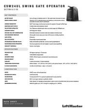
... Technical Support Center: 800.528.2806 To Order: 800.323.2276 *May require an external adapter depending on the model and year of Each Wing to 50 Remote Controls (Unlimited with 1/4 in 13-15 Seconds PRE-MOTION WARNING ALARM - All rights reserved. Operator Duty Rating: High-Cycle, High-Temperature Continuous Duty - CSW24UL 24VDC HIGH-TRAFFIC COMMERCIAL SWING GATE OPERATOR MECHANICS - 24VDC Continuous-Duty Motor - Accessory Power...
... Technical Support Center: 800.528.2806 To Order: 800.323.2276 *May require an external adapter depending on the model and year of Each Wing to 50 Remote Controls (Unlimited with 1/4 in 13-15 Seconds PRE-MOTION WARNING ALARM - All rights reserved. Operator Duty Rating: High-Cycle, High-Temperature Continuous Duty - CSW24UL 24VDC HIGH-TRAFFIC COMMERCIAL SWING GATE OPERATOR MECHANICS - 24VDC Continuous-Duty Motor - Accessory Power...
CSW24UL Wiring Diagram
Page 1
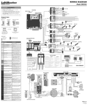
...battery. Make sure connected devices are not accurate, reprogram. Operator may be set limits. Make sure the gate is NOT a 24V battery on expansion board; Review power supply and wiring. Replace APE assembly. 99 Normal Operation No action required WIRING DIAGRAM Model CSW24UL COAXIAL CABLE ANTENNA Control Board DIAGNOSTICS LOOPS CONTROLS Jumper N.C. BRIDGE Orange RECTIFIER Red Black Black Red PRODUCT ID Purple Red Black ALARM White White To Pin 2 To Pin 1 Run Stop/Reset RESET SWITCH Ferrite EMI Filters APS ENCODER Motor LiftMaster.com © 2018, LiftMaster...
...battery. Make sure connected devices are not accurate, reprogram. Operator may be set limits. Make sure the gate is NOT a 24V battery on expansion board; Review power supply and wiring. Replace APE assembly. 99 Normal Operation No action required WIRING DIAGRAM Model CSW24UL COAXIAL CABLE ANTENNA Control Board DIAGNOSTICS LOOPS CONTROLS Jumper N.C. BRIDGE Orange RECTIFIER Red Black Black Red PRODUCT ID Purple Red Black ALARM White White To Pin 2 To Pin 1 Run Stop/Reset RESET SWITCH Ferrite EMI Filters APS ENCODER Motor LiftMaster.com © 2018, LiftMaster...

UL 325-Listed Gate Operators Guide
Page 6
... PRIMARY GATE CLOSES LAST. INHERENT REVERSING SENSOR DETECTS OBSTRUCTIONS AND REVERSES GATE WHEN CLOSING OR STOPS/REVERSES THE GATE WHEN OPENING. SAFE AND SECURE SECURITY+ 2.0® SAFEGUARDS ACCESS WITH AN ENCRYPTED TRI-BAND SIGNAL TO VIRTUALLY ELIMINATE INTERFERENCE AND OFFER EXTENDED RANGE. range: 130 ft.* MONITORED SAFETY ENTRAPMENT EDGES Full line of obstructions. range: 50 ft. BATTERY BACKUP PROVIDES SEAMLESS ACCESS BY PROVIDING STANDBY POWER WHEN THE POWER IS DOWN. SAFETY ADD-ONS: MONITORED THROUGHBEAM PHOTO EYES...
... PRIMARY GATE CLOSES LAST. INHERENT REVERSING SENSOR DETECTS OBSTRUCTIONS AND REVERSES GATE WHEN CLOSING OR STOPS/REVERSES THE GATE WHEN OPENING. SAFE AND SECURE SECURITY+ 2.0® SAFEGUARDS ACCESS WITH AN ENCRYPTED TRI-BAND SIGNAL TO VIRTUALLY ELIMINATE INTERFERENCE AND OFFER EXTENDED RANGE. range: 130 ft.* MONITORED SAFETY ENTRAPMENT EDGES Full line of obstructions. range: 50 ft. BATTERY BACKUP PROVIDES SEAMLESS ACCESS BY PROVIDING STANDBY POWER WHEN THE POWER IS DOWN. SAFETY ADD-ONS: MONITORED THROUGHBEAM PHOTO EYES...

UL 325-Listed Gate Operators Guide
Page 8
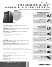
.... PLUG-IN LOOP DETECTOR Prevents the gate from Anywhere with wider polarized beam for maximum cycles on Battery Backup. power efficient for high performance in most popular swing gate operator on a vehicle in the path; range: 90 ft. MONITORED WIRELESS EDGE KIT Low-energy Bluetooth® connection between a LiftMaster Monitored Resistive Edge and the gate operator; GHLIGHTS SOLAR CHARGE Provides up to control gate operator if safety devices fault yet are free...
.... PLUG-IN LOOP DETECTOR Prevents the gate from Anywhere with wider polarized beam for maximum cycles on Battery Backup. power efficient for high performance in most popular swing gate operator on a vehicle in the path; range: 90 ft. MONITORED WIRELESS EDGE KIT Low-energy Bluetooth® connection between a LiftMaster Monitored Resistive Edge and the gate operator; GHLIGHTS SOLAR CHARGE Provides up to control gate operator if safety devices fault yet are free...
UL 325-Listed Gate Operators Guide
Page 12
... UNAUTHORIZED MANUAL OPEN. range: 90 ft. TOTAL SOLUTION ACCESSORIES: RESIDENTIAL TELEPHONE ENTRY SYSTEM Controls access at gated entrances with heater and wider polarized beam, engineered to 114 Cycles or 63 Days of Small, Large and Wraparound Profile Edges that sense obstructions. BACKUP Provides up to 4 transmitters and 2 resistive edges per transmitter. SMOOTH START/STOP OPERATION AND MID-TRAVEL REVERSAL EXTEND OPERATOR HARDWARE LIFE. SAFE AND SECURE SECURITY+ 2.0® SAFEGUARDS ACCESS...
... UNAUTHORIZED MANUAL OPEN. range: 90 ft. TOTAL SOLUTION ACCESSORIES: RESIDENTIAL TELEPHONE ENTRY SYSTEM Controls access at gated entrances with heater and wider polarized beam, engineered to 114 Cycles or 63 Days of Small, Large and Wraparound Profile Edges that sense obstructions. BACKUP Provides up to 4 transmitters and 2 resistive edges per transmitter. SMOOTH START/STOP OPERATION AND MID-TRAVEL REVERSAL EXTEND OPERATOR HARDWARE LIFE. SAFE AND SECURE SECURITY+ 2.0® SAFEGUARDS ACCESS...
UL 325-Listed Gate Operators Guide
Page 18
... to stay aligned; max. HEAVY-DUTY COMMERCIAL GEAR-DRIVEN TRANSMISSION PROVIDES UNS URPA S S ED R E L IA B IL IT Y. SMOOTH START/STOP OPERATION AND MID-TRAVEL REVERSAL EXTEND OPERATOR HARDWARE LIFE. RED/GREEN TRAFFIC LIGHT Assures safe entering and exiting by indicating door status. max. MyQ® TECHNOLOGY ENABLES YOU TO SECURELY CONTROL AND MONITOR YOUR GATE OPERATOR FROM ANYWHERE. PLUG-IN LOOP DETECTOR Identifies vehicles within the gate or door pathway. YELLOW ZINC DICHROMATE RAIL...
... to stay aligned; max. HEAVY-DUTY COMMERCIAL GEAR-DRIVEN TRANSMISSION PROVIDES UNS URPA S S ED R E L IA B IL IT Y. SMOOTH START/STOP OPERATION AND MID-TRAVEL REVERSAL EXTEND OPERATOR HARDWARE LIFE. RED/GREEN TRAFFIC LIGHT Assures safe entering and exiting by indicating door status. max. MyQ® TECHNOLOGY ENABLES YOU TO SECURELY CONTROL AND MONITOR YOUR GATE OPERATOR FROM ANYWHERE. PLUG-IN LOOP DETECTOR Identifies vehicles within the gate or door pathway. YELLOW ZINC DICHROMATE RAIL...
UL 325-Listed Gate Operators Guide
Page 32
... UP TO 130 FT. INTEGRATED DIAGNOSTICS WITH LIFTMASTER® UL® 325 GATE OPERATORS TO SPEED INSTALL AND TROUBLESHOOTING. SAFE AND SECURE PRESSURE-SENSITIVE EDGE SENDS SIGNAL TO STOP AND/OR REVERSE GATE OPERATION WHEN SENSING OBSTRUCTIONS. WIRELESS KEYPAD Provides constant pressure override to Easily Expand Entrapment Zone Protection IGHLIGHT RELIABLE VERSATILE SOLUTION FOR VIRTUALLY ANY ENVIRONMENT. Hold Open/Party Pass enabled with gate operator firmware 4.2 or higher.
... UP TO 130 FT. INTEGRATED DIAGNOSTICS WITH LIFTMASTER® UL® 325 GATE OPERATORS TO SPEED INSTALL AND TROUBLESHOOTING. SAFE AND SECURE PRESSURE-SENSITIVE EDGE SENDS SIGNAL TO STOP AND/OR REVERSE GATE OPERATION WHEN SENSING OBSTRUCTIONS. WIRELESS KEYPAD Provides constant pressure override to Easily Expand Entrapment Zone Protection IGHLIGHT RELIABLE VERSATILE SOLUTION FOR VIRTUALLY ANY ENVIRONMENT. Hold Open/Party Pass enabled with gate operator firmware 4.2 or higher.
Instructions
Page 2
FOR TECHNICAL SUPPORT TO ORDER REPAIR PARTS Call our toll free numbers: Call our toll free numbers: (800) 323-2276 (800) 998-9197 (800) 528-2806 (800) 998-9197 Installation and service information is protected by copyright and contain information proprietary to provide the following information when ordering repair parts: Part Number Part Name Model Number This documentation contains information proprietary to LiftMaster and such information may not be distributed without the prior written...
FOR TECHNICAL SUPPORT TO ORDER REPAIR PARTS Call our toll free numbers: Call our toll free numbers: (800) 323-2276 (800) 998-9197 (800) 528-2806 (800) 998-9197 Installation and service information is protected by copyright and contain information proprietary to provide the following information when ordering repair parts: Part Number Part Name Model Number This documentation contains information proprietary to LiftMaster and such information may not be distributed without the prior written...

Installation Manual
Page 2
... Board 35 MAINTENANCE 36 Important Safety Instructions 36 Maintenance Chart 36 Batteries 37 TROUBLESHOOTING 38 Diagnostic Codes 38 Diagnostic Codes Table 39 Control Board LEDs 41 Troubleshooting Chart 42 APPENDIX 45 Step 8 Solar Panel(s 45 SAMS Wiring with Relays Not Energized 49 Dual Gate Settings 49 Limit Setup with a Remote Control 50 WIRING DIAGRAM 51 REPAIR PARTS 52 ACCESSORIES 53 WARRANTY 55 SAFETY Safety Symbol and Signal Word Review When you see this manual and follow all safety instructions. • DO NOT attempt repair or service...
... Board 35 MAINTENANCE 36 Important Safety Instructions 36 Maintenance Chart 36 Batteries 37 TROUBLESHOOTING 38 Diagnostic Codes 38 Diagnostic Codes Table 39 Control Board LEDs 41 Troubleshooting Chart 42 APPENDIX 45 Step 8 Solar Panel(s 45 SAMS Wiring with Relays Not Energized 49 Dual Gate Settings 49 Limit Setup with a Remote Control 50 WIRING DIAGRAM 51 REPAIR PARTS 52 ACCESSORIES 53 WARRANTY 55 SAFETY Safety Symbol and Signal Word Review When you see this manual and follow all safety instructions. • DO NOT attempt repair or service...

Installation Manual
Page 26
...-Close can radiate radio frequency energy and, if not installed and used in a particular installation. NOTE: The operator will time out of programming mode after 30 seconds. 2. Press and release the LEARN button (operator will beep and green XMITTER LED will need to be set to program. Press the remote control button that may cause undesired operation. NOTE: The operator will time out of 50 Security+ 2.0® remote controls or KPW250 keypads and 2 keyless entries (1 PIN for each remote control button as OPEN, CLOSE, and STOP DESCRIPTION Program a single button...
...-Close can radiate radio frequency energy and, if not installed and used in a particular installation. NOTE: The operator will time out of programming mode after 30 seconds. 2. Press and release the LEARN button (operator will beep and green XMITTER LED will need to be set to program. Press the remote control button that may cause undesired operation. NOTE: The operator will time out of 50 Security+ 2.0® remote controls or KPW250 keypads and 2 keyless entries (1 PIN for each remote control button as OPEN, CLOSE, and STOP DESCRIPTION Program a single button...

Installation Manual
Page 27
... Operator will light). 2. Remove the entrapment protection device wires from the terminal block. 2. Press and release the LEARN button (operator will beep and green XMITTER LED will chirp indicating the timer is canceled. The SET OPEN and SET CLOSE LEDs will turn off the SET OPEN and SET CLOSE LEDs (exiting learn limit mode). 3. Use an internet enabled computer or smartphone to the LiftMaster Internet Gateway and the router. 2. The LiftMaster Internet Gateway will stay in learn button on primary gate) to the LiftMaster...
... Operator will light). 2. Remove the entrapment protection device wires from the terminal block. 2. Press and release the LEARN button (operator will beep and green XMITTER LED will chirp indicating the timer is canceled. The SET OPEN and SET CLOSE LEDs will turn off the SET OPEN and SET CLOSE LEDs (exiting learn limit mode). 3. Use an internet enabled computer or smartphone to the LiftMaster Internet Gateway and the router. 2. The LiftMaster Internet Gateway will stay in learn button on primary gate) to the LiftMaster...

Installation Manual
Page 28
... system). Aux Relay Out - not running on batteries). Use during servicing only to ensure proper gate operation. The thermostat MUST be set to CLOSE. The thermostat MUST be set to OFF. close (timer or control). Run on jurisdiction requirement, set between 45°F and 60°F to determine operator cycles. CLOSE EYES/Interrupt loop reverses a closing gate. Limit Switch Use with SAMS (Sequence Management System). Use with SAMS (Sequence Access 1. Close Typically not required. Connect "Gate Close/Secure" indicator (e.g. PreMotion...
... system). Aux Relay Out - not running on batteries). Use during servicing only to ensure proper gate operation. The thermostat MUST be set to CLOSE. The thermostat MUST be set to OFF. close (timer or control). Run on jurisdiction requirement, set between 45°F and 60°F to determine operator cycles. CLOSE EYES/Interrupt loop reverses a closing gate. Limit Switch Use with SAMS (Sequence Management System). Use with SAMS (Sequence Access 1. Close Typically not required. Connect "Gate Close/Secure" indicator (e.g. PreMotion...

Installation Manual
Page 34
... 1 LED blinks 3 times, 2 LED blinks 6 times, and 3 LED blinks once. Cycle count cannot be reset or changed. Auxiliary relay wiring example RED/GREEN LIGHT FUNCTIONALITY Red light wired to ON 34 GATE STATE AUX RELAY 1 SWITCHES AUX RELAY 2 SWITCHES 1 OFF 2 OFF 3 OFF 1 ON 2 ON 3 ON Closed Red light OFF* Green light OFF Opening Red light ON/Flash Green light OFF Open Red light OFF Green light ON Closing Red light ON/Flash Green light OFF Defined Mid Stop n/a n/a Undefined Mid Stop Red light ON Green light OFF Timer more than 5 seconds Red light OFF Green light...
... 1 LED blinks 3 times, 2 LED blinks 6 times, and 3 LED blinks once. Cycle count cannot be reset or changed. Auxiliary relay wiring example RED/GREEN LIGHT FUNCTIONALITY Red light wired to ON 34 GATE STATE AUX RELAY 1 SWITCHES AUX RELAY 2 SWITCHES 1 OFF 2 OFF 3 OFF 1 ON 2 ON 3 ON Closed Red light OFF* Green light OFF Opening Red light ON/Flash Green light OFF Open Red light OFF Green light ON Closing Red light ON/Flash Green light OFF Defined Mid Stop n/a n/a Undefined Mid Stop Red light ON Green light OFF Timer more than 5 seconds Red light OFF Green light...

Installation Manual
Page 36
... incoming voltage to the operator is within ten percent of travel . The gate MUST reverse on Have a qualified service person make repairs to the operator before servicing. After adjusting the force or the limit of the operator's rating. 36 l Use the manual disconnect release ONLY when the gate is suggested that time the unit may be returned to service the operator. MUST be properly grounded and connected in the area near...
... incoming voltage to the operator is within ten percent of travel . The gate MUST reverse on Have a qualified service person make repairs to the operator before servicing. After adjusting the force or the limit of the operator's rating. 36 l Use the manual disconnect release ONLY when the gate is suggested that time the unit may be returned to service the operator. MUST be properly grounded and connected in the area near...

Installation Manual
Page 39
... Error Minimum number of the battery charge harness. If powered, deactivate the wireless feature and then re-learn the second operator. Make sure you do NOT have a 12V battery on main control board; Replace the APE assembly if necessary. LiftMaster Plug-in wireless edge. If rebooting, ensure enough time for wiring issue or obstruction. Check wired input on a 24V system. Check battery connections and installation. Replace batteries if depleted to run the system. Review...
... Error Minimum number of the battery charge harness. If powered, deactivate the wireless feature and then re-learn the second operator. Make sure you do NOT have a 12V battery on main control board; Replace the APE assembly if necessary. LiftMaster Plug-in wireless edge. If rebooting, ensure enough time for wiring issue or obstruction. Check wired input on a 24V system. Check battery connections and installation. Replace batteries if depleted to run the system. Review...

Installation Manual
Page 40
.... Check inputs and communication method between the main board and the expansion board. Make sure connected devices are not supported. Ensure operator is engaged and free to erase the wireless communication and reprogram the two operators. Check for obstruction. If no obstruction, check that the mechanical assembly is engaged and free to move . See section on Limit and Force Adjustment, and Obstruction Test. Replace APE assembly.
.... Check inputs and communication method between the main board and the expansion board. Make sure connected devices are not supported. Ensure operator is engaged and free to erase the wireless communication and reprogram the two operators. Check for obstruction. If no obstruction, check that the mechanical assembly is engaged and free to move . See section on Limit and Force Adjustment, and Obstruction Test. Replace APE assembly.

Installation Manual
Page 43
...TROUBLESHOOTING SYMPTOM Gate closes, but will not open limit. Photoelectric sensor does not stop or reverse gate. Defective vehicle loop detector c. Review Interrupt loop detector settings. a. Check for an active detector b. Charge batteries by AC or solar power or replace batteries a. If required, replace wire cable. Force adjustment needed . Incorrect edge sensor wiring b. Adjust settings as needed . Replace defective edge sensor. Low battery with LOW BATT option set to N.C. Defective expansion board or defective main board a. Replace defective Shadow loop detector. Exit loop...
...TROUBLESHOOTING SYMPTOM Gate closes, but will not open limit. Photoelectric sensor does not stop or reverse gate. Defective vehicle loop detector c. Review Interrupt loop detector settings. a. Check for an active detector b. Charge batteries by AC or solar power or replace batteries a. If required, replace wire cable. Force adjustment needed . Incorrect edge sensor wiring b. Adjust settings as needed . Replace defective edge sensor. Low battery with LOW BATT option set to N.C. Defective expansion board or defective main board a. Replace defective Shadow loop detector. Exit loop...

Installation Manual
Page 44
... Loop detector c. Check that Solenoid has power (do not power solenoid from obstructions (trees, buildings, etc.) a. Reduce the accessory power draw by using LiftMaster low power accessories c. Relocate the solar panels away from control board accessory power terminals). Add more solar panels b. a. Defective control board a. Quick Close setting incorrect b. Solar operator, insufficient standby time. Excessive accessory power draw c. and COM terminals. a. b. Check AUX Relay switches settings b. and COM. Set AUX Relay to Wiring Diagrams). TROUBLESHOOTING...
... Loop detector c. Check that Solenoid has power (do not power solenoid from obstructions (trees, buildings, etc.) a. Reduce the accessory power draw by using LiftMaster low power accessories c. Relocate the solar panels away from control board accessory power terminals). Add more solar panels b. a. Defective control board a. Quick Close setting incorrect b. Solar operator, insufficient standby time. Excessive accessory power draw c. and COM terminals. a. b. Check AUX Relay switches settings b. and COM. Set AUX Relay to Wiring Diagrams). TROUBLESHOOTING...

Installation Manual
Page 55
... NOT COVER NON-DEFECT DAMAGE, DAMAGE CAUSED BY IMPROPER INSTALLATION, OPERATION OR CARE (INCLUDING, BUT NOT LIMITED TO ABUSE, MISUSE, FAILURE TO PROVIDE REASONABLE AND NECESSARY MAINTENANCE, UNAUTHORIZED REPAIRS OR ANY ALTERATIONS TO THIS PRODUCT), LABOR CHARGES FOR REINSTALLING A REPAIRED OR REPLACED UNIT, OR REPLACEMENT OF BATTERIES. Some states do not allow the exclusion or limitation of -purchase receipt with new or factoryrebuilt parts...
... NOT COVER NON-DEFECT DAMAGE, DAMAGE CAUSED BY IMPROPER INSTALLATION, OPERATION OR CARE (INCLUDING, BUT NOT LIMITED TO ABUSE, MISUSE, FAILURE TO PROVIDE REASONABLE AND NECESSARY MAINTENANCE, UNAUTHORIZED REPAIRS OR ANY ALTERATIONS TO THIS PRODUCT), LABOR CHARGES FOR REINSTALLING A REPAIRED OR REPLACED UNIT, OR REPLACEMENT OF BATTERIES. Some states do not allow the exclusion or limitation of -purchase receipt with new or factoryrebuilt parts...


