
"Manufacturer's Certification for Credit" Manual
Page 1
... Model Number(s) of Property Qualifying for Credit LiftMaster LA412 Solar Gate Operator System (Single Gate Model LA4121PKG) LiftMaster LA412 Solar Gate Operator System (Dual Gate Model LA412-2PKG) LiftMaster LA412 Solar Residential DC Linear Actuator (Single Gate Model LA4121PKGDC) LiftMaster LA412 Solar Residential DC Linear Actuator (Dual Gate Model LA412-2PKGDC) LiftMaster LA400 Residential DC Linear Actuator (Single Gate...
... Model Number(s) of Property Qualifying for Credit LiftMaster LA412 Solar Gate Operator System (Single Gate Model LA4121PKG) LiftMaster LA412 Solar Gate Operator System (Dual Gate Model LA412-2PKG) LiftMaster LA412 Solar Residential DC Linear Actuator (Single Gate Model LA4121PKGDC) LiftMaster LA412 Solar Residential DC Linear Actuator (Dual Gate Model LA412-2PKGDC) LiftMaster LA400 Residential DC Linear Actuator (Single Gate...
CSL24U Sell Sheet Manual
Page 1
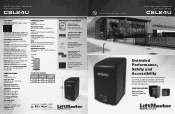
...20" 14.6" 21.1" It's Time to Make Gate Safety a Priority 24VDC High-Traffic Commercial Slide Gate Operator CSL24U Unrivaled Performance, Safety and Accessibility Built to deliver unsurpassed safety and performance, our 2016 UL Listed Gate Operators ...Solar option available. SOLAR-READY ULTRA-RELIABLE SYSTEM Simple solar conversion delivers power when you need it most and is pushed off the interrupt loop. SECURITY+ 2.0® ON-BOARD RADIO RECEIVER Up to 140°F (60°C). UL USAGE CLASSIFICATION I, II, III, and IV. All Rights Reserved. 845 Larch Ave., Elmhurst, IL 60126 LiftMaster...
...20" 14.6" 21.1" It's Time to Make Gate Safety a Priority 24VDC High-Traffic Commercial Slide Gate Operator CSL24U Unrivaled Performance, Safety and Accessibility Built to deliver unsurpassed safety and performance, our 2016 UL Listed Gate Operators ...Solar option available. SOLAR-READY ULTRA-RELIABLE SYSTEM Simple solar conversion delivers power when you need it most and is pushed off the interrupt loop. SECURITY+ 2.0® ON-BOARD RADIO RECEIVER Up to 140°F (60°C). UL USAGE CLASSIFICATION I, II, III, and IV. All Rights Reserved. 845 Larch Ave., Elmhurst, IL 60126 LiftMaster...
LiftMaster Gate Operator Feature Chart Manual
Page 1
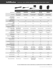
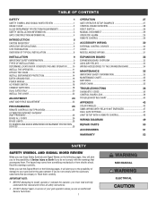
...Gate Operation PosiLock® Feature Fire Department Compliant Electronic Limits Expansion Board Included (2) Aux Relays, Quick Close/ Anti-Tailgate Plug-in -class features, see solar chart for Zone 1 (6 hours sunlight per day Yes Yes Yes Yes - Yes Yes Optional With Optional Expansion Board With Optional Expansion Board - 3 ... Cycles 300 cycles per day 850 lbs. 100 cycles per day 850 lbs. 100 cycles per day (see specific product sell sheets at LiftMaster.com *Cycles noted are for specific details) 800 lbs. 120 cycles per day 1000 lbs. 250 cycles per day For more information about...
...Gate Operation PosiLock® Feature Fire Department Compliant Electronic Limits Expansion Board Included (2) Aux Relays, Quick Close/ Anti-Tailgate Plug-in -class features, see solar chart for Zone 1 (6 hours sunlight per day Yes Yes Yes Yes - Yes Yes Optional With Optional Expansion Board With Optional Expansion Board - 3 ... Cycles 300 cycles per day 850 lbs. 100 cycles per day 850 lbs. 100 cycles per day (see specific product sell sheets at LiftMaster.com *Cycles noted are for specific details) 800 lbs. 120 cycles per day 1000 lbs. 250 cycles per day For more information about...
LiftMaster Gate Operator Feature Chart Manual
Page 2
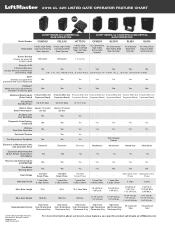
...information about our best-in -Class Approx. 16 cycles Approx. 22 cycles Solar Performance* per day per day - - - - - Best-in -class features, see specific product sell sheets at LiftMaster.com Electronic or Mechanical Limits with your smartphone Yes Yes Yes Yes Yes Yes...HP 2000 lbs. - 2016 UL 325 LISTED GATE OPERATOR FEATURE CHART Model Number ELITE® SERIES DC COMMERCIAL GATE OPERATORS CSW24U CSL24U HCTDCU ELITE® SERIES AC COMMERCIAL/INDUSTRIAL GATE OPERATORS CSW200 SL3000 SL585 SL595 24VDC High-Traffic Description Commercial Swing Gate Operator 24VDC...
...information about our best-in -Class Approx. 16 cycles Approx. 22 cycles Solar Performance* per day per day - - - - - Best-in -class features, see specific product sell sheets at LiftMaster.com Electronic or Mechanical Limits with your smartphone Yes Yes Yes Yes Yes Yes...HP 2000 lbs. - 2016 UL 325 LISTED GATE OPERATOR FEATURE CHART Model Number ELITE® SERIES DC COMMERCIAL GATE OPERATORS CSW24U CSL24U HCTDCU ELITE® SERIES AC COMMERCIAL/INDUSTRIAL GATE OPERATORS CSW200 SL3000 SL585 SL595 24VDC High-Traffic Description Commercial Swing Gate Operator 24VDC...

CSL24U Wiring Diagram Manual
Page 1
... second number shown after the code sequence number is NOT a 24V battery on a 12V system. CODE COLOR KEY: LiftMaster System Installed System Informational External Entrapment Protection Inherent Entrapment Protection CODE MEANING SOLUTION Main control board has experienced an internal Disconnect ...action required. See section on 33AH Battery Harness (K94-37236) Diode Solar Panels (Optional) 20W minimum - 60W maximum, wired in . Control Station Fire Department WIRING DIAGRAM Model CSL24U Exit Loop Shadow Loop LOOPS DIAGNOSTICS Interrupt Loop Photoelectric Sensors for close cycle...
... second number shown after the code sequence number is NOT a 24V battery on a 12V system. CODE COLOR KEY: LiftMaster System Installed System Informational External Entrapment Protection Inherent Entrapment Protection CODE MEANING SOLUTION Main control board has experienced an internal Disconnect ...action required. See section on 33AH Battery Harness (K94-37236) Diode Solar Panels (Optional) 20W minimum - 60W maximum, wired in . Control Station Fire Department WIRING DIAGRAM Model CSL24U Exit Loop Shadow Loop LOOPS DIAGNOSTICS Interrupt Loop Photoelectric Sensors for close cycle...
CSL24U Installation Manual
Page 3
...DUAL GATES ONLY 20 INSTALL THE COVER 22 ADJUSTMENT 23 LIMIT AND FORCE ADJUSTMENT 23 PROGRAMMING 25 REMOTE CONTROLS (NOT PROVIDED 25 LIFTMASTER INTERNET GATEWAY (NOT PROVIDED 26 ERASE ALL CODES 26 ERASE LIMITS 26 TO REMOVE AND ERASE MONITORED ENTRAPMENT PROTECTION DEVICES 26 ... MAINTENANCE CHART 35 BATTERIES 35 DRIVE CHAIN 35 TROUBLESHOOTING 36 DIAGNOSTIC CODES 36 CONTROL BOARD LEDS 39 TROUBLESHOOTING CHART 40 APPENDIX 43 SOLAR PANEL(S 43 SAMS WIRING WITH RELAYS NOT ENERGIZED 47 DUAL GATE SETTINGS 47 LIMIT SETUP WITH A REMOTE CONTROL 48 WIRING DIAGRAM...
...DUAL GATES ONLY 20 INSTALL THE COVER 22 ADJUSTMENT 23 LIMIT AND FORCE ADJUSTMENT 23 PROGRAMMING 25 REMOTE CONTROLS (NOT PROVIDED 25 LIFTMASTER INTERNET GATEWAY (NOT PROVIDED 26 ERASE ALL CODES 26 ERASE LIMITS 26 TO REMOVE AND ERASE MONITORED ENTRAPMENT PROTECTION DEVICES 26 ... MAINTENANCE CHART 35 BATTERIES 35 DRIVE CHAIN 35 TROUBLESHOOTING 36 DIAGNOSTIC CODES 36 CONTROL BOARD LEDS 39 TROUBLESHOOTING CHART 40 APPENDIX 43 SOLAR PANEL(S 43 SAMS WIRING WITH RELAYS NOT ENERGIZED 47 DUAL GATE SETTINGS 47 LIMIT SETUP WITH A REMOTE CONTROL 48 WIRING DIAGRAM...

CSL24U Installation Manual
Page 8
RPM and Current Sense 3 inputs per board - for use in vehicular slide gate applications: Usage Classification Main AC Supply System Operating Voltage Accessory Power Solar Power Max Maximum Gate Weight Minimum Gate Travel Distance Maximum Gate Travel Distance Maximum Gate Travel Speed Maximum Daily Cycle Rate Maximum Duty Cycle Operating ...
RPM and Current Sense 3 inputs per board - for use in vehicular slide gate applications: Usage Classification Main AC Supply System Operating Voltage Accessory Power Solar Power Max Maximum Gate Weight Minimum Gate Travel Distance Maximum Gate Travel Distance Maximum Gate Travel Speed Maximum Daily Cycle Rate Maximum Duty Cycle Operating ...

CSL24U Installation Manual
Page 18
... wiring MUST be connected to your local area. Install the earth ground rod within 3 feet of maintenance the area MUST be returned to Solar Panels section in separate conduits. This operator can be a single, whole piece of the remote controls will be reduced and the operator will...be run in the Appendix. NOTE: If the operator is not grounded properly the range of wire. Upon completion of the operator. 2. SOLAR APPLICATIONS: For solar applications refer to service. • Disconnect power at that time the unit may be cleared and secured, at the fuse box BEFORE proceeding....
... wiring MUST be connected to your local area. Install the earth ground rod within 3 feet of maintenance the area MUST be returned to Solar Panels section in separate conduits. This operator can be a single, whole piece of the remote controls will be reduced and the operator will...be run in the Appendix. NOTE: If the operator is not grounded properly the range of wire. Upon completion of the operator. 2. SOLAR APPLICATIONS: For solar applications refer to service. • Disconnect power at that time the unit may be cleared and secured, at the fuse box BEFORE proceeding....

CSL24U Installation Manual
Page 21
... the red (+) wire from the 33AH wire harness kit to the positive (+) terminal on the battery as shown. 4. The batteries are for battery backup or solar installation. Turn ON the AC power switch on the control board and disconnect it. 2. J15 Plug Red (+) Black (-) Red (+) wire from new wire harness kit...
... the red (+) wire from the 33AH wire harness kit to the positive (+) terminal on the battery as shown. 4. The batteries are for battery backup or solar installation. Turn ON the AC power switch on the control board and disconnect it. 2. J15 Plug Red (+) Black (-) Red (+) wire from new wire harness kit...

CSL24U Installation Manual
Page 33
...-of -sight) • STOP and COM: Stops a moving gate. Relay is off when motor is off . (control board) SOLENOID (2 Terminals, N.O. NOTE: To conserve power for solar applications, the lock relay will only activate for maglocks. Hard close limit. (control board) Maglock _ + (not provided) Solenoid Lock _ + (not provided) MISCELLANEOUS WIRING THREE BUTTON...
...-of -sight) • STOP and COM: Stops a moving gate. Relay is off when motor is off . (control board) SOLENOID (2 Terminals, N.O. NOTE: To conserve power for solar applications, the lock relay will only activate for maglocks. Hard close limit. (control board) Maglock _ + (not provided) Solenoid Lock _ + (not provided) MISCELLANEOUS WIRING THREE BUTTON...
CSL24U Installation Manual
Page 35
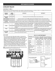
... ON ON Energizes when motor is stored on (gate in thousands), set all the LEDs will sound. ON ON OFF Energizes when AC power or solar power is between 1,000 and 9,999,000 cycles. See below. Cycle count is closed, set Aux Relay switches back to the ON setting for connection...
... ON ON Energizes when motor is stored on (gate in thousands), set all the LEDs will sound. ON ON OFF Energizes when AC power or solar power is between 1,000 and 9,999,000 cycles. See below. Cycle count is closed, set Aux Relay switches back to the ON setting for connection...
CSL24U Installation Manual
Page 37
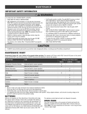
... Signs Make sure they are no more frequent maintenance checks. • Limits may be performed until disconnecting the electrical power (AC or solar and battery) and locking-out the power via the operator power switch. NOTE: The chain should be on the operator will degrade over...unit may have no obstructions to gate travel , retest the gate operator. Batteries do not perform well in extremely cold temperatures. Use only LiftMaster part 29-NP712 for every 10 feet of chain length. NOTE: The operator should have to be tightened. MAINTENANCE CHART Disconnect all wire...
... Signs Make sure they are no more frequent maintenance checks. • Limits may be performed until disconnecting the electrical power (AC or solar and battery) and locking-out the power via the operator power switch. NOTE: The chain should be on the operator will degrade over...unit may have no obstructions to gate travel , retest the gate operator. Batteries do not perform well in extremely cold temperatures. Use only LiftMaster part 29-NP712 for every 10 feet of chain length. NOTE: The operator should have to be tightened. MAINTENANCE CHART Disconnect all wire...

CSL24U Installation Manual
Page 38
... the display will start saving over the oldest codes as new codes occur. For continued protection against fire and electrocution: • DISCONNECT power (AC or solar and battery) BEFORE installing or servicing operator. TO SCROLL THROUGH THE SAVED CODES TO EXIT Press and release the STOP button to the most recent...
... the display will start saving over the oldest codes as new codes occur. For continued protection against fire and electrocution: • DISCONNECT power (AC or solar and battery) BEFORE installing or servicing operator. TO SCROLL THROUGH THE SAVED CODES TO EXIT Press and release the STOP button to the most recent...

CSL24U Installation Manual
Page 41
TROUBLESHOOTING CONTROL BOARD LEDS STATUS LEDS INPUT OFF POWER ON OFF state AC charger or Solar power available BATT OFF CHARGING ON Not charging Three stage battery charging TIMER OFF The timer is disabled ON The timer is enabled MEDIUM BLINK (1 ...
TROUBLESHOOTING CONTROL BOARD LEDS STATUS LEDS INPUT OFF POWER ON OFF state AC charger or Solar power available BATT OFF CHARGING ON Not charging Three stage battery charging TIMER OFF The timer is disabled ON The timer is enabled MEDIUM BLINK (1 ...
CSL24U Installation Manual
Page 42
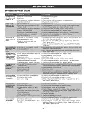
... " detector g) Defective control board g) Replace defective control board Gate moves, but cannot set correct limits. c) Charges batteries by AC or solar power or replace batteries d) Open or Close input active d) Check all Open and Close inputs for a "stuck on" input e) Entrapment Protection... a) Use manual disconnect, manually move easily and freely through its entire range, limit to limit. Charge batteries by AC or solar power or replace batteries. 40 TROUBLESHOOTING TROUBLESHOOTING CHART SYMPTOM POSSIBLE CAUSES SOLUTIONS Operator does not a) No power to control board a)...
... " detector g) Defective control board g) Replace defective control board Gate moves, but cannot set correct limits. c) Charges batteries by AC or solar power or replace batteries d) Open or Close input active d) Check all Open and Close inputs for a "stuck on" input e) Entrapment Protection... a) Use manual disconnect, manually move easily and freely through its entire range, limit to limit. Charge batteries by AC or solar power or replace batteries. 40 TROUBLESHOOTING TROUBLESHOOTING CHART SYMPTOM POSSIBLE CAUSES SOLUTIONS Operator does not a) No power to control board a)...

CSL24U Installation Manual
Page 43
...correct. If no AC power, then running on batteries and battery voltage must be 23.0 Vdc or higher. Charge batteries by AC or solar power or replace batteries On dual-gate system, incorrect gate opens first or closes first. a) Review Interrupt loop detector settings. Adjust settings ...Expansion board function not controlling gate. Press the reset button to OFF. If no AC power, then running . Charge batteries by AC or solar power or replace batteries. Alarm beeps when running on expansion board. a) Incorrect Bipart switch setting a) Expansion board setting b) Constant pressure to...
...correct. If no AC power, then running on batteries and battery voltage must be 23.0 Vdc or higher. Charge batteries by AC or solar power or replace batteries On dual-gate system, incorrect gate opens first or closes first. a) Review Interrupt loop detector settings. Adjust settings ...Expansion board function not controlling gate. Press the reset button to OFF. If no AC power, then running . Charge batteries by AC or solar power or replace batteries. Alarm beeps when running on expansion board. a) Incorrect Bipart switch setting a) Expansion board setting b) Constant pressure to...

CSL24U Installation Manual
Page 44
...Check that Solenoid has power (do not power solenoid from obstructions (trees, buildings, etc.) a) Add more solar panels b) Reduce the accessory power draw by using LiftMaster low power accessories c) Use batteries with higher amp hour (AH) rating 42 c) Set AUX Relay to...voltage is connected to Accessory power not working correctly. and COM. a) Add more solar panels b) Reduce the accessory power draw by using LiftMaster low power accessories c) Replace batteries d) Relocate the solar panels away from control board accessory power terminals). a) Anti-Tail setting incorrect b) ...
...Check that Solenoid has power (do not power solenoid from obstructions (trees, buildings, etc.) a) Add more solar panels b) Reduce the accessory power draw by using LiftMaster low power accessories c) Use batteries with higher amp hour (AH) rating 42 c) Set AUX Relay to...voltage is connected to Accessory power not working correctly. and COM. a) Add more solar panels b) Reduce the accessory power draw by using LiftMaster low power accessories c) Replace batteries d) Relocate the solar panels away from control board accessory power terminals). a) Anti-Tail setting incorrect b) ...

CSL24U Installation Manual
Page 45
.... Solar panels should be used with a solar application. We recommend LiftMaster low power draw accessories to minimize power draw, refer to improve performance. NOTE: Input solar power is not supported in series (Model SOLPNL10W12V). • A maximum of six 10W solar panels (Model SOLPNL10W12V). • Solar Battery... weather and a reduced number of hours of the solar panel NOT AVAILABLE NOT AVAILABLE 3 2 1 1 43 APPENDIX STEP 6 SOLAR PANEL(S) NOT PROVIDED. This is not in an open area clear of two 10W solar panels in northern climates where temperatures reach below 32˚...
.... Solar panels should be used with a solar application. We recommend LiftMaster low power draw accessories to minimize power draw, refer to improve performance. NOTE: Input solar power is not supported in series (Model SOLPNL10W12V). • A maximum of six 10W solar panels (Model SOLPNL10W12V). • Solar Battery... weather and a reduced number of hours of the solar panel NOT AVAILABLE NOT AVAILABLE 3 2 1 1 43 APPENDIX STEP 6 SOLAR PANEL(S) NOT PROVIDED. This is not in an open area clear of two 10W solar panels in northern climates where temperatures reach below 32˚...

CSL24U Installation Manual
Page 46
SOLAR PANEL(S) SOLAR USAGE GUIDE APPENDIX Typical System Standby Battery Current Consumption (mA) System voltage Main board with no radios programmed One or more LiftMaster® remote controls programmed MyQ® device or wireless dual gate programmed Expansion board Per loop detector LOOPDETLM (up to 3 loop .... 24V 2.7 mA +1 mA +2.4 mA +11.1 mA +3.8 mA BATTERY CURRENT DRAW (mA) 10W SOLAR PANEL 5 (Must use 24V solar 15 panel) 20 40 60 20W SOLAR PANEL 5 (Two 10W 12V panels in 15 series) 20 50 100 40W SOLAR PANEL 5 (Two 20W 12V panels in 15 series) 20 100 200 60W...
SOLAR PANEL(S) SOLAR USAGE GUIDE APPENDIX Typical System Standby Battery Current Consumption (mA) System voltage Main board with no radios programmed One or more LiftMaster® remote controls programmed MyQ® device or wireless dual gate programmed Expansion board Per loop detector LOOPDETLM (up to 3 loop .... 24V 2.7 mA +1 mA +2.4 mA +11.1 mA +3.8 mA BATTERY CURRENT DRAW (mA) 10W SOLAR PANEL 5 (Must use 24V solar 15 panel) 20 40 60 20W SOLAR PANEL 5 (Two 10W 12V panels in 15 series) 20 50 100 40W SOLAR PANEL 5 (Two 20W 12V panels in 15 series) 20 100 200 60W...

CSL24U Installation Manual
Page 47
...m) from buildings and trees. In general, the panel(s) should be located up to west. • Wire runs should be clear of the installation. Solar Panel (Facing South) South 180° Sun's Position Operator South 45 APPENDIX STEP 6 continued... If the panel(s) is not casting a shadow, the... battery is critical to determine direction. The solar panel(s) can be kept as short as possible. TIPS: • Tall trees or buildings that will block the panel during the winter months...
...m) from buildings and trees. In general, the panel(s) should be located up to west. • Wire runs should be clear of the installation. Solar Panel (Facing South) South 180° Sun's Position Operator South 45 APPENDIX STEP 6 continued... If the panel(s) is not casting a shadow, the... battery is critical to determine direction. The solar panel(s) can be kept as short as possible. TIPS: • Tall trees or buildings that will block the panel during the winter months...


