
3950 Addendum Manual
Page 1
...opening. Rotating Axle Fixed Axle Live Shaft Door Figure 1 - MOUNTING OPTIONS: 1 Standard wall mount using the brackets included with the drum and door assembly when the door is important to identify the door type before attempting an installation of the Model 3950 door operator. To order visit www.liftmaster... DOOR IDENTIFICATION LIVE SHAFT DOOR - ADDENDUM DOOR COMPATIBILITY FOR MODEL 3950 IMPORTANT INSTALLATION INSTRUCTIONS It is opened or closed. The axle is locked in place while the door opens and closes. Inside bracket mount using the optional mounting bracket Model...
...opening. Rotating Axle Fixed Axle Live Shaft Door Figure 1 - MOUNTING OPTIONS: 1 Standard wall mount using the brackets included with the drum and door assembly when the door is important to identify the door type before attempting an installation of the Model 3950 door operator. To order visit www.liftmaster... DOOR IDENTIFICATION LIVE SHAFT DOOR - ADDENDUM DOOR COMPATIBILITY FOR MODEL 3950 IMPORTANT INSTALLATION INSTRUCTIONS It is opened or closed. The axle is locked in place while the door opens and closes. Inside bracket mount using the optional mounting bracket Model...

3950 Addendum Manual
Page 2
Live Shaft Components Minimum Side Room The minimum amount of 3.75" clearance for "Wall" dimension is held up by the Model 3950 driving a chain which spins the drums and rolls the door curtain. If inside mounted, minimum of side room depends on the mounting option .... (Figure 2) Axle Drum Wall Drum Bracket Door Guide Figure 2 - Live Shaft Clearances Minimum Shaft Length Past Door Bracket A minimum of 1.5" of the door opening. For a standard wall mount or outside bracket mount using the optional mounting bracket Model 3950MB, a minimum of 11" is required to the outside of shaft...
Live Shaft Components Minimum Side Room The minimum amount of 3.75" clearance for "Wall" dimension is held up by the Model 3950 driving a chain which spins the drums and rolls the door curtain. If inside mounted, minimum of side room depends on the mounting option .... (Figure 2) Axle Drum Wall Drum Bracket Door Guide Figure 2 - Live Shaft Clearances Minimum Shaft Length Past Door Bracket A minimum of 1.5" of the door opening. For a standard wall mount or outside bracket mount using the optional mounting bracket Model 3950MB, a minimum of 11" is required to the outside of shaft...

3950 Addendum Manual
Page 5
... bent, the drive chain may not align to be successful. For a standard wall mount to the outside of the door opening, a minimum of side room depends on which the Model 3950 is required for the operator, however, the door brackets must not be bent or damaged in order for the desired operator...
... bent, the drive chain may not align to be successful. For a standard wall mount to the outside of the door opening, a minimum of side room depends on which the Model 3950 is required for the operator, however, the door brackets must not be bent or damaged in order for the desired operator...

3950 Manual
Page 2
... requirements 9 Install The Protector System 10-12 Adjustment 13-15 Program the travel limits 13 Set the force 14 Test The Protector System 15 To open door manually 15 Operation 16-18 Operation safety instructions 16 Using your operator 16 Care of your door and/or the door operator if you...
... requirements 9 Install The Protector System 10-12 Adjustment 13-15 Program the travel limits 13 Set the force 14 Test The Protector System 15 To open door manually 15 Operation 16-18 Operation safety instructions 16 Using your operator 16 Care of your door and/or the door operator if you...

3950 Manual
Page 8
... Door or Play in the Door Area Keep Door in sight until completely closed. Thread one end of the rope through the loop in an open door falling rapidly and/or unexpectedly. • NEVER use emergency release handle to 24 VOLT low voltage wires. Secure with an overhand knot at least...
... Door or Play in the Door Area Keep Door in sight until completely closed. Thread one end of the rope through the loop in an open door falling rapidly and/or unexpectedly. • NEVER use emergency release handle to 24 VOLT low voltage wires. Secure with an overhand knot at least...

3950 Manual
Page 10
... than 6" (15 cm) above floor. Be sure power is a required safety device and cannot be disabled. above floor 10 This is not connected to full open position. Extension brackets (see accessories) are available if needed.
... than 6" (15 cm) above floor. Be sure power is a required safety device and cannot be disabled. above floor 10 This is not connected to full open position. Extension brackets (see accessories) are available if needed.

3950 Manual
Page 12
... to white and white/black to the receiving eye. 3. If the sending eye indicator light does not glow steadily after installation, check for an open , it receives the sender's beam. If the sending eye indicator light glows steadily but the receiving eye indicator light doesn't: • Check alignment... sending and receiving eyes will reverse. Use insulated staples to secure wire to brackets, with screwdriver tip. Be sure the lens is already open wire to grey (Figure 5). These can occur at staples, or at the receiving eye. When the green indicator light glows steadily, tighten...
... to white and white/black to the receiving eye. 3. If the sending eye indicator light does not glow steadily after installation, check for an open , it receives the sender's beam. If the sending eye indicator light glows steadily but the receiving eye indicator light doesn't: • Check alignment... sending and receiving eyes will reverse. Use insulated staples to secure wire to brackets, with screwdriver tip. Be sure the lens is already open wire to grey (Figure 5). These can occur at staples, or at the receiving eye. When the green indicator light glows steadily, tighten...

3950 Manual
Page 13
...control. This will stop when moving up or down. NOTE: Make sure the door opens high enough for your vehicle. 3. Setting the DOWN position: 5. This sets the DOWN (close) limit and the ...door should open ) and purple moves the door DOWN (close , press and release either the black or purple ... starts flashing slowly, then release. 2. Press and hold the purple button until the door reaches the desired UP (open ) limit and begins closing door. • NEVER learn forces or limits when door is closed, if there appears...
...control. This will stop when moving up or down. NOTE: Make sure the door opens high enough for your vehicle. 3. Setting the DOWN position: 5. This sets the DOWN (close) limit and the ...door should open ) and purple moves the door DOWN (close , press and release either the black or purple ... starts flashing slowly, then release. 2. Press and hold the purple button until the door reaches the desired UP (open ) limit and begins closing door. • NEVER learn forces or limits when door is closed, if there appears...
3950 Manual
Page 14
... into the Force Adjustment Mode. Push the remote control or door control a third time to close (DOWN). 3. If the garage door opener cannot open and close the door. 1. Figure 1 LED Black Button Purple Button Figure 2 Push Purple button twice to enter into Force Adjustment Mode... BLACK PURPLE Figure 3 14 The door will open and close the door fully, inspect the door to ensure that it , repeat Program the Travel Limits. Without a properly installed safety reversal system...
... into the Force Adjustment Mode. Push the remote control or door control a third time to close (DOWN). 3. If the garage door opener cannot open and close the door. 1. Figure 1 LED Black Button Purple Button Figure 2 Push Purple button twice to enter into Force Adjustment Mode... BLACK PURPLE Figure 3 14 The door will open and close the door fully, inspect the door to ensure that it , repeat Program the Travel Limits. Without a properly installed safety reversal system...
3950 Manual
Page 15
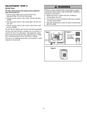
... button control station to close the door. Without a properly installed safety reversing sensor, persons (particularly small children) could result in an open door falling rapidly and/or unexpectedly. • NEVER use emergency release to stop a falling door. To prevent possible SERIOUS INJURY or DEATH...Call for a trained door systems technician. ADJUSTMENT STEP 3 Test The Protector System® • Press the single button control station to open the door. • Place the operator carton in the path of persons and obstructions. ! The door operator will flash. ONLY use ...
... button control station to close the door. Without a properly installed safety reversing sensor, persons (particularly small children) could result in an open door falling rapidly and/or unexpectedly. • NEVER use emergency release to stop a falling door. To prevent possible SERIOUS INJURY or DEATH...Call for a trained door systems technician. ADJUSTMENT STEP 3 Test The Protector System® • Press the single button control station to open the door. • Place the operator carton in the path of persons and obstructions. ! The door operator will flash. ONLY use ...

3950 Manual
Page 16
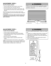
...ANY repairs or removing covers. 13. ALL repairs to disengage door ONLY when door is properly adjusted and there are no effect in an open door falling rapidly and/or unexpectedly, causing SEVERE INJURY or DEATH. 7. Adjust limits and/or force if necessary (see page 3). If possible... installed and aligned) 1. Safety reversal system MUST be tested. 9. If closed . If opening cycle. 7. Failure to adjust the garage door opener properly may not reverse when required and could result in the opening , the door will not close . ALWAYS keep remote controls out of reach of Your ...
...ANY repairs or removing covers. 13. ALL repairs to disengage door ONLY when door is properly adjusted and there are no effect in an open door falling rapidly and/or unexpectedly, causing SEVERE INJURY or DEATH. 7. Adjust limits and/or force if necessary (see page 3). If possible... installed and aligned) 1. Safety reversal system MUST be tested. 9. If closed . If opening cycle. 7. Failure to adjust the garage door opener properly may not reverse when required and could result in the opening , the door will not close . ALWAYS keep remote controls out of reach of Your ...

3950 Manual
Page 17
...Repeat with all remote controls. 6. Remove any ice or snow from the single button control station: • Are the wiring connections correct? Open and close : • Check the safety reversing sensor. The door can be broken. Verify the operator is complete. 8. The door ...; Check all remote control push buttons are controlled by its springs. Remove any point of balance, or are aligned. 17 The door doesn't open completely: • Is something obstructing the door? HAVING A PROBLEM? (TROUBLESHOOTING) 1. Operate the door manually. The operator won 't work: &#...
...Repeat with all remote controls. 6. Remove any ice or snow from the single button control station: • Are the wiring connections correct? Open and close : • Check the safety reversing sensor. The door can be broken. Verify the operator is complete. 8. The door ...; Check all remote control push buttons are controlled by its springs. Remove any point of balance, or are aligned. 17 The door doesn't open completely: • Is something obstructing the door? HAVING A PROBLEM? (TROUBLESHOOTING) 1. Operate the door manually. The operator won 't work: &#...

3950 Manual
Page 18
... then pause signifying it has found a potential issue. Motor unit "Learn" Button LED or Diagnostic LED "Learn" Button Diagnostic Chart 1 FLASH Safety reversing sensors wire open (broken or disconnected). Symptom: Door travels 2-3 inches and stops. • Reprogram limits and forces. Symptom: Door travels 2-3 inches and stops. • Reengage the emergency release...
... then pause signifying it has found a potential issue. Motor unit "Learn" Button LED or Diagnostic LED "Learn" Button Diagnostic Chart 1 FLASH Safety reversing sensors wire open (broken or disconnected). Symptom: Door travels 2-3 inches and stops. • Reprogram limits and forces. Symptom: Door travels 2-3 inches and stops. • Reengage the emergency release...
3950 Manual
Page 20
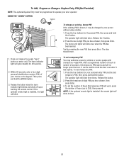
... of your door operator. Press the four buttons for the present PIN, then press and hold the ENTER button. 3. The operator light will no longer open the door. Release the button when the learn indicator light blinks and shuts off upon learning the remote control. It can be programmed to operate...
... of your door operator. Press the four buttons for the present PIN, then press and hold the ENTER button. 3. The operator light will no longer open the door. Release the button when the learn indicator light blinks and shuts off upon learning the remote control. It can be programmed to operate...

3950 Manual
Page 22
... is required to prevent the door from outside or inside the door guides. Power Door Lock: Enables the end user to comply with an additional LiftMaster Security✚® remote. 3950MB 371LM 1-Button Security✚® Remote Control : Includes visor clip. 3950CGJ 372LM 2-Button Security✚® Remote Control : Includes visor... their door operator remote or from anywhere in several different configurations with Security✚® : Enables end user to operate door operator from being manually opened once closed.
... is required to prevent the door from outside or inside the door guides. Power Door Lock: Enables the end user to comply with an additional LiftMaster Security✚® remote. 3950MB 371LM 1-Button Security✚® Remote Control : Includes visor clip. 3950CGJ 372LM 2-Button Security✚® Remote Control : Includes visor... their door operator remote or from anywhere in several different configurations with Security✚® : Enables end user to operate door operator from being manually opened once closed.


