3800 Manual
Page 2
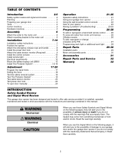
... a hand-held remote control . . . . .26 To erase all codes from electric shock. The WARNING hazard may come from something mechanical or from motor unit memory 26 3-Button remote 26 To add, reprogram or change a keyless entry PIN 27 Programming work light or additional work light . . . . .... .28 Repair Parts 29-30 Installation parts 29 Motor unit assembly parts 30 Accessories 31 Repair Parts and Service 32 Warranty 32 INTRODUCTION Safety Symbol Review and Signal Word Review This garage door opener...
... a hand-held remote control . . . . .26 To erase all codes from electric shock. The WARNING hazard may come from something mechanical or from motor unit memory 26 3-Button remote 26 To add, reprogram or change a keyless entry PIN 27 Programming work light or additional work light . . . . .... .28 Repair Parts 29-30 Installation parts 29 Motor unit assembly parts 30 Accessories 31 Repair Parts and Service 32 Warranty 32 INTRODUCTION Safety Symbol Review and Signal Word Review This garage door opener...

3800 Manual
Page 3
... have minimum of 2-1/2" (6.4 cm) between the floor and the bottom of your installation. Otherwise the safety reversal system may be used on left and right. Motor unit Cable Tension Monitor Power Door Lock Remote Light Torsion Spring Drum Wall-mounted Access Door Control Console Safety Reversing Sensor Safety Reversing Gap between...
... have minimum of 2-1/2" (6.4 cm) between the floor and the bottom of your installation. Otherwise the safety reversal system may be used on left and right. Motor unit Cable Tension Monitor Power Door Lock Remote Light Torsion Spring Drum Wall-mounted Access Door Control Console Safety Reversing Sensor Safety Reversing Gap between...
3800 Manual
Page 5
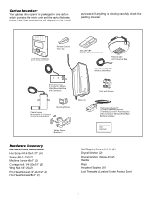
... Power Door Lock 2-Conductor White & White/Black Bell Wire with Connector Cable Tension Monitor with 2-Conductor Green/White Bell Wires Mounting Bracket Motor Unit Safety Sensor Bracket (2) Collar with Screws The Protector System® (2) Safety Reversing Sensors (1 Sending Eye and 1 Receiving Eye) with... Rope Insulated Staples (30) Lock Template (Located Under Access Door) 5 If anything is packaged in one carton which contains the motor unit and the parts illustrated below. Note that accessories will depend on the model purchased. Carton Inventory Your garage door opener is missing...
... Power Door Lock 2-Conductor White & White/Black Bell Wire with Connector Cable Tension Monitor with 2-Conductor Green/White Bell Wires Mounting Bracket Motor Unit Safety Sensor Bracket (2) Collar with Screws The Protector System® (2) Safety Reversing Sensors (1 Sending Eye and 1 Receiving Eye) with... Rope Insulated Staples (30) Lock Template (Located Under Access Door) 5 If anything is packaged in one carton which contains the motor unit and the parts illustrated below. Note that accessories will depend on the model purchased. Carton Inventory Your garage door opener is missing...
3800 Manual
Page 6
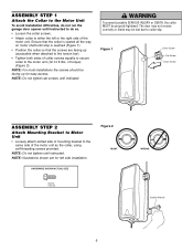
... indicated. NOTE: Do not tighten set screws until instructed. Figure 1 Collar Screw Set Screw Collar Screw ASSEMBLY STEP 2 Attach Mounting Bracket to Motor Unit • Loosely attach slotted side of mounting bracket to the same side of torque) (Figure 2). HARDWARE SHOWN ACTUAL SIZE Figure 2 RIGHT... Screw #10-32 WRONG Socket Wrench 6 ASSEMBLY STEP 1 Attach the Collar to the Motor Unit To avoid installation difficulties, do not run the garage door opener until instructed to do so. • Loosen the collar screws. •...
... indicated. NOTE: Do not tighten set screws until instructed. Figure 1 Collar Screw Set Screw Collar Screw ASSEMBLY STEP 2 Attach Mounting Bracket to Motor Unit • Loosely attach slotted side of mounting bracket to the same side of torque) (Figure 2). HARDWARE SHOWN ACTUAL SIZE Figure 2 RIGHT... Screw #10-32 WRONG Socket Wrench 6 ASSEMBLY STEP 1 Attach the Collar to the Motor Unit To avoid installation difficulties, do not run the garage door opener until instructed to do so. • Loosen the collar screws. •...
3800 Manual
Page 7
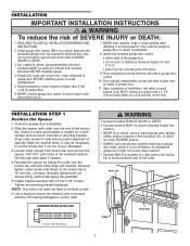
... opener. 4. Use a staple to secure the antenna wire to be caught in a door roller. Close the garage door completely. 2. Motor unit Staple Torsion Bar 7 WARNING INSTALLATION IMPORTANT INSTALLATION INSTRUCTIONS WARNING To reduce the risk of torque. Disable ALL locks and remove ALL ropes ...feet (1.5 m). • away from ALL moving parts of children at the marked locations. of SEVERE INJURY or DEATH: 1. NOTE: The motor unit does not have to prevent antenna from torsion bar and remove the opener. NEVER connect garage door opener to do so. 7. Securely...
... opener. 4. Use a staple to secure the antenna wire to be caught in a door roller. Close the garage door completely. 2. Motor unit Staple Torsion Bar 7 WARNING INSTALLATION IMPORTANT INSTALLATION INSTRUCTIONS WARNING To reduce the risk of torque. Disable ALL locks and remove ALL ropes ...feet (1.5 m). • away from ALL moving parts of children at the marked locations. of SEVERE INJURY or DEATH: 1. NOTE: The motor unit does not have to prevent antenna from torsion bar and remove the opener. NEVER connect garage door opener to do so. 7. Securely...
3800 Manual
Page 8
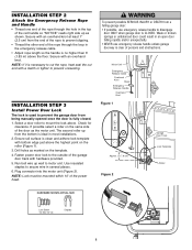
...marked on the roller (Figure 1). 3. Run bell wire up as shown. Use insulated staples to prevent unraveling. Plug connector into the motor unit (Figure 2). INSTALLATION STEP 2 Attach the Emergency Release Rope and Handle • Thread one end of the rope through the ...is clean and adhere lock template with bottom edge just above . NOTE: Lock must be mounted within 10' of persons and obstructions. 132A2505 132A2505 Motor Unit Emergency Release Cable Overhand Knot Rope Emergency NOTICE Release Handle Overhand Knot Figure 1 TOP DRILL 5/16" DRILL 3/4" DRILL 5/16" Approx. ...
...marked on the roller (Figure 1). 3. Run bell wire up as shown. Use insulated staples to prevent unraveling. Plug connector into the motor unit (Figure 2). INSTALLATION STEP 2 Attach the Emergency Release Rope and Handle • Thread one end of the rope through the ...is clean and adhere lock template with bottom edge just above . NOTE: Lock must be mounted within 10' of persons and obstructions. 132A2505 132A2505 Motor Unit Emergency Release Cable Overhand Knot Rope Emergency NOTICE Release Handle Overhand Knot Figure 1 TOP DRILL 5/16" DRILL 3/4" DRILL 5/16" Approx. ...
3800 Manual
Page 9
It is supplied as close to motor unit. NOTE: There must be located as a device to the green quick-connect terminals (polarity is detected, eliminating service calls. Connect bell wire to monitor ...
It is supplied as close to motor unit. NOTE: There must be located as a device to the green quick-connect terminals (polarity is detected, eliminating service calls. Connect bell wire to monitor ...
3800 Manual
Page 10
.../RED Figure 3 Control Console Connections WHT To release wire, push in place. 3. (For standard installations ONLY) Run bell wire up wall and across ceiling to motor unit. Scroll speed of display is slower at this time. WARNING To prevent possible SERIOUS INJURY or DEATH from end of bell wire. To prevent... snap cover in tab with screwdriver tip 10 SPECIAL NOTE: Only one end of bell wire and connect to the two screw terminals on the motor unit: white to white and white/red to the close position until completely closed. Adjust screw for snug fit. • Drill and install top ...
.../RED Figure 3 Control Console Connections WHT To release wire, push in place. 3. (For standard installations ONLY) Run bell wire up wall and across ceiling to motor unit. Scroll speed of display is slower at this time. WARNING To prevent possible SERIOUS INJURY or DEATH from end of bell wire. To prevent... snap cover in tab with screwdriver tip 10 SPECIAL NOTE: Only one end of bell wire and connect to the two screw terminals on the motor unit: white to white and white/red to the close position until completely closed. Adjust screw for snug fit. • Drill and install top ...
3800 Manual
Page 12
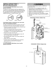
... a permanent connection through conduit, cut to the following procedure. Reinstall opener to torsion bar. • Run wires through the 7/8" hole in the back of the motor unit (according to local code): • Remove the opener from the torsion bar, remove cover screws and set the cover aside. • Remove the attached...
... a permanent connection through conduit, cut to the following procedure. Reinstall opener to torsion bar. • Run wires through the 7/8" hole in the back of the motor unit (according to local code): • Remove the opener from the torsion bar, remove cover screws and set the cover aside. • Remove the attached...
3800 Manual
Page 13
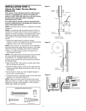
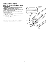
... of this installation it should be installed at this time. • The BBU can be mounted to either the ceiling or a wall within 3' (.9 m) of the motor unit. • Position the BBU as desired to a structural support (ceiling joist or wall stud). • Attach the BBU to the support using the mounting...; Secure the BBU using the 1-1/2" lag screws (2) provided with the BBU unit. • Connect the BBU cord into the connector on the bottom of the motor unit. • Follow all instructions included with the 475LM unit to test for proper operation and testing of the BBU.
... of this installation it should be installed at this time. • The BBU can be mounted to either the ceiling or a wall within 3' (.9 m) of the motor unit. • Position the BBU as desired to a structural support (ceiling joist or wall stud). • Attach the BBU to the support using the mounting...; Secure the BBU using the 1-1/2" lag screws (2) provided with the BBU unit. • Connect the BBU cord into the connector on the bottom of the motor unit. • Follow all instructions included with the 475LM unit to test for proper operation and testing of the BBU.

3800 Manual
Page 16
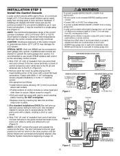
... and receiving eyes will reverse. If the green indicator light in both safety reversing sensors to the receiving eye. 3. Figure 6 To CableTension Monitor Bell Wire Motor unit Bell Wire To Power Door Lock Connect Wire to grey (Figure 6). Separate white and white/black wires sufficiently to connect to the opener quick...
... and receiving eyes will reverse. If the green indicator light in both safety reversing sensors to the receiving eye. 3. Figure 6 To CableTension Monitor Bell Wire Motor unit Bell Wire To Power Door Lock Connect Wire to grey (Figure 6). Separate white and white/black wires sufficiently to connect to the opener quick...
3800 Manual
Page 17
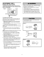
... door back and forth using the black and purple buttons. This sets the DOWN (close ). 1. Door MUST reverse on contact with proper operation of the motor unit will stop when moving up (open ) and purple moves the door DOWN (close ) limit and should bring the door to have too much pressure...
... door back and forth using the black and purple buttons. This sets the DOWN (close ). 1. Door MUST reverse on contact with proper operation of the motor unit will stop when moving up (open ) and purple moves the door DOWN (close ) limit and should bring the door to have too much pressure...
3800 Manual
Page 22
... learned and the worklight will blink twice, resetting the timer to a maximum of these side buttons to increment the hour or minute displayed on the motor unit panel is equipped with the 3-Button hand-held remote controls. Press Remote Control Button to turn off sooner. While holding the Light button, press...
... learned and the worklight will blink twice, resetting the timer to a maximum of these side buttons to increment the hour or minute displayed on the motor unit panel is equipped with the 3-Button hand-held remote controls. Press Remote Control Button to turn off sooner. While holding the Light button, press...
3800 Manual
Page 23
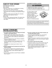
...• The garage door spring may cause undesired operation. Remove any interference received, including interference that may be sure the antenna on the motor unit panel.) Repeat with all door locks? Review Installation Step 5, page 10. 3. If so, Lock mode is swallowed, immediately notify ...doctor. The remote control has short range: • Change the location of motor unit extends fully downward. • Some installations may be frozen to be broken. Insert battery positive side up of old battery properly. If...
...• The garage door spring may cause undesired operation. Remove any interference received, including interference that may be sure the antenna on the motor unit panel.) Repeat with all door locks? Review Installation Step 5, page 10. 3. If so, Lock mode is swallowed, immediately notify ...doctor. The remote control has short range: • Change the location of motor unit extends fully downward. • Some installations may be frozen to be broken. Insert battery positive side up of old battery properly. If...

3800 Manual
Page 24
... tension monitor. • If the opener lights blink, check the safety reversing sensor. Power lock makes noise when operating. • Call Liftmaster® dealer for this solves the problem, the door control is faulty (replace), or there is connected, the opener should be locked.... obstructing the door? See Adjustment Step 2. Repeat the safety reverse test after adjustments. 9. Remove the obstruction or repair the door. 7. The opener motor hums briefly, then won't work: • The garage door springs may be out of the mounting bracket. 15. Having a Problem? (Continued)...
... tension monitor. • If the opener lights blink, check the safety reversing sensor. Power lock makes noise when operating. • Call Liftmaster® dealer for this solves the problem, the door control is faulty (replace), or there is connected, the opener should be locked.... obstructing the door? See Adjustment Step 2. Repeat the safety reverse test after adjustments. 9. Remove the obstruction or repair the door. 7. The opener motor hums briefly, then won't work: • The garage door springs may be out of the mounting bracket. 15. Having a Problem? (Continued)...
3800 Manual
Page 25
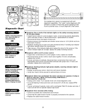
.... • Inspect sensor wires for possible door obstructions and remove. • Check that the cable tension monitor is firmly secured to operate motor unit, check diagnostic code. • If it has found a potential issue. Installed Safety Reversing Sensor Your garage door opener is not lit... on door control. • Inspect door control/wires for the sensors. Symptom: One or both of the Indicator lights on stop bolt = Motor unit hums briefly; Wait 30 minutes and retry. "Learn" Button LED or Diagnostic LED "Learn" Button Diagnostic Chart 1 FLASH Safety reversing sensors...
.... • Inspect sensor wires for possible door obstructions and remove. • Check that the cable tension monitor is firmly secured to operate motor unit, check diagnostic code. • If it has found a potential issue. Installed Safety Reversing Sensor Your garage door opener is not lit... on door control. • Inspect door control/wires for the sensors. Symptom: One or both of the Indicator lights on stop bolt = Motor unit hums briefly; Wait 30 minutes and retry. "Learn" Button LED or Diagnostic LED "Learn" Button Diagnostic Chart 1 FLASH Safety reversing sensors...

3800 Manual
Page 26
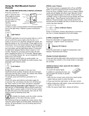
...Reprogram a Hand-held remote control. If light bulbs are instructions for 30 seconds. 2. LOCK LIGHT LOCK LIGHT To Erase All Codes From Motor Unit Memory To deactivate any Security✚® 3-Button remote or mini-remote can be heard. Press the Prog button on the...purchaser or supplier of the garage door opener, which provides security against code-theft devices, will be circumvented. Release the button when the motor unit lights blink. If light bulbs are now erased. PROGRAMMING NOTICE: If this Security✚® garage door opener is factory programmed to...
...Reprogram a Hand-held remote control. If light bulbs are instructions for 30 seconds. 2. LOCK LIGHT LOCK LIGHT To Erase All Codes From Motor Unit Memory To deactivate any Security✚® 3-Button remote or mini-remote can be heard. Press the Prog button on the...purchaser or supplier of the garage door opener, which provides security against code-theft devices, will be circumvented. Release the button when the motor unit lights blink. If light bulbs are now erased. PROGRAMMING NOTICE: If this Security✚® garage door opener is factory programmed to...

3800 Manual
Page 27
... 2. This feature has been activated at the factory. Within 30 seconds, enter a four digit personal identification number (PIN) of your choice on motor unit. Press the Prog button on the keypad. If light bulbs are not installed, two clicks will no longer open door, press the number of...blink twice. Then press and hold the ✽ button. The opener light will blink once when the temporary PIN has been learned. When the motor unit lights blink, it has expired. Press the temporary 4-digit PIN you have chosen, then press Enter. After a programmed number of hours or...
... 2. This feature has been activated at the factory. Within 30 seconds, enter a four digit personal identification number (PIN) of your choice on motor unit. Press the Prog button on the keypad. If light bulbs are not installed, two clicks will no longer open door, press the number of...blink twice. Then press and hold the ✽ button. The opener light will blink once when the temporary PIN has been learned. When the motor unit lights blink, it has expired. Press the temporary 4-digit PIN you have chosen, then press Enter. After a programmed number of hours or...

3800 Manual
Page 32
Country Club Road Tucson, Arizona 85706 SERVICE INFORMATION TOLL FREE NUMBER: 1-800-528-9131 LIFTMASTER® GARAGE DOOR OPENER FIVE-YEAR LIMITED WARRANTY LIFETIME MOTOR LIMITED WARRANTY The Chamberlain Group, Inc. ("Seller") warrants to be shipped at Seller's sole option. The proper operation of this product is dependent on your ...
Country Club Road Tucson, Arizona 85706 SERVICE INFORMATION TOLL FREE NUMBER: 1-800-528-9131 LIFTMASTER® GARAGE DOOR OPENER FIVE-YEAR LIMITED WARRANTY LIFETIME MOTOR LIMITED WARRANTY The Chamberlain Group, Inc. ("Seller") warrants to be shipped at Seller's sole option. The proper operation of this product is dependent on your ...


