
3280 Manual
Page 2
... and signal word review 2 Preparing your garage door 3 Tools needed 3 Planning 4 Carton inventory 5 Hardware inventory 5 Assembly 6-7 Attach the rail to the motor unit 6 Set the belt tension 6 Attach the belt cap retainer 7 Installation 7-22 Installation safety instructions 7 Determine the header... bracket location 8 Install the header bracket 9 Attach the rail to the header bracket 10 Position the opener 11 Hang the opener 12 Install the door control 13 Install the light...
... and signal word review 2 Preparing your garage door 3 Tools needed 3 Planning 4 Carton inventory 5 Hardware inventory 5 Assembly 6-7 Attach the rail to the motor unit 6 Set the belt tension 6 Attach the belt cap retainer 7 Installation 7-22 Installation safety instructions 7 Determine the header... bracket location 8 Install the header bracket 9 Attach the rail to the header bracket 10 Position the opener 11 Hang the opener 12 Install the door control 13 Install the light...
3280 Manual
Page 5
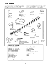
...is packaged in the foam. LOCK LIGHT Multi-Function Door Control Panel SECURITY✚® 3-Button Remote Control Models 3280 (1) 3280-267 (2) Remote Control Transmitter Visor Clip Styrofoam Belt Cap Retainer Belt Motor Unit with 2 Light Lenses SECURITY✚® Keyless Entry ...Model 3280-267 ONLY One-Piece Rail CEILING MOUNT ONLY UP Door Bracket Belt Pulley Bracket Trolley 2-Conductor Bell Wire White & White/Red Header Bracket Curved ...
...is packaged in the foam. LOCK LIGHT Multi-Function Door Control Panel SECURITY✚® 3-Button Remote Control Models 3280 (1) 3280-267 (2) Remote Control Transmitter Visor Clip Styrofoam Belt Cap Retainer Belt Motor Unit with 2 Light Lenses SECURITY✚® Keyless Entry ...Model 3280-267 ONLY One-Piece Rail CEILING MOUNT ONLY UP Door Bracket Belt Pulley Bracket Trolley 2-Conductor Bell Wire White & White/Red Header Bracket Curved ...

3280 Manual
Page 6
...Place a 7/16" open end wrench on the threaded shaft until it is finger tight against the trolley (Figure 3). ASSEMBLY STEP 1 Attach the Rail to the Motor Unit To avoid installation difficulties, do not run the garage door opener until instructed to do so. • Remove the two ...BEFORE 1" (2.5 cm) Figure 3 AFTER RELEASE 1-1/4" (3.18 cm) Figure 2 6 USE ONLY THIS TYPE AND SIZE BOLT Washered Bolt 5/16"-18x1/2" Rail Hole Sprocket Rail Hole ASSEMBLY STEP 2 Set the Belt Tension • By hand, thread the spring trolley nut on the square end. Rotate about 1/4 turn until ...
...Place a 7/16" open end wrench on the threaded shaft until it is finger tight against the trolley (Figure 3). ASSEMBLY STEP 1 Attach the Rail to the Motor Unit To avoid installation difficulties, do not run the garage door opener until instructed to do so. • Remove the two ...BEFORE 1" (2.5 cm) Figure 3 AFTER RELEASE 1-1/4" (3.18 cm) Figure 2 6 USE ONLY THIS TYPE AND SIZE BOLT Washered Bolt 5/16"-18x1/2" Rail Hole Sprocket Rail Hole ASSEMBLY STEP 2 Set the Belt Tension • By hand, thread the spring trolley nut on the square end. Rotate about 1/4 turn until ...
3280 Manual
Page 10
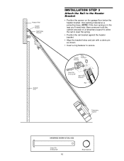
Header Bracket Ring Fastener Clevis Pin 5/16"x2-3/4" Belt Pulley Bracket Rail Temporary Support HARDWARE SHOWN ACTUAL SIZE Clevis Pin 5/16"x2-3/4" 10 Ring Fastener Use packing material as shown. • Insert a ring fastener to the Header ... the opener on the garage floor below the header bracket. Have someone hold the opener securely on a temporary support to allow the rail to clear the spring. • Position the rail bracket against the header bracket. • Align the bracket holes and join with a clevis pin as a protective base. Header Wall Header...
Header Bracket Ring Fastener Clevis Pin 5/16"x2-3/4" Belt Pulley Bracket Rail Temporary Support HARDWARE SHOWN ACTUAL SIZE Clevis Pin 5/16"x2-3/4" 10 Ring Fastener Use packing material as shown. • Insert a ring fastener to the Header ... the opener on the garage floor below the header bracket. Have someone hold the opener securely on a temporary support to allow the rail to clear the spring. • Position the rail bracket against the header bracket. • Align the bracket holes and join with a clevis pin as a protective base. Header Wall Header...
3280 Manual
Page 11
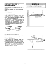
... remain disconnected until Installation Step 12 is used to disconnect inner and outer sections. INSTALLATION STEP 4 Position the Opener Follow instructions which apply to -rail distance. • Remove foam packaging. • Raise the opener onto a stepladder. You will need help at this point. To prevent damage... • Open the door all the way and place a 2x4 on its side is used to garage door, rest garage door opener rail on 2x4 placed on the trolley release arm to determine the correct mounting height from ceiling. SECTIONAL DOOR OR ONE-PIECE DOOR WITH TRACK ...
... remain disconnected until Installation Step 12 is used to disconnect inner and outer sections. INSTALLATION STEP 4 Position the Opener Follow instructions which apply to -rail distance. • Remove foam packaging. • Raise the opener onto a stepladder. You will need help at this point. To prevent damage... • Open the door all the way and place a 2x4 on its side is used to garage door, rest garage door opener rail on 2x4 placed on the trolley release arm to determine the correct mounting height from ceiling. SECTIONAL DOOR OR ONE-PIECE DOOR WITH TRACK ...
3280 Manual
Page 12
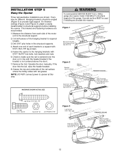
...the opener. Check to structural supports of the hanging bracket to provide rigid support. If the door hits the rail, raise the header bracket. 8. FINISHED CEILING - Measure the distance from a falling garage door opener, fasten it SECURELY to make sure the...the door). 7. Fasten the opener to the structural support. 2. HARDWARE SHOWN ACTUAL SIZE To avoid possible SERIOUS INJURY from each bracket to a support with rail grease. Figure 1 Structural Supports Measure Distance Bolt 5/16"-18x7/8" Lock Washer 5/16" Nut 5/16"-18 Lag Screws 5/16"-18x1-7/8" Figure 2 Bracket ...
...the opener. Check to structural supports of the hanging bracket to provide rigid support. If the door hits the rail, raise the header bracket. 8. FINISHED CEILING - Measure the distance from a falling garage door opener, fasten it SECURELY to make sure the...the door). 7. Fasten the opener to the structural support. 2. HARDWARE SHOWN ACTUAL SIZE To avoid possible SERIOUS INJURY from each bracket to a support with rail grease. Figure 1 Structural Supports Measure Distance Bolt 5/16"-18x7/8" Lock Washer 5/16" Nut 5/16"-18 Lag Screws 5/16"-18x1-7/8" Figure 2 Bracket ...
3280 Manual
Page 33
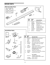
...red Curved door arm section NOT SHOWN 41A2770-6 Installation hardware bag (includes hardware listed on page 5). 114A3083 Owner's manual 114A3083SP Spanish manual 33 REPAIR PARTS Rail Assembly Parts 1 2 4 8 Installation Parts LOCK LIGHT 13 2 4 5 6 NOTICE 8 CEILING MOUNT ONLY UP 7 9 10 11 12 6...Master link kit 2 41B5424 Belt pulley bracket 3 41B3869-1 Complete trolley assembly 4 109B33 Trolley clip 5 2777BD One-piece T-rail 2778BD Complete rail 8' (2.4m) 2770BD Complete rail 10' (3m) 6 41A5434-11 Full belt assembly 7 41B4103 Tensioner assembly 8 83A11...
...red Curved door arm section NOT SHOWN 41A2770-6 Installation hardware bag (includes hardware listed on page 5). 114A3083 Owner's manual 114A3083SP Spanish manual 33 REPAIR PARTS Rail Assembly Parts 1 2 4 8 Installation Parts LOCK LIGHT 13 2 4 5 6 NOTICE 8 CEILING MOUNT ONLY UP 7 9 10 11 12 6...Master link kit 2 41B5424 Belt pulley bracket 3 41B3869-1 Complete trolley assembly 4 109B33 Trolley clip 5 2777BD One-piece T-rail 2778BD Complete rail 8' (2.4m) 2770BD Complete rail 10' (3m) 6 41A5434-11 Full belt assembly 7 41B4103 Tensioner assembly 8 83A11...


