3255 Manual
Page 19
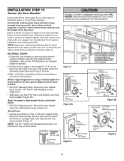
..."-18x2" UP Door Bracket Lock Washer 5/16" Nut 5/16"-18 Figure 2B Figure 2A (Not Provided) Bolt 5/16"x2" Inside Edge of Door or Reinforcement Board Vertical Centerline of Garage Door UP Figure 3 Self-Threading Screw 1/4"-14x5/8" Vertical Centerline of door bracket. A vertical reinforcement brace should be long enough to be...
..."-18x2" UP Door Bracket Lock Washer 5/16" Nut 5/16"-18 Figure 2B Figure 2A (Not Provided) Bolt 5/16"x2" Inside Edge of Door or Reinforcement Board Vertical Centerline of Garage Door UP Figure 3 Self-Threading Screw 1/4"-14x5/8" Vertical Centerline of door bracket. A vertical reinforcement brace should be long enough to be...
3255 Manual
Page 25
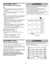
... a 2x4 laid flat) ADJUSTMENT STEP 4 Test The Protector System® • Press the remote control push button to open , place a 1-1/2" (3.8 cm) board (or a 2x4 laid flat) on the 1-1/2" (3.8 cm) board, remove the obstruction and run the opener through 3 or 4 complete travel limits) is misaligned or obstructed). The garage door opener will not...
... a 2x4 laid flat) ADJUSTMENT STEP 4 Test The Protector System® • Press the remote control push button to open , place a 1-1/2" (3.8 cm) board (or a 2x4 laid flat) on the 1-1/2" (3.8 cm) board, remove the obstruction and run the opener through 3 or 4 complete travel limits) is misaligned or obstructed). The garage door opener will not...
3255 Manual
Page 30
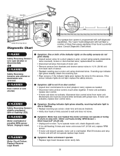
...number of sensor. • Reattach sending eye to wall and does not move. Symptom: Motor unit doesn't operate. • Replace logic board because motor rarely fails. 30 OR 2 FLASHES Safety Reversing Sensors wire shorted or black/white wire reversed. 3 FLASHES Door control or wire... trolley is firmly secured to motor unit using shortened wires. The "Learn" button/diagnostic LED will not operate replace logic board. Replace Receiver Logic Board. Consult Diagnostic Chart below. 1 FLASH Safety Reversing Sensors wire open (broken or disconnected). If motor unit activates, replace ...
...number of sensor. • Reattach sending eye to wall and does not move. Symptom: Motor unit doesn't operate. • Replace logic board because motor rarely fails. 30 OR 2 FLASHES Safety Reversing Sensors wire shorted or black/white wire reversed. 3 FLASHES Door control or wire... trolley is firmly secured to motor unit using shortened wires. The "Learn" button/diagnostic LED will not operate replace logic board. Replace Receiver Logic Board. Consult Diagnostic Chart below. 1 FLASH Safety Reversing Sensors wire open (broken or disconnected). If motor unit activates, replace ...
3255 Manual
Page 34
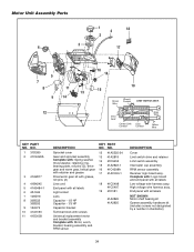
UP DN Drive Gear Center Limit Contact (Up) Contact Grey Wire Yellow Wire KEY PART NO. Complete with: Logic board and end panel with : Motor, worm, bracket, bearing assembly and RPM sensor KEY PART NO. NO. 1 31D380 2 41C4220A 3 41A2817 4 41B4245 5 41A5484-1 6 4A1344 7 108D79 8 30B532 30B533 9 ...-1 18 41C5498 41C5497 19 41D181 41A2826 41A2825 DESCRIPTION Cover Limit switch drive and retainer Limit switch assembly Interrupter cup assembly RPM sensor assembly Receiver logic board assy. High voltage wire harness assy.
UP DN Drive Gear Center Limit Contact (Up) Contact Grey Wire Yellow Wire KEY PART NO. Complete with: Logic board and end panel with : Motor, worm, bracket, bearing assembly and RPM sensor KEY PART NO. NO. 1 31D380 2 41C4220A 3 41A2817 4 41B4245 5 41A5484-1 6 4A1344 7 108D79 8 30B532 30B533 9 ...-1 18 41C5498 41C5497 19 41D181 41A2826 41A2825 DESCRIPTION Cover Limit switch drive and retainer Limit switch assembly Interrupter cup assembly RPM sensor assembly Receiver logic board assy. High voltage wire harness assy.


