1355 Manual
Page 6
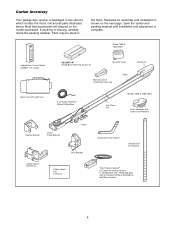
... and installation is missing, carefully check the packing material. If anything is shown on the model purchased. Model 1355 & 1345 ONLY Lighted Door Control Button w/6ABx1-1/2" screws SECURITY✚® Single-Button Remote Control (1) Sprocket Cover Remote Control Transmitter Visor...and Washers Curved Door Arm Section Straight Door Arm Section The Protector System® (2) Safety Reversing Sensors (1 Sending Eye and 1 Receiving Eye) with 2-Conductor White & White/Black Bell Wire attached 6 Parts may be stuck in two cartons which contain the motor unit and all parts...
... and installation is missing, carefully check the packing material. If anything is shown on the model purchased. Model 1355 & 1345 ONLY Lighted Door Control Button w/6ABx1-1/2" screws SECURITY✚® Single-Button Remote Control (1) Sprocket Cover Remote Control Transmitter Visor...and Washers Curved Door Arm Section Straight Door Arm Section The Protector System® (2) Safety Reversing Sensors (1 Sending Eye and 1 Receiving Eye) with 2-Conductor White & White/Black Bell Wire attached 6 Parts may be stuck in two cartons which contain the motor unit and all parts...
1355 Manual
Page 18
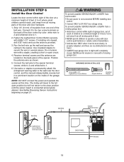
...of 5 feet (1.5 m) where small children cannot reach, and away from one end of the bell wire. NEVER permit anyone to 1. 6. See Safety Reversing Sensor instructions beginning on the back panel of the garage door. If installing into drywall, drill 5/32" ...properly adjusted, and there are located on page 21. HARDWARE SHOWN ACTUAL SIZE Screw 6ABx1-1/2" Lighted Door Control Button Drywall Anchors Insulated Staples Bell Wire Bell Wire W-H2T R-E1D Lighted Door Control Button Terminal Screws Lighted Door Control Button Opener Terminal Screws BACK PANEL 1 2 3 9 1 7 3 5...
...of 5 feet (1.5 m) where small children cannot reach, and away from one end of the bell wire. NEVER permit anyone to 1. 6. See Safety Reversing Sensor instructions beginning on the back panel of the garage door. If installing into drywall, drill 5/32" ...properly adjusted, and there are located on page 21. HARDWARE SHOWN ACTUAL SIZE Screw 6ABx1-1/2" Lighted Door Control Button Drywall Anchors Insulated Staples Bell Wire Bell Wire W-H2T R-E1D Lighted Door Control Button Terminal Screws Lighted Door Control Button Opener Terminal Screws BACK PANEL 1 2 3 9 1 7 3 5...

1355 Manual
Page 23
...eye. Figure 5 Wing Nut 1/4"-20 Carriage Bolt 1/4"-20x1/2" Lens TROUBLESHOOTING THE SAFETY REVERSING SENSORS 1. Figure 6 Bell Wire Finished Ceiling Connect Wire to 3 (Figure 6). Use wing nuts to fasten sensors to wall and ceiling. • Strip 1/4" (6 mm) of insulation from both the... aiming directly at terminal connections. • Incorrect wiring between sensors and opener. • A broken wire. 2. Use insulated staples to secure wire to brackets, with lenses pointing toward each sensor. Separate white and white/black wires sufficiently to connect to the opener terminal screws: ...
...eye. Figure 5 Wing Nut 1/4"-20 Carriage Bolt 1/4"-20x1/2" Lens TROUBLESHOOTING THE SAFETY REVERSING SENSORS 1. Figure 6 Bell Wire Finished Ceiling Connect Wire to 3 (Figure 6). Use wing nuts to fasten sensors to wall and ceiling. • Strip 1/4" (6 mm) of insulation from both the... aiming directly at terminal connections. • Incorrect wiring between sensors and opener. • A broken wire. 2. Use insulated staples to secure wire to brackets, with lenses pointing toward each sensor. Separate white and white/black wires sufficiently to connect to the opener terminal screws: ...
1355 Manual
Page 34
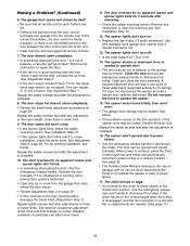
...(Adjustment Step 1). See Adjustment Step 2. • If the door opens at least 5 feet (1.5 m), the travel limits adjustment procedures on the wire between the door control and the motor unit. • Clear memory and re-program all remote controls. 7. Repeat the safety reverse test after...is unbalanced or binding, call a trained door systems technician. Repeat the safety reverse test after reversing: • Check the safety reversing sensor. Turn it is normal for use the emergency release handle to force or travel while being supported entirely by itself: • Be ...
...(Adjustment Step 1). See Adjustment Step 2. • If the door opens at least 5 feet (1.5 m), the travel limits adjustment procedures on the wire between the door control and the motor unit. • Clear memory and re-program all remote controls. 7. Repeat the safety reverse test after...is unbalanced or binding, call a trained door systems technician. Repeat the safety reverse test after reversing: • Check the safety reversing sensor. Turn it is normal for use the emergency release handle to force or travel while being supported entirely by itself: • Be ...

1355 Manual
Page 37
... Header bracket w/clevis pin & fastener 8 41A5047 Door bracket w/clevis pin & fastener 9 41A5034 Safety sensor kit (receiving and sending eyes) with 3' (.9 m) 2-conductor bell wire attached 10 178B34 Straight door arm section 11 178B35 Curved door arm section 12 41A5266-1 Safety sensor brackets (2) Not shown 41A2770-6 Installation hardware bag (see page 7). 114A3072 Owner's manual 114A3072SP...
... Header bracket w/clevis pin & fastener 8 41A5047 Door bracket w/clevis pin & fastener 9 41A5034 Safety sensor kit (receiving and sending eyes) with 3' (.9 m) 2-conductor bell wire attached 10 178B34 Straight door arm section 11 178B35 Curved door arm section 12 41A5266-1 Safety sensor brackets (2) Not shown 41A2770-6 Installation hardware bag (see page 7). 114A3072 Owner's manual 114A3072SP...
1355 Manual
Page 38
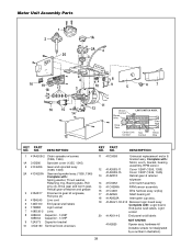
...Contact Contact Yellow Wire KEY PART NO. hardware kit (includes screws not designated by a number in illustration). 38 Complete with : Motor, worm, bracket, bearing assembly, RPM sensor. 12 41A3583-11 41A3583-15 13 41A2818 Cover 1/2HP (1356, 1355) Cover 1/3HP (1346, 1345) Helical gear ...& retainer w/grease 14 41D3452 Limit switch asembly 15 41C4398A RPM sensor assembly 16 41C4246 Wire harness assy.
...Contact Contact Yellow Wire KEY PART NO. hardware kit (includes screws not designated by a number in illustration). 38 Complete with : Motor, worm, bracket, bearing assembly, RPM sensor. 12 41A3583-11 41A3583-15 13 41A2818 Cover 1/2HP (1356, 1355) Cover 1/3HP (1346, 1345) Helical gear ...& retainer w/grease 14 41D3452 Limit switch asembly 15 41C4398A RPM sensor assembly 16 41C4246 Wire harness assy.


