1355 Manual
Page 1
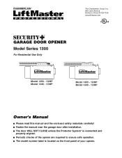
The Chamberlain Group, Inc. 845 Larch Avenue Elmhurst, Illinois 60126-1196 www.liftmaster.com ® GARAGE DOOR OPENER Model Series 1300 For Residential Use Only Model 1356 - 1/2HP Model 1346 - 1/3HP Model 1355 - 1/2HP Model 1345 - 1/3HP Owner's Manual ■ Please read this manual and the enclosed safety materials carefully! ■ Fasten the manual...
The Chamberlain Group, Inc. 845 Larch Avenue Elmhurst, Illinois 60126-1196 www.liftmaster.com ® GARAGE DOOR OPENER Model Series 1300 For Residential Use Only Model 1356 - 1/2HP Model 1346 - 1/3HP Model 1355 - 1/2HP Model 1345 - 1/3HP Owner's Manual ■ Please read this manual and the enclosed safety materials carefully! ■ Fasten the manual...
1355 Manual
Page 2
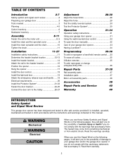
... Motor unit assembly parts 38 Accessories 39 Repair Parts and Service 40 Warranty 40 INTRODUCTION Safety Symbol and Signal Word Review This garage door opener has been designed and tested to offer safe service provided it . TABLE OF CONTENTS Introduction 2-7 Safety symbol and signal word review 2 ... the header bracket location 12-13 Install the header bracket 14 Attach the rail to the header bracket 15 Position the opener 16 Hang the opener 17 Install the door control 18 Install the light and lens 19 Attach the emergency release rope and handle .......19 Electrical...
... Motor unit assembly parts 38 Accessories 39 Repair Parts and Service 40 Warranty 40 INTRODUCTION Safety Symbol and Signal Word Review This garage door opener has been designed and tested to offer safe service provided it . TABLE OF CONTENTS Introduction 2-7 Safety symbol and signal word review 2 ... the header bracket location 12-13 Install the header bracket 14 Attach the rail to the header bracket 15 Position the opener 16 Hang the opener 17 Install the door control 18 Install the light and lens 19 Attach the emergency release rope and handle .......19 Electrical...

1355 Manual
Page 3
CAUTION To prevent damage to garage door and opener: • ALWAYS disable locks BEFORE installing and operating the opener. • ONLY operate garage door opener at 120V, 60 Hz to make sure your door binds, sticks, or is out of balance. An unbalanced garage door may ... and remove ALL ropes connected to WARNING garage door BEFORE installing and operating garage door opener to loosen, move or adjust garage door, door springs, cables, pulleys, brackets or their hardware, all of the opener, instructions will call a trained door systems technician. Carpenter's Level (Optional) 12 Tape...
CAUTION To prevent damage to garage door and opener: • ALWAYS disable locks BEFORE installing and operating the opener. • ONLY operate garage door opener at 120V, 60 Hz to make sure your door binds, sticks, or is out of balance. An unbalanced garage door may ... and remove ALL ropes connected to WARNING garage door BEFORE installing and operating garage door opener to loosen, move or adjust garage door, door springs, cables, pulleys, brackets or their hardware, all of the opener, instructions will call a trained door systems technician. Carpenter's Level (Optional) 12 Tape...
1355 Manual
Page 4
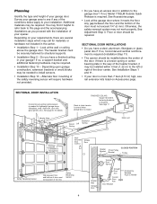
... Wall Torsion OR Spring Extension Spring Motor unit Safety Reversing Sensor --- --- -- is normal when garage door is required (Installation Step 11). • The opener should be needed for lightweight garage doors (fiberglass, steel, aluminum, door with the installation of the door. Alternate floor mounting of the safety reversing sensor... hardware not included in the way of door must not exceed 1/4" (6 mm). Floor or door should be installed within 4 feet (1.22 m) to your opener. Survey your garage area to see rail extension kits listed on your garage door.
... Wall Torsion OR Spring Extension Spring Motor unit Safety Reversing Sensor --- --- -- is normal when garage door is required (Installation Step 11). • The opener should be needed for lightweight garage doors (fiberglass, steel, aluminum, door with the installation of the door. Alternate floor mounting of the safety reversing sensor... hardware not included in the way of door must not exceed 1/4" (6 mm). Floor or door should be installed within 4 feet (1.22 m) to your opener. Survey your garage area to see rail extension kits listed on your garage door.
1355 Manual
Page 6
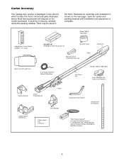
Model 1355 & 1345 ONLY Lighted Door Control Button w/6ABx1-1/2" screws SECURITY✚® Single-Button Remote Control (1) Sprocket Cover Remote Control Transmitter Visor Clip Chain Styrofoam Motor Unit ... the carton and packing material until installation and adjustment is missing, carefully check the packing material. If anything is complete. Carton Inventory Your garage door opener is packaged in the foam. Parts may be stuck in two cartons which contain the motor unit and all parts illustrated below. Note that accessories...
Model 1355 & 1345 ONLY Lighted Door Control Button w/6ABx1-1/2" screws SECURITY✚® Single-Button Remote Control (1) Sprocket Cover Remote Control Transmitter Visor Clip Chain Styrofoam Motor Unit ... the carton and packing material until installation and adjustment is missing, carefully check the packing material. If anything is complete. Carton Inventory Your garage door opener is packaged in the foam. Parts may be stuck in two cartons which contain the motor unit and all parts illustrated below. Note that accessories...
1355 Manual
Page 8
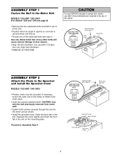
...Unit MODELS 1355 AND 1345 ONLY (For Models 1356 and 1346 see page 9) • Remove the two washered bolts mounted in top of motor unit. • Position rail at an angle to opener so one hole ...AND SIZE BOLT Washered Bolt 5/16"-18x1/2" Rail Hole Styrofoam ASSEMBLY STEP 2 Attach the Chain to door opener. • Align rail and styrofoam over the sprocket. CAUTION: Use only the bolt previously removed from .... Squeeze the cover slightly and insert the front tab in the slot. Proceed to garage door opener, use ONLY those bolts/fasteners mounted in the top of the washered bolts part way in. ...
...Unit MODELS 1355 AND 1345 ONLY (For Models 1356 and 1346 see page 9) • Remove the two washered bolts mounted in top of motor unit. • Position rail at an angle to opener so one hole ...AND SIZE BOLT Washered Bolt 5/16"-18x1/2" Rail Hole Styrofoam ASSEMBLY STEP 2 Attach the Chain to door opener. • Align rail and styrofoam over the sprocket. CAUTION: Use only the bolt previously removed from .... Squeeze the cover slightly and insert the front tab in the slot. Proceed to garage door opener, use ONLY those bolts/fasteners mounted in the top of the washered bolts part way in. ...
1355 Manual
Page 9
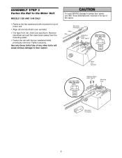
Use only these bolts! WARNING CAUTION To avoid SERIOUS damage to garage door opener, use ONLY those bolts/fasteners mounted in top of motor unit. • Align rail and styrofoam over sprocket. • Cut tape from the mounting plate). &#... STEP 3 Fasten the Rail to the Motor Unit MODELS 1356 AND 1346 ONLY • Remove the two washered bolts mounted in the top of the opener. Remove styrofoam and pull the chain back (away from rail, chain and styrofoam. Use of any other bolts will cause serious damage to door...
Use only these bolts! WARNING CAUTION To avoid SERIOUS damage to garage door opener, use ONLY those bolts/fasteners mounted in top of motor unit. • Align rail and styrofoam over sprocket. • Cut tape from the mounting plate). &#... STEP 3 Fasten the Rail to the Motor Unit MODELS 1356 AND 1346 ONLY • Remove the two washered bolts mounted in the top of the opener. Remove styrofoam and pull the chain back (away from rail, chain and styrofoam. Use of any other bolts will cause serious damage to door...
1355 Manual
Page 10
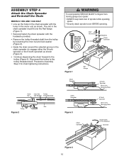
... ONLY • Line up the holes in the chain spreader with the hardware provided. • Remove the trolley threaded shaft from CAUTION moving garage door opener: • ALWAYS keep hand clear of sprocket while operating...
... ONLY • Line up the holes in the chain spreader with the hardware provided. • Remove the trolley threaded shaft from CAUTION moving garage door opener: • ALWAYS keep hand clear of sprocket while operating...

1355 Manual
Page 11
... repairs to cables, spring assemblies and other hardware MUST be caught in plain view on inside of the door. 10. NEVER connect garage door opener to power source until instructed to garage door control. 11. Door MUST reverse on wall next to do not re-adjust the chain. ASSEMBLY ...its midpoint, re-tighten Chain the inner nut to avoid entanglement. 5. Disable all locks and remove all ropes connected to garage door BEFORE installing opener to secure the adjustment. To Tighten Inner Nut • To tighten the chain, turn outer nut in SEVERE INJURY or DEATH. 3. Install garage ...
... repairs to cables, spring assemblies and other hardware MUST be caught in plain view on inside of the door. 10. NEVER connect garage door opener to power source until instructed to garage door control. 11. Door MUST reverse on wall next to do not re-adjust the chain. ASSEMBLY ...its midpoint, re-tighten Chain the inner nut to avoid entanglement. 5. Disable all locks and remove all ropes connected to garage door BEFORE installing opener to secure the adjustment. To Tighten Inner Nut • To tighten the chain, turn outer nut in SEVERE INJURY or DEATH. 3. Install garage ...

1355 Manual
Page 12
... 1 Determine the Header Bracket Location WARNING To prevent possible SERIOUS INJURY or DEATH: CAUTION • Header bracket MUST be RIGIDLY fastened to Step 2, page 14. Open your door.
... 1 Determine the Header Bracket Location WARNING To prevent possible SERIOUS INJURY or DEATH: CAUTION • Header bracket MUST be RIGIDLY fastened to Step 2, page 14. Open your door.

1355 Manual
Page 13
.... If headroom clearance is minimal, you need to page 14 for ceiling installation. Close the door and mark the inside vertical centerline of the door. Open your door to the highest point of travel ) to floor . . . . .92" (234 cm) Actual height of inches exceeds the height available in your garage door...
.... If headroom clearance is minimal, you need to page 14 for ceiling installation. Close the door and mark the inside vertical centerline of the door. Open your door to the highest point of travel ) to floor . . . . .92" (234 cm) Actual height of inches exceeds the height available in your garage door...

1355 Manual
Page 15
Have someone hold the opener securely on a temporary support to allow the rail to clear the spring. • Position the rail bracket against the header bracket. • Align the bracket ... ACTUAL SIZE Clevis Pin 5/16"x2-3/4" 15 Ring Fastener Use packing material as shown. • Insert a ring fastener to the Header Bracket • Position the opener on the garage floor below the header bracket. Header Wall Header Bracket Chain Pulley Bracket INSTALLATION STEP 3 Attach the Rail to secure.
Have someone hold the opener securely on a temporary support to allow the rail to clear the spring. • Position the rail bracket against the header bracket. • Align the bracket ... ACTUAL SIZE Clevis Pin 5/16"x2-3/4" 15 Ring Fastener Use packing material as shown. • Insert a ring fastener to the Header Bracket • Position the opener on the garage floor below the header bracket. Header Wall Header Bracket Chain Pulley Bracket INSTALLATION STEP 3 Attach the Rail to secure.
1355 Manual
Page 16
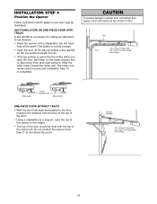
... on top section of door. Rail Door 2x4 is completed. ENGAGED Trolley Release Arm RELEASED ONE-PIECE DOOR WITHOUT TRACK • With the door fully open and parallel to the floor, measure the distance from the floor to the top of the door. • Using a stepladder as illustrated. Slide the ...outer trolley toward the motor unit. WARNING CAUTION To prevent damage to garage door, rest garage door opener rail on 2x4 placed on the trolley release arm to this height. • The top of the door should be level with the top of...
... on top section of door. Rail Door 2x4 is completed. ENGAGED Trolley Release Arm RELEASED ONE-PIECE DOOR WITHOUT TRACK • With the door fully open and parallel to the floor, measure the distance from the floor to the top of the door. • Using a stepladder as illustrated. Slide the ...outer trolley toward the motor unit. WARNING CAUTION To prevent damage to garage door, rest garage door opener rail on 2x4 placed on the trolley release arm to this height. • The top of the door should be level with the top of...
1355 Manual
Page 17
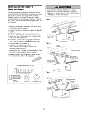
... hanging bracket to make sure the rail is not centered above the door). 7. Grease the top and underside of the garage. Fasten the opener to structural supports of the rail surface where the trolley slides with 5/16"-18x7/8" hex bolts, lock washers and nuts. 6. Concrete anchors ... To avoid possible SERIOUS INJURY from each bracket to provide rigid support. Remove the 2x4. Measure the distance from a falling CAUTION garage door opener, fasten it SECURELY to the hanging brackets with rail grease. Yours may be used if installing any brackets into masonry. On finished ceilings (...
... hanging bracket to make sure the rail is not centered above the door). 7. Grease the top and underside of the garage. Fasten the opener to structural supports of the rail surface where the trolley slides with 5/16"-18x7/8" hex bolts, lock washers and nuts. 6. Concrete anchors ... To avoid possible SERIOUS INJURY from each bracket to provide rigid support. Remove the 2x4. Measure the distance from a falling CAUTION garage door opener, fasten it SECURELY to the hanging brackets with rail grease. Yours may be used if installing any brackets into masonry. On finished ceilings (...
1355 Manual
Page 18
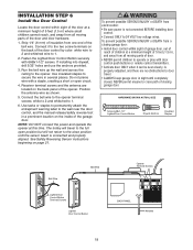
...use the anchors provided. 3. Run the bell wire up the wall and across the ceiling to 1. 6. Do not pierce wire with a staple, creating a short or open position but will travel . • ALWAYS keep garage door in sight until the sensor beam is connected and properly aligned. Position the antenna wire as...when it to the two screw terminals on the back panel of the bell wire. Connect the bell wire to the opener terminal screws: white to 2 and white/red to the opener. NEVER permit anyone to cross path of closing garage door: • Install door control within sight of the door ...
...use the anchors provided. 3. Run the bell wire up the wall and across the ceiling to 1. 6. Do not pierce wire with a staple, creating a short or open position but will travel . • ALWAYS keep garage door in sight until the sensor beam is connected and properly aligned. Position the antenna wire as...when it to the two screw terminals on the back panel of the bell wire. Connect the bell wire to the opener terminal screws: white to 2 and white/red to the opener. NEVER permit anyone to cross path of closing garage door: • Install door control within sight of the door ...
1355 Manual
Page 19
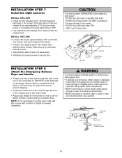
.... Light Bulb INSTALLATION STEP 8 Attach the Emergency Release Rope and Handle • Thread one end of the rope through the hole in the top of opener front panel. • Position lens against panel with an overhand knot at least 1" (2.5 cm) from a CAUTION falling garage door: • If ... neck or specialty light bulbs. • DO NOT use handle to prevent unraveling. WARNING CAUTION To prevent possible OVERHEATING of the rope to the opener: • DO NOT use bulbs larger than 75W. • ONLY use emergency release handle to secure lens. Secure with a match or lighter...
.... Light Bulb INSTALLATION STEP 8 Attach the Emergency Release Rope and Handle • Thread one end of the rope through the hole in the top of opener front panel. • Position lens against panel with an overhand knot at least 1" (2.5 cm) from a CAUTION falling garage door: • If ... neck or specialty light bulbs. • DO NOT use handle to prevent unraveling. WARNING CAUTION To prevent possible OVERHEATING of the rope to the opener: • DO NOT use bulbs larger than 75W. • ONLY use emergency release handle to secure lens. Secure with a match or lighter...
1355 Manual
Page 20
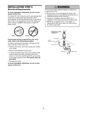
... Wire Black Wire White Wire Black Wire 20 To make it fit outlet. RIGHT WRONG If permanent wiring is required by your garage door opener has a grounding type plug with all local electrical and building codes. • NEVER use an extension cord, 2-wire adapter, or change...local code, refer to the screw on the silver terminal; INSWTAALRLNAITNIOGN STEP 9 Electrical Requirements CAUTION To avoid installation difficulties, do not run the opener at this time. This plug will only fit into the outlet you have, contact a qualified electrician to the green ground screw. If the ...
... Wire Black Wire White Wire Black Wire 20 To make it fit outlet. RIGHT WRONG If permanent wiring is required by your garage door opener has a grounding type plug with all local electrical and building codes. • NEVER use an extension cord, 2-wire adapter, or change...local code, refer to the screw on the silver terminal; INSWTAALRLNAITNIOGN STEP 9 Electrical Requirements CAUTION To avoid installation difficulties, do not run the opener at this time. This plug will only fit into the outlet you have, contact a qualified electrician to the green ground screw. If the ...

1355 Manual
Page 21
...the door is not connected to the receiving eye (with an amber indicator light) transmits an invisible light beam to the garage door CAUTION opener BEFORE installing the safety reversing sensor. WARNING Be sure power is closing . Extension brackets (see accessories) are designed to avoid drilling extra ... connected and aligned, the sensor will move in masonry if repositioning is closing , the door will stop and reverse to full open position, and the opener lights will flash 10 times. Either can be installed on the wall, the brackets must be installed inside the garage 21 Safety...
...the door is not connected to the receiving eye (with an amber indicator light) transmits an invisible light beam to the garage door CAUTION opener BEFORE installing the safety reversing sensor. WARNING Be sure power is closing . Extension brackets (see accessories) are designed to avoid drilling extra ... connected and aligned, the sensor will move in masonry if repositioning is closing , the door will stop and reverse to full open position, and the opener lights will flash 10 times. Either can be installed on the wall, the brackets must be installed inside the garage 21 Safety...

1355 Manual
Page 22
... at each side of the door, no higher than 6" (15 cm) above the floor. • Carefully measure and place right and left assemblies to the opener is recommended. Garage door track installation (preferred): • Slip the curved arms over the rounded edge of the track. INSTALLING THE BRACKETS Be sure power...
... at each side of the door, no higher than 6" (15 cm) above the floor. • Carefully measure and place right and left assemblies to the opener is recommended. Garage door track installation (preferred): • Slip the curved arms over the rounded edge of the track. INSTALLING THE BRACKETS Be sure power...

1355 Manual
Page 23
...indicator lights in the receiving eye is off, dim, or flickering (and the invisible light beam path is not obstructed), alignment is already open wire to the opener. Figure 5 Wing Nut 1/4"-20 Carriage Bolt 1/4"-20x1/2" Lens TROUBLESHOOTING THE SAFETY REVERSING SENSORS 1. These can be heard.) See page 21. ...wing nut and adjust sensor until it will reverse. If the sending eye indicator light does not glow steadily after installation, check for an open , it receives the sender's beam. If the receiving eye indicator light is closing, the door will not close. MOUNTING AND WIRING ...
...indicator lights in the receiving eye is off, dim, or flickering (and the invisible light beam path is not obstructed), alignment is already open wire to the opener. Figure 5 Wing Nut 1/4"-20 Carriage Bolt 1/4"-20x1/2" Lens TROUBLESHOOTING THE SAFETY REVERSING SENSORS 1. These can be heard.) See page 21. ...wing nut and adjust sensor until it will reverse. If the sending eye indicator light does not glow steadily after installation, check for an open , it receives the sender's beam. If the receiving eye indicator light is closing, the door will not close. MOUNTING AND WIRING ...


