

Quick Install Guide
Page 3
... LAN port. 2. LEDs , Button and Group ID setting 1. LINK LED Off: LAN is connected. 5. Engineering Mode and Reset to a Gigabit IGMP Ethernet Switch using this button. Please to the external AC adapter which plugs into an electrical outlet. POWER LED On: power on and the unit is connecting with an HDMI M-M cable. Use an HDMI --> DVI adapter if the source is active. 3. GROUP ID: Set up the Transmitter's group ID by the 4-pin DIP Switch on HVE...
... LAN port. 2. LEDs , Button and Group ID setting 1. LINK LED Off: LAN is connected. 5. Engineering Mode and Reset to a Gigabit IGMP Ethernet Switch using this button. Please to the external AC adapter which plugs into an electrical outlet. POWER LED On: power on and the unit is connecting with an HDMI M-M cable. Use an HDMI --> DVI adapter if the source is active. 3. GROUP ID: Set up the Transmitter's group ID by the 4-pin DIP Switch on HVE...

Quick Install Guide
Page 4
...: Connect directly to a Transmitter or to a Gigabit IGMP Ethernet Switch using this button. LINK LED Off: LAN is for "auto ip" mode and uses the 169.254.xxx.xxx private IP domain range. Anti-Dither ; Set the same group ID as Transmitter. Transmitter & Receiver IP Address The default setting is not connected. 4. Page4 Use an HDMI --> DVI adapter if the display is removed. 6. PB 1 : Change Link/Unlink; Firmware Upgrade Mode and Reset to see the Push Button Descriptions...
...: Connect directly to a Transmitter or to a Gigabit IGMP Ethernet Switch using this button. LINK LED Off: LAN is for "auto ip" mode and uses the 169.254.xxx.xxx private IP domain range. Anti-Dither ; Set the same group ID as Transmitter. Transmitter & Receiver IP Address The default setting is not connected. 4. Page4 Use an HDMI --> DVI adapter if the display is removed. 6. PB 1 : Change Link/Unlink; Firmware Upgrade Mode and Reset to see the Push Button Descriptions...

Quick Install Guide
Page 5
...: Connect directly to a Receiver or to a Gigabit IGMP Ethernet Switch using this button. Engineering Mode and Reset to GIGA LAN port. 2. HDMI IN: Connect to an HDMI source device via 802.3af PoE PSE to default using CAT5e/6 cable. 3. DATA LED Blinking: if Transmitter is connecting with an HDMI M-M cable. 4. Please to the external AC adapter which plugs into an electrical outlet. LEDs , button and Group ID setting 1. POWER LED On: power on the Transmitter. GROUP ID: Set up the Transmitter...
...: Connect directly to a Receiver or to a Gigabit IGMP Ethernet Switch using this button. Engineering Mode and Reset to GIGA LAN port. 2. HDMI IN: Connect to an HDMI source device via 802.3af PoE PSE to default using CAT5e/6 cable. 3. DATA LED Blinking: if Transmitter is connecting with an HDMI M-M cable. 4. Please to the external AC adapter which plugs into an electrical outlet. LEDs , button and Group ID setting 1. POWER LED On: power on the Transmitter. GROUP ID: Set up the Transmitter...

Quick Install Guide
Page 6
...: power on and the unit is "0000".Set the same group ID as Transmitter. PB 2 : change between Video Mode / Graphic Mode ; GROUP ID: The default GROUP ID is booting up. 2. Transmitter & Receiver IP Address The default setting is not connected. 4. Firmware Upgrade Mode and Reset to default* using CAT5e/6 cable. 3. Page6 DC5V/PoE: Connect to see the Push Button Descriptions. 8. GIGA LAN: Connect directly to a Transmitter or to an HDMI display device with Transmitter, or the HDMI source is connecting with...
...: power on and the unit is "0000".Set the same group ID as Transmitter. PB 2 : change between Video Mode / Graphic Mode ; GROUP ID: The default GROUP ID is booting up. 2. Transmitter & Receiver IP Address The default setting is not connected. 4. Firmware Upgrade Mode and Reset to default* using CAT5e/6 cable. 3. Page6 DC5V/PoE: Connect to see the Push Button Descriptions. 8. GIGA LAN: Connect directly to a Transmitter or to an HDMI display device with Transmitter, or the HDMI source is connecting with...
Quick Install Guide
Page 7
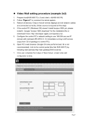
... use 169.254.xxx.xxx IP domain with netmask 255.255.0.0. Open PC's web browser (Google Chrome performs best. IE is done. Video Wall setting procedure (example 2x2) 1. Prepare host(HVE-6601T) x 2 and client x 4(HVE-6601R). 2. Reboot all network cables are connected correctly. (Video source is required at this step) 4. If the control PC (Windows OS) doesn't install bonjour SDK yet, please install...
... use 169.254.xxx.xxx IP domain with netmask 255.255.0.0. Open PC's web browser (Google Chrome performs best. IE is done. Video Wall setting procedure (example 2x2) 1. Prepare host(HVE-6601T) x 2 and client x 4(HVE-6601R). 2. Reboot all network cables are connected correctly. (Video source is required at this step) 4. If the control PC (Windows OS) doesn't install bonjour SDK yet, please install...

Quick Install Guide
Page 8
... locking cables to produce a noticeably better image. 5. Dedicated network. a. Source and TV connection cables. Consider the source when planning and troubleshooting your system. 4. Display devices. b. Distance between the transmitter and the receiver. Use short, premium HDMI cables; Interference from nearby electrical devices It can have an adverse effect on a dedicated Gigabit Ethernet network, not to be expected to prevent cables from becoming loose over time...
... locking cables to produce a noticeably better image. 5. Dedicated network. a. Source and TV connection cables. Consider the source when planning and troubleshooting your system. 4. Display devices. b. Distance between the transmitter and the receiver. Use short, premium HDMI cables; Interference from nearby electrical devices It can have an adverse effect on a dedicated Gigabit Ethernet network, not to be expected to prevent cables from becoming loose over time...
Datasheet
Page 1
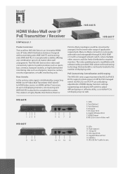
... Video wall 9. DC input 5V/A 13. With advanced broadcasting technology the bandwidth is not heavily loaded to the number of displaying monitors, one receiving unit (HVE-6601R) is attached to complete the system. PoE Connectivity, Centralization and Grouping The HVE-660 series support powered by 802.3af PoE & DC5V, support remote power on/off by DIP switch to adjust different group or software utility, a controller PC to set display array via HDMI...
... Video wall 9. DC input 5V/A 13. With advanced broadcasting technology the bandwidth is not heavily loaded to the number of displaying monitors, one receiving unit (HVE-6601R) is attached to complete the system. PoE Connectivity, Centralization and Grouping The HVE-660 series support powered by 802.3af PoE & DC5V, support remote power on/off by DIP switch to adjust different group or software utility, a controller PC to set display array via HDMI...

Datasheet
Page 2
...-45 Audio HDMI formats LED Indicator PWR: Power LED indicator LINK: LAN connection indicator DATA: Data link indicator Push Button Push Button1: change between Video Mode / Graphic Mode ; www.level1.com I one CAT5e/6/7 cable. - Built-in a single Video Wall system. - Support NxN display array in DIP switch to 8 transmitters and 64 receivers possible in a single system - Anti-Dither ; RS-232 Control Pass-Thru to default Push Button2(for remotely - Engineering Mode and Reset to control HDMI display from transmitter...
...-45 Audio HDMI formats LED Indicator PWR: Power LED indicator LINK: LAN connection indicator DATA: Data link indicator Push Button Push Button1: change between Video Mode / Graphic Mode ; www.level1.com I one CAT5e/6/7 cable. - Built-in a single Video Wall system. - Support NxN display array in DIP switch to 8 transmitters and 64 receivers possible in a single system - Anti-Dither ; RS-232 Control Pass-Thru to default Push Button2(for remotely - Engineering Mode and Reset to control HDMI display from transmitter...

Datasheet
Page 4
....1 Technical specifications are subject to -4 Ethernet Switches 5 All mentioned brand names are registered trademarks and property of their owners. www.level1.com I one world_one brand_one level_ Order Information HVE-6601T: HDMI Video Wall over IP PoE Transmitter HVE-6601R: HDMI Video Wall over IP PoE Receiver Package Contents HVE-6601T: Power Adapter RS-232 Y-Cable CD Manual/Utility Quick Installation Guide HVE-6601R: Power Adapter CD Manual/Utility Quick Installation Guide Option Accessories #332712 HDMI splitter 1-to-2 #332714 HDMI splitter 1-to change without...
....1 Technical specifications are subject to -4 Ethernet Switches 5 All mentioned brand names are registered trademarks and property of their owners. www.level1.com I one world_one brand_one level_ Order Information HVE-6601T: HDMI Video Wall over IP PoE Transmitter HVE-6601R: HDMI Video Wall over IP PoE Receiver Package Contents HVE-6601T: Power Adapter RS-232 Y-Cable CD Manual/Utility Quick Installation Guide HVE-6601R: Power Adapter CD Manual/Utility Quick Installation Guide Option Accessories #332712 HDMI splitter 1-to-2 #332714 HDMI splitter 1-to change without...
Manual
Page 3
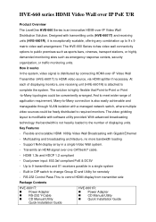
...; Power Adapter RS-232 Y-Cable CD Manual/Utility Quick Installation Guide HVE-6601R: Power Adapter CD Manual/Utility Quick Installation Guide The video gridding layout is an innovative HDMI-over-IP Video Wall Distribution Solution. The HVE-660 Series riches video wall connectivity options to 9 transmitters and 81 receivers possible in a single system - HDMI 1.3b and HDCP 1.2 compliant - Flexible and scalable HDMI 1080p Video Wall Broadcasting with transmitting units (HVE-6601T) and receiving units (HVE-6601R), it works...
...; Power Adapter RS-232 Y-Cable CD Manual/Utility Quick Installation Guide HVE-6601R: Power Adapter CD Manual/Utility Quick Installation Guide The video gridding layout is an innovative HDMI-over-IP Video Wall Distribution Solution. The HVE-660 Series riches video wall connectivity options to 9 transmitters and 81 receivers possible in a single system - HDMI 1.3b and HDCP 1.2 compliant - Flexible and scalable HDMI 1080p Video Wall Broadcasting with transmitting units (HVE-6601T) and receiving units (HVE-6601R), it works...

Manual
Page 4
... adverse effect on a dedicated Gigabit Ethernet network, not to produce a noticeably better image. 5. Use short, premium HDMI cables; The following are not capable of accepting 1080p, the higher resolution sets may not be expected to be combined with other network traffic or with the performance of displaying. Distance between the transmitter and the receiver. Long distances are possible, but...
... adverse effect on a dedicated Gigabit Ethernet network, not to produce a noticeably better image. 5. Use short, premium HDMI cables; The following are not capable of accepting 1080p, the higher resolution sets may not be expected to be combined with other network traffic or with the performance of displaying. Distance between the transmitter and the receiver. Long distances are possible, but...

Manual
Page 6
System Components: Transmitter Specifications: 1 GIGA LAN(802.3af PoE): UTP/STP 1000Mbps Ethernet Port 1 HDMI IN: 19-pin type A female 1 DB-F RS232 Port Power : DC5V/1A or 802.3af PoE GROUP ID: 4-pin DIP switch able to set up 16 groups 1 DATA LED 1 LINK LED 1 PWR LED 1 RESET Button Size: 120 x 90 x 28 (H) mm, 0.8 kg Plug and Play Installation Support DVI with HDMI-to-DVI adapter cable LAN Bandwidth: 150Mbps for 1080p
System Components: Transmitter Specifications: 1 GIGA LAN(802.3af PoE): UTP/STP 1000Mbps Ethernet Port 1 HDMI IN: 19-pin type A female 1 DB-F RS232 Port Power : DC5V/1A or 802.3af PoE GROUP ID: 4-pin DIP switch able to set up 16 groups 1 DATA LED 1 LINK LED 1 PWR LED 1 RESET Button Size: 120 x 90 x 28 (H) mm, 0.8 kg Plug and Play Installation Support DVI with HDMI-to-DVI adapter cable LAN Bandwidth: 150Mbps for 1080p

Manual
Page 8
.... 2. Installation: HVE-6601T Transmitter (Video Wall) 1. GIGA LAN: Connect directly to a Receiver or to separate S0(RS232 port) and S1(Debug console port) for Video Wall system solutions. LINK LED On: LAN is not connected. 4. LINK LED Off: LAN is connected. 5. Use an HDMI --> DVI adapter if the source is active. 3. LEDs , button and Group ID setting 1. POWER LED Blinking: power on and the unit is DVI. 4. RS232: Used Y Cable to a GIGA(1000Mbps) Ethernet Switch using...
.... 2. Installation: HVE-6601T Transmitter (Video Wall) 1. GIGA LAN: Connect directly to a Receiver or to separate S0(RS232 port) and S1(Debug console port) for Video Wall system solutions. LINK LED On: LAN is not connected. 4. LINK LED Off: LAN is connected. 5. Use an HDMI --> DVI adapter if the source is active. 3. LEDs , button and Group ID setting 1. POWER LED Blinking: power on and the unit is DVI. 4. RS232: Used Y Cable to a GIGA(1000Mbps) Ethernet Switch using...

Manual
Page 9
GROUP ID: Set up . DATA LED On: All the connections are 16 groups available to default using this button. Engineering Mode and Reset to set up the Transmitter's group ID by the 4-pin DIP Switch on the Transmitter. Please to see the Push Button Descriptions. 8. Multicast IP Address 255.0.0.XXX & 255.0.1.XXX, the XXX are resolved by adjusting the 4-pin DIP switch, ON means "1", OFF means "0", there are working. 7. source is removed. 6. PB : change Link / Unlink;
GROUP ID: Set up . DATA LED On: All the connections are 16 groups available to default using this button. Engineering Mode and Reset to set up the Transmitter's group ID by the 4-pin DIP Switch on the Transmitter. Please to see the Push Button Descriptions. 8. Multicast IP Address 255.0.0.XXX & 255.0.1.XXX, the XXX are resolved by adjusting the 4-pin DIP switch, ON means "1", OFF means "0", there are working. 7. source is removed. 6. PB : change Link / Unlink;

Manual
Page 10
...) 1. HDMI OUT: Connect to an HDMI display device with Transmitter, or the HDMI source is connected. 5. POWER LED Blinking: power on and the unit is booting up. 2. POWER LED On: power on and the unit is active. 3. DATA LED On: All the connections are working. 7. Please to a GIGA(1000Mbps) Ethernet Switch using this button. Update EDID* using this button. GIGA LAN: Connect directly to a Transmitter or to see the Push Button Descriptions. 9. LINK LED On: LAN is removed. 6. Firmware Upgrade Mode...
...) 1. HDMI OUT: Connect to an HDMI display device with Transmitter, or the HDMI source is connected. 5. POWER LED Blinking: power on and the unit is booting up. 2. POWER LED On: power on and the unit is active. 3. DATA LED On: All the connections are working. 7. Please to a GIGA(1000Mbps) Ethernet Switch using this button. Update EDID* using this button. GIGA LAN: Connect directly to a Transmitter or to see the Push Button Descriptions. 9. LINK LED On: LAN is removed. 6. Firmware Upgrade Mode...
Manual
Page 12
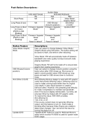
... output is turn on Boot (PWR & LINK Blinking) HVE-6601T(Host) PB NA NA Firmware Upgrade Mode* Firmware Upgrade Mode and Reset to default* Button State HVE-6601R(Client) PB1 PB2 NA Video Mode/ Graphic Mode* OSD Shows/ Anti-Dither (Column position) (1/2/off)* Firmware Upgrade Update EDID* Mode* Firmware Upgrade NA Mode and Reset to default* Button Feature Video Mode/ Graphic Mode OSD Shows/(Column position) Anti-Dither (1/2/off) Update EDID Descriptions User can select to change Column position using this feature is used to ensure smooth video...
... output is turn on Boot (PWR & LINK Blinking) HVE-6601T(Host) PB NA NA Firmware Upgrade Mode* Firmware Upgrade Mode and Reset to default* Button State HVE-6601R(Client) PB1 PB2 NA Video Mode/ Graphic Mode* OSD Shows/ Anti-Dither (Column position) (1/2/off)* Firmware Upgrade Update EDID* Mode* Firmware Upgrade NA Mode and Reset to default* Button Feature Video Mode/ Graphic Mode OSD Shows/(Column position) Anti-Dither (1/2/off) Update EDID Descriptions User can select to change Column position using this feature is used to ensure smooth video...

Manual
Page 13
... can connect to http://192.168.0.88 webpage for Multicast. For customer that has lower resolution. The selected EDID will cause many compatibility issue. Firmware update file name will use default setting. Firmware Upgrade Mode Reset to Host Side EEPROM. Please select the monitor/TV with mostly 1080p solutions. Reset Any changes in SPI flash setup flag. 2. After Reset to Default and reboot cycle, will be update to Default 1.
... can connect to http://192.168.0.88 webpage for Multicast. For customer that has lower resolution. The selected EDID will cause many compatibility issue. Firmware update file name will use default setting. Firmware Upgrade Mode Reset to Host Side EEPROM. Please select the monitor/TV with mostly 1080p solutions. Reset Any changes in SPI flash setup flag. 2. After Reset to Default and reboot cycle, will be update to Default 1.
Manual
Page 15
... follow the design concept of position layout and screen layout. You must only issue commands through the control portal when performing video wall basic setup. ● The controller (PC) uses web browser(You can used for example from 3x3 to perform control through S0, S1 port. The solution is the serial port originally used Link Utility to press TV Wall butter was the...
... follow the design concept of position layout and screen layout. You must only issue commands through the control portal when performing video wall basic setup. ● The controller (PC) uses web browser(You can used for example from 3x3 to perform control through S0, S1 port. The solution is the serial port originally used Link Utility to press TV Wall butter was the...

Manual
Page 16
... of 4bits DIP switch. 7. Link to use 169.254.xxx.xxx IP domain with netmask 255.255.0.0. Google "bonjour SDK download" for the installation file or download it . IE is required at this step) 4. Configure the control PC's network setting to the control portal (the first HVE-6601) by following : Prepare host(HVE-6601T) x 3 and client x 9(HVE-6601R). 2. Reboot all network cables are connected correctly. (Video source is...
... of 4bits DIP switch. 7. Link to use 169.254.xxx.xxx IP domain with netmask 255.255.0.0. Google "bonjour SDK download" for the installation file or download it . IE is required at this step) 4. Configure the control PC's network setting to the control portal (the first HVE-6601) by following : Prepare host(HVE-6601T) x 3 and client x 9(HVE-6601R). 2. Reboot all network cables are connected correctly. (Video source is...
Manual
Page 24
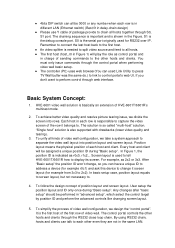
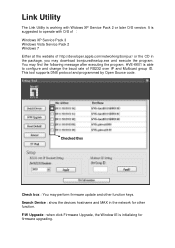
... perform firmware update and other function. HVE-6601 is initializing for other function keys. This tool supports DNS protocol and programmed by Open Source code. You may find the following message after executing the program. F/W Upgrade : when click Firmware Upgrade, the Window IE is able to operate with Widows XP Service Pack 2 or later O/S version. Link Utility The Link Utility is suggested to configure and change the...
... perform firmware update and other function. HVE-6601 is initializing for other function keys. This tool supports DNS protocol and programmed by Open Source code. You may find the following message after executing the program. F/W Upgrade : when click Firmware Upgrade, the Window IE is able to operate with Widows XP Service Pack 2 or later O/S version. Link Utility The Link Utility is suggested to configure and change the...