(English) Rescue and Recovery 4.3 Deployment Guide
Page 10
... that organizations can benefit from the Rescue and Recovery program on select machine types of Lenovo-branded personal computers only. - You can optimize system performance by taking a new incremental... backup to rescue lost data, applications, and operating systems with the 256 AES key. The rejuvenation process helps eliminate viruses, adware and spyware, while maintaining your clients... Helps users access network drives for purchase as a USB hard disk drive. Access BIOS: Opens the BIOS Setup Utility program. Event log: Provides details of recent user activities and listings of...
... that organizations can benefit from the Rescue and Recovery program on select machine types of Lenovo-branded personal computers only. - You can optimize system performance by taking a new incremental... backup to rescue lost data, applications, and operating systems with the 256 AES key. The rejuvenation process helps eliminate viruses, adware and spyware, while maintaining your clients... Helps users access network drives for purchase as a USB hard disk drive. Access BIOS: Opens the BIOS Setup Utility program. Event log: Provides details of recent user activities and listings of...
(English) Rescue and Recovery 4.3 Deployment Guide
Page 65
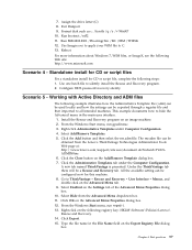
... Template file (.adm) can be used locally and how the settings can be configured now for CD or script file, complete the following registry key: HKLM\Software\Policies\Lenovo\ Rescue and Recovery. 14. Standalone install for CD or script files For a standalone install for this machine. 8. Scenario 5 - Click the Close button on... the drive letter (C) 8. Exit Diskpart 9. Right-click on the Advanced Menu Properties dialog box. 12. Run BMGR32.EXE /Fbootmgr.bin /M1 /IBM /THINK 12. Configure BIOS password recovery silently. 7.
... Template file (.adm) can be used locally and how the settings can be configured now for CD or script file, complete the following registry key: HKLM\Software\Policies\Lenovo\ Rescue and Recovery. 14. Standalone install for CD or script files For a standalone install for this machine. 8. Scenario 5 - Click the Close button on... the drive letter (C) 8. Exit Diskpart 9. Right-click on the Advanced Menu Properties dialog box. 12. Run BMGR32.EXE /Fbootmgr.bin /M1 /IBM /THINK 12. Configure BIOS password recovery silently. 7.
(English) Rescue and Recovery 4.3 Deployment Guide
Page 76
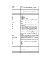
... command-line interface" on the keyboard to enter the Predesktop Area. /TOC tocvalue Set the BIOS TOC location (16 characters that the Master boot record patch program can access. Lenovo-branded preload Only). /OEM Computer is located in the service partition with DOS (dual boot Windows... partition type to set a variable that represent 8 bytes of the Rescue and Recovery program. /Patchn Used for the F11 (default) key press after POST. Table 26. Patchfilefilename Used for installation program only to install the Master boot record patch. /PRTC Used for installation ...
... command-line interface" on the keyboard to enter the Predesktop Area. /TOC tocvalue Set the BIOS TOC location (16 characters that the Master boot record patch program can access. Lenovo-branded preload Only). /OEM Computer is located in the service partition with DOS (dual boot Windows... partition type to set a variable that represent 8 bytes of the Rescue and Recovery program. /Patchn Used for the F11 (default) key press after POST. Table 26. Patchfilefilename Used for installation program only to install the Master boot record patch. /PRTC Used for installation ...
(English) Rescue and Recovery 4.5 Deployment Guide
Page 16
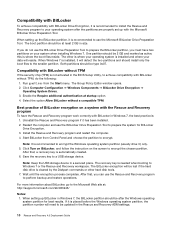
... the Rescue and Recovery program and restart the computer. 4. Note: It is installed and where your data will reside. After that , a recovery key is needed when booting to Windows 7 or the Rescue and Recovery workspace. The Group Policy Editor window opens. 2. Best practice of BitLocker encryption on... system partition, the partition number will need to be lost if the hard disk drive is installed, it will be updated in the BIOS Setup Utility, to achieve compatibility with BitLocker without a compatible TPM. When Windows 7 is cleared by the Diskpart commands or other is...
... the Rescue and Recovery program and restart the computer. 4. Note: It is installed and where your data will reside. After that , a recovery key is needed when booting to Windows 7 or the Rescue and Recovery workspace. The Group Policy Editor window opens. 2. Best practice of BitLocker encryption on... system partition, the partition number will need to be lost if the hard disk drive is installed, it will be updated in the BIOS Setup Utility, to achieve compatibility with BitLocker without a compatible TPM. When Windows 7 is cleared by the Diskpart commands or other is...
(English) Rescue and Recovery 4.5 Deployment Guide
Page 55
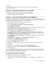
...ADM files The following example illustrates how the Administrative Template file (.adm) can be used for CD or script file, complete the following registry key: HKLM\Software\Policies\Lenovo\Rescue and Recovery. 14. From the Windows Start menu, run regedit. 13. Select Add/Remove Templates. 5. Select Hide from the... Active Directory or LANDesk. Scenario 4 - Go to your intended path in the main user interface. 1. Click OK on the Advanced Menu tab. 9. Configure BIOS password recovery silently. a. Click the Close button on the following steps: 1. 13. Click the Save button.
...ADM files The following example illustrates how the Administrative Template file (.adm) can be used for CD or script file, complete the following registry key: HKLM\Software\Policies\Lenovo\Rescue and Recovery. 14. From the Windows Start menu, run regedit. 13. Select Add/Remove Templates. 5. Select Hide from the... Active Directory or LANDesk. Scenario 4 - Go to your intended path in the main user interface. 1. Click OK on the Advanced Menu tab. 9. Configure BIOS password recovery silently. a. Click the Close button on the following steps: 1. 13. Click the Save button.
(English) Rescue and Recovery 4.5 Deployment Guide
Page 66
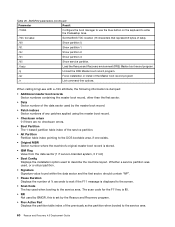
...where the machine's original master boot record is displayed to the screen. • Scan Code The key used to the service area. 60 Rescue and Recovery 4.5 Deployment Guide BMGR32 parameters (continued) Parameter...boot manager to use the blue button on the keyboard to enter the Predesktop Area. /TOC tocvalue Set the BIOS TOC location (16 characters that represent 8 bytes of data). /U0 Show partition 0. /U1 Show partition ...stored. • IBM Flag Value from the data sector (1 if Lenovo-branded system, 0 if not) • Boot Config Displays the installation option used when booting to the...
...where the machine's original master boot record is displayed to the screen. • Scan Code The key used to the service area. 60 Rescue and Recovery 4.5 Deployment Guide BMGR32 parameters (continued) Parameter...boot manager to use the blue button on the keyboard to enter the Predesktop Area. /TOC tocvalue Set the BIOS TOC location (16 characters that represent 8 bytes of data). /U0 Show partition 0. /U1 Show partition ...stored. • IBM Flag Value from the data sector (1 if Lenovo-branded system, 0 if not) • Boot Config Displays the installation option used when booting to the...

BIOS Windows Management Instrumentation Interface Deployment Guide
Page 3
... @Copyright Lenovo 2010 I Security...13 Appendix A. Sample Visual Basic scripts for configuring BIOS settings 15 Restore default settings...15 List all BIOS settings on the local computer 16 Set a single BIOS setting on the local computer 16 Set a single BIOS setting on... exists 17 List all BIOS settings on the remote computer 18 Set a single BIOS setting on a remote computer 18 Set a single BIOS setting on a remote computer when a Administrator password exists 19 Appendix B. Overview ...1 Using Windows Management Instrumentation 1 Key benefits ...1 Function...2 Environment...
... @Copyright Lenovo 2010 I Security...13 Appendix A. Sample Visual Basic scripts for configuring BIOS settings 15 Restore default settings...15 List all BIOS settings on the local computer 16 Set a single BIOS setting on the local computer 16 Set a single BIOS setting on... exists 17 List all BIOS settings on the remote computer 18 Set a single BIOS setting on a remote computer 18 Set a single BIOS setting on a remote computer when a Administrator password exists 19 Appendix B. Overview ...1 Using Windows Management Instrumentation 1 Key benefits ...1 Function...2 Environment...

BIOS Windows Management Instrumentation Interface Deployment Guide
Page 7
... Instrumentation WMI is provided as query‐based information retrieval and event notification, which include hardware settings and boot order. The Lenovo BIOS WMI interface extends the capabilities of WMI to their factory defaults, change these settings. WMI uses Windows Script Host (WSH) ...to manage both local and remote computers. Key benefits The Lenovo BIOS WMI interface provides the following illustration shows how WMI can be used to change single settings, and modify the boot ...
... Instrumentation WMI is provided as query‐based information retrieval and event notification, which include hardware settings and boot order. The Lenovo BIOS WMI interface extends the capabilities of WMI to their factory defaults, change these settings. WMI uses Windows Script Host (WSH) ...to manage both local and remote computers. Key benefits The Lenovo BIOS WMI interface provides the following illustration shows how WMI can be used to change single settings, and modify the boot ...

BIOS Windows Management Instrumentation Interface Deployment Guide
Page 12
...", "IDE 0", "Error Startup Sequence", "ESATA", "Manufacturing Startup Sequence" "IDE 1", "IDE 2", "ESATA C20", "IDE 3", "IDE 4", "IDE CDROM 0", "IDE CDROM 1", "IDE CDROM 2", "USB FDD", "USB HDD", "USB KEY", "USB CDROM", "PCI BEV 0", "PCI LAN 0", "PCI BEV 1", "PCI LAN 1", "PCI BEV 2", "PCI BEV 3", "PCI BEV 4", "PCI SCSI", "SCSI 0", "SCSI 1", "SCSI 2", "SCSI 3", "SCSI 4", "SCSI 5", "Nothing...
...", "IDE 0", "Error Startup Sequence", "ESATA", "Manufacturing Startup Sequence" "IDE 1", "IDE 2", "ESATA C20", "IDE 3", "IDE 4", "IDE CDROM 0", "IDE CDROM 1", "IDE CDROM 2", "USB FDD", "USB HDD", "USB KEY", "USB CDROM", "PCI BEV 0", "PCI LAN 0", "PCI BEV 1", "PCI LAN 1", "PCI BEV 2", "PCI BEV 3", "PCI BEV 4", "PCI SCSI", "SCSI 0", "SCSI 1", "SCSI 2", "SCSI 3", "SCSI 4", "SCSI 5", "Nothing...

BIOS Windows Management Instrumentation Interface Deployment Guide
Page 14
...", "IDE 0", "Error Startup Sequence", "ESATA", "Manufacturing Startup Sequence" "IDE 1", "IDE 2", "ESATA C20", "IDE 3", "IDE 4", "IDE CDROM 0", "IDE CDROM 1", "IDE CDROM 2", "USB FDD", "USB HDD", "USB KEY", "USB CDROM", "PCI BEV 0", "PCI LAN 0", "PCI BEV 1", "PCI LAN 1", "PCI BEV 2", "PCI BEV 3", "PCI BEV 4", "PCI SCSI", "SCSI 0", "SCSI 1", "SCSI 2", "SCSI 3", "SCSI 4", "SCSI 5", "Nothing...
...", "IDE 0", "Error Startup Sequence", "ESATA", "Manufacturing Startup Sequence" "IDE 1", "IDE 2", "ESATA C20", "IDE 3", "IDE 4", "IDE CDROM 0", "IDE CDROM 1", "IDE CDROM 2", "USB FDD", "USB HDD", "USB KEY", "USB CDROM", "PCI BEV 0", "PCI LAN 0", "PCI BEV 1", "PCI LAN 1", "PCI BEV 2", "PCI BEV 3", "PCI BEV 4", "PCI SCSI", "SCSI 0", "SCSI 1", "SCSI 2", "SCSI 3", "SCSI 4", "SCSI 5", "Nothing...

BIOS Windows Management Instrumentation Interface Deployment Guide
Page 16
...", "IDE 0", "Error Startup Sequence", "ESATA", "Manufacturing Startup Sequence" "IDE 1", "IDE 2", "ESATA C20", "IDE 3", "IDE 4", "IDE CDROM 0", "IDE CDROM 1", "IDE CDROM 2", "USB FDD", "USB HDD", "USB KEY", "USB CDROM", "PCI BEV 0", "PCI LAN 0", "PCI BEV 1", "PCI LAN 1", "PCI BEV 2", "PCI BEV 3", "PCI BEV 4", "PCI SCSI", "SCSI 0", "SCSI 1", "SCSI 2", "SCSI 3", "SCSI 4", "SCSI 5", "Nothing...
...", "IDE 0", "Error Startup Sequence", "ESATA", "Manufacturing Startup Sequence" "IDE 1", "IDE 2", "ESATA C20", "IDE 3", "IDE 4", "IDE CDROM 0", "IDE CDROM 1", "IDE CDROM 2", "USB FDD", "USB HDD", "USB KEY", "USB CDROM", "PCI BEV 0", "PCI LAN 0", "PCI BEV 1", "PCI LAN 1", "PCI BEV 2", "PCI BEV 3", "PCI BEV 4", "PCI SCSI", "SCSI 0", "SCSI 1", "SCSI 2", "SCSI 3", "SCSI 4", "SCSI 5", "Nothing...

Hardware Maintenance Manual
Page 53
...hard disk drives and configuring RAID This section contains information about configuring RAID in the ThinkStation Hardware Installation and Replacement Guide. Two hard disk drives minimum - Improved read performance... disk drive, refer to enter the system BIOS setup. Select Devices ® IDE Drives Setup and press Enter. 3. Note: Use the arrow keys on page 41. 2. Better performance without ...Two hard disk drives minimum - Configuring the system BIOS to enable SATA RAID functionality This section describes how to configure the system BIOS to make selections. 1. See "Starting the ...
...hard disk drives and configuring RAID This section contains information about configuring RAID in the ThinkStation Hardware Installation and Replacement Guide. Two hard disk drives minimum - Improved read performance... disk drive, refer to enter the system BIOS setup. Select Devices ® IDE Drives Setup and press Enter. 3. Note: Use the arrow keys on page 41. 2. Better performance without ...Two hard disk drives minimum - Configuring the system BIOS to enable SATA RAID functionality This section describes how to configure the system BIOS to make selections. 1. See "Starting the ...

Hardware Maintenance Manual
Page 55
... drives minimum - Stripe error correction information - Turn on the computer after you want to enter the Marvell BIOS Setup. 2. Use the arrow keys and the Enter key to configure SAS RAID. Type a proper array name in the ThinkStation Hardware Installation and Replacement Guide. 2. Two hard disk drives minimum - Data striped at the byte level...
... drives minimum - Stripe error correction information - Turn on the computer after you want to enter the Marvell BIOS Setup. 2. Use the arrow keys and the Enter key to configure SAS RAID. Type a proper array name in the ThinkStation Hardware Installation and Replacement Guide. 2. Two hard disk drives minimum - Data striped at the byte level...

Hardware Maintenance Manual
Page 56
... to select Next and press Enter. 6. Use the arrow keys to delete an optional hot spare hard disk drive: 1. Configuring the Marvell BIOS Setup to delete an array To configure the Marvell BIOS Setup to complete the deletion. 48 ThinkStation Hardware Maintenance Manual Turn on your computer and press Ctrl+M when prompted to set...
... to select Next and press Enter. 6. Use the arrow keys to delete an optional hot spare hard disk drive: 1. Configuring the Marvell BIOS Setup to delete an array To configure the Marvell BIOS Setup to complete the deletion. 48 ThinkStation Hardware Maintenance Manual Turn on your computer and press Ctrl+M when prompted to set...

Hardware Maintenance Manual
Page 58
... select RAID Config and press Enter. Turn on your computer and press Ctrl+M when prompted to enter the Marvell BIOS Setup. 50 ThinkStation Hardware Maintenance Manual Use the arrow keys to select the optional hot spare hard disk drive you want to set the optional hot spare hard disk drive. On the Marvell...
... select RAID Config and press Enter. Turn on your computer and press Ctrl+M when prompted to enter the Marvell BIOS Setup. 50 ThinkStation Hardware Maintenance Manual Use the arrow keys to select the optional hot spare hard disk drive you want to set the optional hot spare hard disk drive. On the Marvell...

Hardware Maintenance Manual
Page 59
The RAID Config menu opens. 3. Use the arrow keys to select RAID Config and press Enter. On the Marvell BIOS Setup screen, use the arrow keys to select Next and press Enter. 6. Press Y when prompted to delete from the list. 5. 2. Use the arrow keys and the Enter key to select the array you want to complete the deletion. Chapter 8. Installing hard disk drives and configuring RAID (types: 4155, 4158, 4218) 51 From the RAID Config menu, select Delete array. 4.
The RAID Config menu opens. 3. Use the arrow keys to select RAID Config and press Enter. On the Marvell BIOS Setup screen, use the arrow keys to select Next and press Enter. 6. Press Y when prompted to delete from the list. 5. 2. Use the arrow keys and the Enter key to select the array you want to complete the deletion. Chapter 8. Installing hard disk drives and configuring RAID (types: 4155, 4158, 4218) 51 From the RAID Config menu, select Delete array. 4.
Hardware Maintenance Manual
Page 80
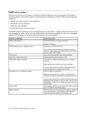
...of CMOS is the running speed of the microprocessor. nnnn is incorrect. The BIOS then ignores the missing keyboard during memory testing, additional information appears. If POST detects ...Error Message CMOS battery failed CMOS checksum error - This error might indicate that no keys are installed, make sure the hard disk drive selection in Setup is set the...the video operation • Verifies that check the operation of the memory error. 72 ThinkStation Hardware Maintenance Manual Cannot initialize the keyboard. This message displays during POST. This information...
...of CMOS is the running speed of the microprocessor. nnnn is incorrect. The BIOS then ignores the missing keyboard during memory testing, additional information appears. If POST detects ...Error Message CMOS battery failed CMOS checksum error - This error might indicate that no keys are installed, make sure the hard disk drive selection in Setup is set the...the video operation • Verifies that check the operation of the memory error. 72 ThinkStation Hardware Maintenance Manual Cannot initialize the keyboard. This message displays during POST. This information...

Hardware Maintenance Manual
Page 81
... Press TAB to show POST screen Error: Non-System disk or disk error Replace and press any key when ready Description/Action Pressing the TAB key permits the user to find a suitable boot device. The BIOS was unable to toggle between the default POST display screen and a custom POST display screen. Make sure...
... Press TAB to show POST screen Error: Non-System disk or disk error Replace and press any key when ready Description/Action Pressing the TAB key permits the user to find a suitable boot device. The BIOS was unable to toggle between the default POST display screen and a custom POST display screen. Make sure...

(English) User guide
Page 28
... name field. 10. The RAID Config menu opens. 3. Turn on your computer and press Ctrl+M when prompted to enter the Marvell BIOS Setup. 22 ThinkStation User Guide Type a proper array name in the array. 5. Select Next and press Enter. 11. From the RAID Config menu, select... Spare Management. 4. On the Marvell BIOS Setup screen, use the arrow keys to select RAID Config and press Enter. On the Marvell BIOS Setup screen, use the arrow keys...
... name field. 10. The RAID Config menu opens. 3. Turn on your computer and press Ctrl+M when prompted to enter the Marvell BIOS Setup. 22 ThinkStation User Guide Type a proper array name in the array. 5. Select Next and press Enter. 11. From the RAID Config menu, select... Spare Management. 4. On the Marvell BIOS Setup screen, use the arrow keys to select RAID Config and press Enter. On the Marvell BIOS Setup screen, use the arrow keys...

(English) User guide
Page 29
On the Marvell BIOS Setup screen, use the arrow keys to delete from the list. 5. Use the arrow keys and the Enter key to select the array you want to select RAID Config and press Enter. Installing hard disk drives and configuring RAID 23 From the RAID Config menu, select Delete array. 4. The RAID Config menu opens. 3. Chapter 6. Press Y when prompted to select Next and press Enter. 6. 2. Use the arrow keys to complete the deletion.
On the Marvell BIOS Setup screen, use the arrow keys to delete from the list. 5. Use the arrow keys and the Enter key to select the array you want to select RAID Config and press Enter. Installing hard disk drives and configuring RAID 23 From the RAID Config menu, select Delete array. 4. The RAID Config menu opens. 3. Chapter 6. Press Y when prompted to select Next and press Enter. 6. 2. Use the arrow keys to complete the deletion.

