Hardware Maintenance Manual
Page 1
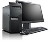
ThinkCentre Hardware Maintenance Manual Machine Types: 0267, 0268, 0385, 1730, 1981, 1943, 4166, 4167, 4169, 5025, 5030, 5032, 5048, 5049, 5069, 5070, 7517, and 7518
ThinkCentre Hardware Maintenance Manual Machine Types: 0267, 0268, 0385, 1730, 1981, 1943, 4166, 4167, 4169, 5025, 5030, 5032, 5048, 5049, 5069, 5070, 7517, and 7518
Hardware Maintenance Manual
Page 3
...47 Chapter 7. General checkout . . . . . 37 Problem determination tips 37 Chapter 5. Diagnostic programs . . . 39 Lenovo ThinkVantage Toolbox 39 Lenovo Solution Center 39 PC-Doctor for DOS 40 Creating a diagnostic disc 40 Running the diagnostic program from the diagnostic disc 40 ... Tools 33 ThinkVantage Productivity Center 33 Lenovo Solution Center 34 SimpleTap 34 Additional information resources 34 Specifications 34 For machine types: 0268, 1730, 1943, 4166, 4169, 5030, 5048, 5069, and 7517. . . . . . 35 For machine types: 0267, 0385, 1981, 4167, 5025, 5032, 5049, 5070, and 7518. ...
...47 Chapter 7. General checkout . . . . . 37 Problem determination tips 37 Chapter 5. Diagnostic programs . . . 39 Lenovo ThinkVantage Toolbox 39 Lenovo Solution Center 39 PC-Doctor for DOS 40 Creating a diagnostic disc 40 Running the diagnostic program from the diagnostic disc 40 ... Tools 33 ThinkVantage Productivity Center 33 Lenovo Solution Center 34 SimpleTap 34 Additional information resources 34 Specifications 34 For machine types: 0268, 1730, 1943, 4166, 4169, 5030, 5048, 5069, and 7517. . . . . . 35 For machine types: 0267, 0385, 1981, 4167, 5025, 5032, 5049, 5070, and 7518. ...
Hardware Maintenance Manual
Page 4
... 5032, 5049, 5070, and 7518 163 Mechanical FRUs 178 Keyboard and Mouse 185 Adapters and miscellaneous FRUs 228 Power Cords 232 Recovery discs 241 ii ThinkCentre Hardware Maintenance Manual Windows 7 Home Premium 32 Recovery CD 241 Windows 7 Professional 32 Recovery CD . . 244 Windows 7 Professional 64 Recovery CD ...Business 32 Recovery CD . . 268 Windows Vista Home Basic 32 Recovery CD 269 Overall: 0268, 1730, 1943, 4166, 4169, 5030, 5048, 5069, and 7517 271 Mechanical FRUs 283 Keyboard and Mouse 290 Adapters and miscellaneous FRUs 327 Power Cords 330 Recovery discs 338 Windows 7 ...
... 5032, 5049, 5070, and 7518 163 Mechanical FRUs 178 Keyboard and Mouse 185 Adapters and miscellaneous FRUs 228 Power Cords 232 Recovery discs 241 ii ThinkCentre Hardware Maintenance Manual Windows 7 Home Premium 32 Recovery CD 241 Windows 7 Professional 32 Recovery CD . . 244 Windows 7 Professional 64 Recovery CD ...Business 32 Recovery CD . . 268 Windows Vista Home Basic 32 Recovery CD 269 Overall: 0268, 1730, 1943, 4166, 4169, 5030, 5048, 5069, and 7517 271 Mechanical FRUs 283 Keyboard and Mouse 290 Adapters and miscellaneous FRUs 327 Power Cords 330 Recovery discs 338 Windows 7 ...
Hardware Maintenance Manual
Page 41
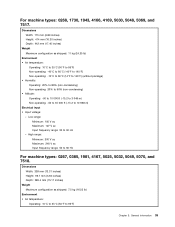
... V ac Maximum: 127 V ac Input frequency range: 50 to 10 668 m) Electrical input • Input voltage: - For machine types: 0268, 1730, 1943, 4166, 4169, 5030, 5048, 5069, and 7517.
... V ac Maximum: 127 V ac Input frequency range: 50 to 10 668 m) Electrical input • Input voltage: - For machine types: 0268, 1730, 1943, 4166, 4169, 5030, 5048, 5069, and 7517.
Hardware Maintenance Manual
Page 51
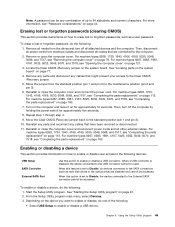
... page 44. See "Locating parts on the system board" on the system board. For machine types 0268, 1730, 1943, 4166, 4169, 5030, 5048, 5069, and 7517, see "Password considerations" on page 113. Move the Clear CMOS /Recovery jumper back to enable or disable a USB connector. Chapter... lost or forgotten passwords (clearing CMOS) This section provides instructions on page 113. For machine types 0268, 1730, 1943, 4166, 4169, 5030, 5048, 5069, and 7517, see "Completing the parts replacement" on how to erase lost or forgotten password, do the following: 1. For machine types 0267...
... page 44. See "Locating parts on the system board" on the system board. For machine types 0268, 1730, 1943, 4166, 4169, 5030, 5048, 5069, and 7517, see "Password considerations" on page 113. Move the Clear CMOS /Recovery jumper back to enable or disable a USB connector. Chapter... lost or forgotten passwords (clearing CMOS) This section provides instructions on page 113. For machine types 0268, 1730, 1943, 4166, 4169, 5030, 5048, 5069, and 7517, see "Completing the parts replacement" on how to erase lost or forgotten password, do the following: 1. For machine types 0267...
Hardware Maintenance Manual
Page 79
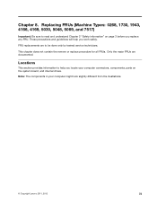
..., 1730, 1943, 4166, 4169, 5030, 5048, 5069, and 7517) Important: Be sure to read and understand Chapter 2 "Safety information" on the system board, and internal drives. These precautions and guidelines will help you locate your computer might look slightly different from the illustrations. © Copyright Lenovo 2011, 2012 73 This chapter does...
..., 1730, 1943, 4166, 4169, 5030, 5048, 5069, and 7517) Important: Be sure to read and understand Chapter 2 "Safety information" on the system board, and internal drives. These precautions and guidelines will help you locate your computer might look slightly different from the illustrations. © Copyright Lenovo 2011, 2012 73 This chapter does...
Hardware Maintenance Manual
Page 81
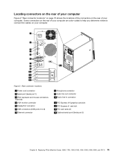
... connect the cables on the rear of your computer. Figure 2. Some connectors on your computer. Replacing FRUs (Machine Types: 0268, 1730, 1943, 4166, 4169, 5030, 5048, 5069, and 7517) 75
... connect the cables on the rear of your computer. Figure 2. Some connectors on your computer. Replacing FRUs (Machine Types: 0268, 1730, 1943, 4166, 4169, 5030, 5048, 5069, and 7517) 75
Hardware Maintenance Manual
Page 83
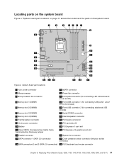
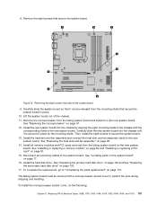
Figure 4. Replacing FRUs (Machine Types: 0268, 1730, 1943, 4166, 4169, 5030, 5048, 5069, and 7517) 77 Locating parts on the system board Figure 4 "System board part locations" on page 77 shows the locations of the parts on ...
Figure 4. Replacing FRUs (Machine Types: 0268, 1730, 1943, 4166, 4169, 5030, 5048, 5069, and 7517) 77 Locating parts on the system board Figure 4 "System board part locations" on page 77 shows the locations of the parts on ...
Hardware Maintenance Manual
Page 85
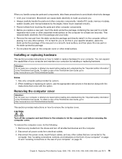
... hardware This section provides instructions on how to remove the computer cover. To obtain a copy of the ThinkCentre User Guide, go to: http://www.lenovo.com/ThinkCentreUserGuides This section provides instructions on how to install or replace hardware for your computer" on the ... 1730, 1943, 4166, 4169, 5030, 5048, 5069, and 7517) 79 Handle PCI cards, memory modules, system boards, and microprocessors by Lenovo. 2. Chapter 8. This reduces static electricity from the static-protective package and directly install it in the ThinkCentre User Guide. Use only computer parts provided ...
... hardware This section provides instructions on how to remove the computer cover. To obtain a copy of the ThinkCentre User Guide, go to: http://www.lenovo.com/ThinkCentreUserGuides This section provides instructions on how to install or replace hardware for your computer" on the ... 1730, 1943, 4166, 4169, 5030, 5048, 5069, and 7517) 79 Handle PCI cards, memory modules, system boards, and microprocessors by Lenovo. 2. Chapter 8. This reduces static electricity from the static-protective package and directly install it in the ThinkCentre User Guide. Use only computer parts provided ...
Hardware Maintenance Manual
Page 87
... safety information" in the chassis, then pivot the front bezel inwards until it snaps into position on how to : http://www.lenovo.com/ThinkCentreUserGuides This section provides instructions on the left side and pivoting the front bezel outward. Turn off the computer and disconnect all... Figure 7. To obtain a copy of the front bezel with the corresponding holes in the ThinkCentre User Guide. Remove the computer cover. Chapter 8. Replacing FRUs (Machine Types: 0268, 1730, 1943, 4166, 4169, 5030, 5048, 5069, and 7517) 81 To reinstall the front bezel, align the three plastic tabs ...
... safety information" in the chassis, then pivot the front bezel inwards until it snaps into position on how to : http://www.lenovo.com/ThinkCentreUserGuides This section provides instructions on the left side and pivoting the front bezel outward. Turn off the computer and disconnect all... Figure 7. To obtain a copy of the front bezel with the corresponding holes in the ThinkCentre User Guide. Remove the computer cover. Chapter 8. Replacing FRUs (Machine Types: 0268, 1730, 1943, 4166, 4169, 5030, 5048, 5069, and 7517) 81 To reinstall the front bezel, align the three plastic tabs ...
Hardware Maintenance Manual
Page 89
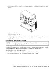
... the card slot. Chapter 8. The card fits tightly into the appropriate slot on page 77. Replacing FRUs (Machine Types: 0268, 1730, 1943, 4166, 4169, 5030, 5048, 5069, and 7517) 83 Note: If you are installing a PCI Express x16 graphics card, make sure the memory slot retaining clips are closed before you...
... the card slot. Chapter 8. The card fits tightly into the appropriate slot on page 77. Replacing FRUs (Machine Types: 0268, 1730, 1943, 4166, 4169, 5030, 5048, 5069, and 7517) 83 Note: If you are installing a PCI Express x16 graphics card, make sure the memory slot retaining clips are closed before you...
Hardware Maintenance Manual
Page 91
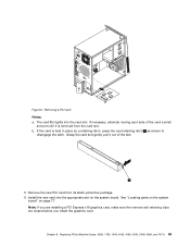
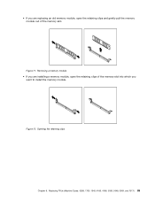
Removing a memory module • If you are replacing an old memory module, open the retaining clips of the memory slot into which you are installing a memory module, open the retaining clips and gently pull the memory module out of the memory slot. Figure 12. Figure 11. Replacing FRUs (Machine Types: 0268, 1730, 1943, 4166, 4169, 5030, 5048, 5069, and 7517) 85 Opening the retaining clips Chapter 8. • If you want to install the memory module.
Removing a memory module • If you are replacing an old memory module, open the retaining clips of the memory slot into which you are installing a memory module, open the retaining clips and gently pull the memory module out of the memory slot. Figure 12. Figure 11. Replacing FRUs (Machine Types: 0268, 1730, 1943, 4166, 4169, 5030, 5048, 5069, and 7517) 85 Opening the retaining clips Chapter 8. • If you want to install the memory module.
Hardware Maintenance Manual
Page 93
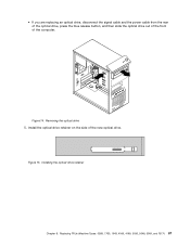
Removing the optical drive 5. Installing the optical drive retainer Chapter 8. Replacing FRUs (Machine Types: 0268, 1730, 1943, 4166, 4169, 5030, 5048, 5069, and 7517) 87 Figure 15. Install the optical drive retainer on the side of the computer. Figure 14. • If you are replacing an optical drive, disconnect the signal cable and the power cable from the rear of the optical drive, press the blue release button, and then slide the optical drive out of the front of the new optical drive.
Removing the optical drive 5. Installing the optical drive retainer Chapter 8. Replacing FRUs (Machine Types: 0268, 1730, 1943, 4166, 4169, 5030, 5048, 5069, and 7517) 87 Figure 15. Install the optical drive retainer on the side of the computer. Figure 14. • If you are replacing an optical drive, disconnect the signal cable and the power cable from the rear of the optical drive, press the blue release button, and then slide the optical drive out of the front of the new optical drive.

Hardware Maintenance Manual
Page 95
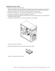
... reader retainer to the computer. 2. Remove the computer cover. Locate the card reader drive bay. Replacing FRUs (Machine Types: 0268, 1730, 1943, 4166, 4169, 5030, 5048, 5069, and 7517) 89 Remove all media from electrical outlets and disconnect all attached devices and the computer. See "Removing and reinstalling the front bezel...
... reader retainer to the computer. 2. Remove the computer cover. Locate the card reader drive bay. Replacing FRUs (Machine Types: 0268, 1730, 1943, 4166, 4169, 5030, 5048, 5069, and 7517) 89 Remove all media from electrical outlets and disconnect all attached devices and the computer. See "Removing and reinstalling the front bezel...
Hardware Maintenance Manual
Page 97
... reader out of the new card reader. Locate the card reader. Removing the card reader 7. Replacing FRUs (Machine Types: 0268, 1730, 1943, 4166, 4169, 5030, 5048, 5069, and 7517) 91 Replacing the card reader To replace the card reader, do the following: 1. Figure 22. Figure 23. See "Locating components" on page...
... reader out of the new card reader. Locate the card reader. Removing the card reader 7. Replacing FRUs (Machine Types: 0268, 1730, 1943, 4166, 4169, 5030, 5048, 5069, and 7517) 91 Replacing the card reader To replace the card reader, do the following: 1. Figure 22. Figure 23. See "Locating components" on page...

Hardware Maintenance Manual
Page 99
... Locate the battery. See "Locating parts on the system board" on page 113. 9. To obtain a copy of the ThinkCentre User Guide, go to: http://www.lenovo.com/ThinkCentreUserGuides This section provides instructions on page 43. Use the Setup Utility program to replace the power supply assembly. See Chapter...are required for the first time after replacing the battery. 10. Replacing FRUs (Machine Types: 0268, 1730, 1943, 4166, 4169, 5030, 5048, 5069, and 7517) 93 Reinstall any parts and reconnect any cables that have been removed or disconnected. 8. 3. Removing the old battery 6.
... Locate the battery. See "Locating parts on the system board" on page 113. 9. To obtain a copy of the ThinkCentre User Guide, go to: http://www.lenovo.com/ThinkCentreUserGuides This section provides instructions on page 43. Use the Setup Utility program to replace the power supply assembly. See Chapter...are required for the first time after replacing the battery. 10. Replacing FRUs (Machine Types: 0268, 1730, 1943, 4166, 4169, 5030, 5048, 5069, and 7517) 93 Reinstall any parts and reconnect any cables that have been removed or disconnected. 8. 3. Removing the old battery 6.
Hardware Maintenance Manual
Page 101
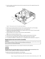
...disconnect all power cords from electrical outlets. Figure 27. To obtain a copy of the ThinkCentre User Guide, go to let the computer cool before reading and understanding the "Important safety information" in the ThinkCentre User Guide. To replace the heat sink and fan assembly, do the following: 1.... in the chassis. 12. Chapter 8. Replacing FRUs (Machine Types: 0268, 1730, 1943, 4166, 4169, 5030, 5048, 5069, and 7517) 95 Note: Use only screws provided by Lenovo. 10. Removing the screws for the power supply assembly 6. Turn off the computer and wait three to five minutes ...
...disconnect all power cords from electrical outlets. Figure 27. To obtain a copy of the ThinkCentre User Guide, go to let the computer cool before reading and understanding the "Important safety information" in the ThinkCentre User Guide. To replace the heat sink and fan assembly, do the following: 1.... in the chassis. 12. Chapter 8. Replacing FRUs (Machine Types: 0268, 1730, 1943, 4166, 4169, 5030, 5048, 5069, and 7517) 95 Note: Use only screws provided by Lenovo. 10. Removing the screws for the power supply assembly 6. Turn off the computer and wait three to five minutes ...

Hardware Maintenance Manual
Page 103
...electrical outlets and disconnect all power cords from the drives and turn off the computer and wait three to five minutes to : http://www.lenovo.com/ThinkCentreUserGuides This section provides instructions on page 79. 3. See "Locating parts on the system board" on page 77. 11. Connect the...to replace the microprocessor. Chapter 8. Replacing FRUs (Machine Types: 0268, 1730, 1943, 4166, 4169, 5030, 5048, 5069, and 7517) 97 To obtain a copy of it does not get in the ThinkCentre User Guide. See "Removing the computer cover" on how to the computer. 2. Locate the system board and ...
...electrical outlets and disconnect all power cords from the drives and turn off the computer and wait three to five minutes to : http://www.lenovo.com/ThinkCentreUserGuides This section provides instructions on page 79. 3. See "Locating parts on the system board" on page 77. 11. Connect the...to replace the microprocessor. Chapter 8. Replacing FRUs (Machine Types: 0268, 1730, 1943, 4166, 4169, 5030, 5048, 5069, and 7517) 97 To obtain a copy of it does not get in the ThinkCentre User Guide. See "Removing the computer cover" on how to the computer. 2. Locate the system board and ...
Hardware Maintenance Manual
Page 105
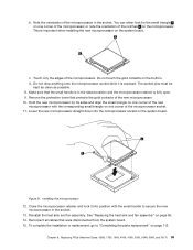
... on the system board. See "Replacing the heat sink and fan assembly" on the bottom. Replacing FRUs (Machine Types: 0268, 1730, 1943, 4166, 4169, 5030, 5048, 5069, and 7517) 99 Touch only the edges of the microprocessor socket. 11. Installing the microprocessor 12. The socket pins must be kept as clean...
... on the system board. See "Replacing the heat sink and fan assembly" on the bottom. Replacing FRUs (Machine Types: 0268, 1730, 1943, 4166, 4169, 5030, 5048, 5069, and 7517) 99 Touch only the edges of the microprocessor socket. 11. Installing the microprocessor 12. The socket pins must be kept as clean...
Hardware Maintenance Manual
Page 107
... is secured in place by aligning the eight mounting studs in the new system board. Replacing FRUs (Machine Types: 0268, 1730, 1943, 4166, 4169, 5030, 5048, 5069, and 7517) 101
... is secured in place by aligning the eight mounting studs in the new system board. Replacing FRUs (Machine Types: 0268, 1730, 1943, 4166, 4169, 5030, 5048, 5069, and 7517) 101