
Hardware Maintenance Manual
Page 1
ThinkCentre Hardware Maintenance Manual Machine Types: 0267, 0268, 0385, 1730, 1981, 1943, 4166, 4167, 4169, 5025, 5030, 5032, 5048, 5049, 5069, 5070, 7517, and 7518
ThinkCentre Hardware Maintenance Manual Machine Types: 0267, 0268, 0385, 1730, 1981, 1943, 4166, 4167, 4169, 5025, 5030, 5032, 5048, 5049, 5069, 5070, 7517, and 7518
Hardware Maintenance Manual
Page 3
...Miscellaneous error messages 69 Undetermined problems 71 Chapter 8. General information . . . . 33 Lenovo Welcome 33 Lenovo ThinkVantage Tools 33 ThinkVantage Productivity Center 33 Lenovo Solution Center 34 SimpleTap 34 Additional information resources 34 Specifications 34 For machine types: 0268,.... . 35 For machine types: 0267, 0385, 1981, 4167, 5025, 5032, 5049, 5070, and 7518. . . . . . 35 Chapter 4. Diagnostic programs . . . 39 Lenovo ThinkVantage Toolbox 39 Lenovo Solution Center 39 PC-Doctor for DOS 40 Creating a diagnostic disc 40 Running the diagnostic program from the ...
...Miscellaneous error messages 69 Undetermined problems 71 Chapter 8. General information . . . . 33 Lenovo Welcome 33 Lenovo ThinkVantage Tools 33 ThinkVantage Productivity Center 33 Lenovo Solution Center 34 SimpleTap 34 Additional information resources 34 Specifications 34 For machine types: 0268,.... . 35 For machine types: 0267, 0385, 1981, 4167, 5025, 5032, 5049, 5070, and 7518. . . . . . 35 Chapter 4. Diagnostic programs . . . 39 Lenovo ThinkVantage Toolbox 39 Lenovo Solution Center 39 PC-Doctor for DOS 40 Creating a diagnostic disc 40 Running the diagnostic program from the ...
Hardware Maintenance Manual
Page 4
Replacing FRUs (Machine Types: 0267, 0385, 1981, 4167, 5025, 5032, 5049, 5070, and 7518) . . . . . 115 Locations 115 Locating connectors, controls, and indicators on the front of your computer 116 Locating connectors on the rear of your operating system 366 ... 10. FRU lists 163 Overall: MT 0267, 0385, 1981, 4167, 5025, 5032, 5049, 5070, and 7518 163 Mechanical FRUs 178 Keyboard and Mouse 185 Adapters and miscellaneous FRUs 228 Power Cords 232 Recovery discs 241 ii ThinkCentre Hardware Maintenance Manual Windows 7 Home Premium 32 Recovery CD 241 Windows 7 Professional 32 Recovery CD...
Replacing FRUs (Machine Types: 0267, 0385, 1981, 4167, 5025, 5032, 5049, 5070, and 7518) . . . . . 115 Locations 115 Locating connectors, controls, and indicators on the front of your computer 116 Locating connectors on the rear of your operating system 366 ... 10. FRU lists 163 Overall: MT 0267, 0385, 1981, 4167, 5025, 5032, 5049, 5070, and 7518 163 Mechanical FRUs 178 Keyboard and Mouse 185 Adapters and miscellaneous FRUs 228 Power Cords 232 Recovery discs 241 ii ThinkCentre Hardware Maintenance Manual Windows 7 Home Premium 32 Recovery CD 241 Windows 7 Professional 32 Recovery CD...
Hardware Maintenance Manual
Page 41
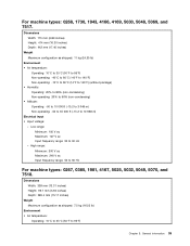
...: Minimum: 100 V ac Maximum: 127 V ac Input frequency range: 50 to 60 Hz For machine types: 0267, 0385, 1981, 4167, 5025, 5032, 5049, 5070, and 7518. Dimensions Width: 338 mm (13.31 inches) Height: 99.7 mm (3.93 inches) Depth: 385.4 mm (15.17 inches) Weight Maximum configuration as shipped: 11 kg...
...: Minimum: 100 V ac Maximum: 127 V ac Input frequency range: 50 to 60 Hz For machine types: 0267, 0385, 1981, 4167, 5025, 5032, 5049, 5070, and 7518. Dimensions Width: 338 mm (13.31 inches) Height: 99.7 mm (3.93 inches) Depth: 385.4 mm (15.17 inches) Weight Maximum configuration as shipped: 11 kg...
Hardware Maintenance Manual
Page 51
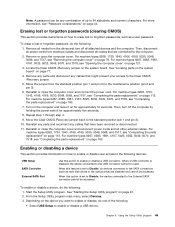
... off all cables that have been removed or disconnected. 11. For machine types 0267, 0385, 1981, 4167, 5025, 5032, 5049, 5070, and 7518, see "Completing the parts replacement" on page 79. Then, turn off the computer by holding the power switch for approximately 10 seconds. Start the ...and connect the power cord. Remove or open the computer cover. For machine types 0267, 0385, 1981, 4167, 5025, 5032, 5049, 5070, and 7518, see "Completing the parts replacement" on page 43. 2. Erasing lost or forgotten passwords, such as hard disk drives or the optical drive) are connected...
... off all cables that have been removed or disconnected. 11. For machine types 0267, 0385, 1981, 4167, 5025, 5032, 5049, 5070, and 7518, see "Completing the parts replacement" on page 79. Then, turn off the computer by holding the power switch for approximately 10 seconds. Start the ...and connect the power cord. Remove or open the computer cover. For machine types 0267, 0385, 1981, 4167, 5025, 5032, 5049, 5070, and 7518, see "Completing the parts replacement" on page 43. 2. Erasing lost or forgotten passwords, such as hard disk drives or the optical drive) are connected...

Hardware Maintenance Manual
Page 121
Chapter 9. These precautions and guidelines will help you locate your computer might look slightly different from the illustrations. © Copyright Lenovo 2011, 2012 115 Note: The components in your computer connectors, components, parts on page 3 before you work safely. Replacing FRUs ...(Machine Types: 0267, 0385, 1981, 4167, 5025, 5032, 5049, 5070, and 7518) Important: Be sure to read and understand Chapter 2 "Safety information" on the system board, and internal drives. FRU replacements are documented. This chapter...
Chapter 9. These precautions and guidelines will help you locate your computer might look slightly different from the illustrations. © Copyright Lenovo 2011, 2012 115 Note: The components in your computer connectors, components, parts on page 3 before you work safely. Replacing FRUs ...(Machine Types: 0267, 0385, 1981, 4167, 5025, 5032, 5049, 5070, and 7518) Important: Be sure to read and understand Chapter 2 "Safety information" on the system board, and internal drives. FRU replacements are documented. This chapter...

Hardware Maintenance Manual
Page 123
Replacing FRUs (Machine Types: 0267, 0385, 1981, 4167, 5025, 5032, 5049, 5070, and 7518) 117 Figure 50. Locating connectors on the rear of your computer Figure 50 "Rear connector locations" on page 117 shows the locations of the connectors ...
Replacing FRUs (Machine Types: 0267, 0385, 1981, 4167, 5025, 5032, 5049, 5070, and 7518) 117 Figure 50. Locating connectors on the rear of your computer Figure 50 "Rear connector locations" on page 117 shows the locations of the connectors ...

Hardware Maintenance Manual
Page 125
... SATA connectors 2 and 3 (SATA 2.0 connectors) 28 PS/2 keyboard and mouse connector Chapter 9. Replacing FRUs (Machine Types: 0267, 0385, 1981, 4167, 5025, 5032, 5049, 5070, and 7518) 119 Figure 52.
... SATA connectors 2 and 3 (SATA 2.0 connectors) 28 PS/2 keyboard and mouse connector Chapter 9. Replacing FRUs (Machine Types: 0267, 0385, 1981, 4167, 5025, 5032, 5049, 5070, and 7518) 119 Figure 52.

Hardware Maintenance Manual
Page 127
...0385, 1981, 4167, 5025, 5032, 5049, 5070, and 7518) 121 Never touch exposed circuitry. • Prevent others from the drives and turn off the computer and wait three to five minutes to : http://www.lenovo.com/ThinkCentreUserGuides Notes: 1. Opening the computer cover Attention: Do ...place the part on any repair before reading and understanding the "Important safety information" in the ThinkCentre User Guide. Handle PCI cards, memory modules, system boards, and microprocessors by Lenovo. 2. Remove any other computer components. Attention: Do not open the computer cover, do this ...
...0385, 1981, 4167, 5025, 5032, 5049, 5070, and 7518) 121 Never touch exposed circuitry. • Prevent others from the drives and turn off the computer and wait three to five minutes to : http://www.lenovo.com/ThinkCentreUserGuides Notes: 1. Opening the computer cover Attention: Do ...place the part on any repair before reading and understanding the "Important safety information" in the ThinkCentre User Guide. Handle PCI cards, memory modules, system boards, and microprocessors by Lenovo. 2. Remove any other computer components. Attention: Do not open the computer cover, do this ...

Hardware Maintenance Manual
Page 129
Replacing FRUs (Machine Types: 0267, 0385, 1981, 4167, 5025, 5032, 5049, 5070, and 7518) 123 Remove the front bezel by releasing the three plastic tabs on the top of the front bezel and pivoting the front bezel outward to remove it from the computer. Figure 55. Removing the front bezel Chapter 9. 3.
Replacing FRUs (Machine Types: 0267, 0385, 1981, 4167, 5025, 5032, 5049, 5070, and 7518) 123 Remove the front bezel by releasing the three plastic tabs on the top of the front bezel and pivoting the front bezel outward to remove it from the computer. Figure 55. Removing the front bezel Chapter 9. 3.

Hardware Maintenance Manual
Page 131
... the front bezel. Remove any repair before reading and understanding the "Important safety information" in the ThinkCentre User Guide. Replacing FRUs (Machine Types: 0267, 0385, 1981, 4167, 5025, 5032, 5049, 5070, and 7518) 125 Installing or replacing a memory module Attention: Do not open the retaining clips and gently pull...any parts that provide up to a maximum of 32 GB. • Install memory modules in any combination up to a maximum of the ThinkCentre User Guide, go to: http://www.lenovo.com/ThinkCentreUserGuides This section provides instructions on how to the memory slots.
... the front bezel. Remove any repair before reading and understanding the "Important safety information" in the ThinkCentre User Guide. Replacing FRUs (Machine Types: 0267, 0385, 1981, 4167, 5025, 5032, 5049, 5070, and 7518) 125 Installing or replacing a memory module Attention: Do not open the retaining clips and gently pull...any parts that provide up to a maximum of 32 GB. • Install memory modules in any combination up to a maximum of the ThinkCentre User Guide, go to: http://www.lenovo.com/ThinkCentreUserGuides This section provides instructions on how to the memory slots.

Hardware Maintenance Manual
Page 133
... to disengage the latch. The card fits tightly into the card slot. Replacing FRUs (Machine Types: 0267, 0385, 1981, 4167, 5025, 5032, 5049, 5070, and 7518) 127 Removing a PCI card Notes: a. Remove the new PCI card from the card slot.
... to disengage the latch. The card fits tightly into the card slot. Replacing FRUs (Machine Types: 0267, 0385, 1981, 4167, 5025, 5032, 5049, 5070, and 7518) 127 Removing a PCI card Notes: a. Remove the new PCI card from the card slot.

Hardware Maintenance Manual
Page 135
Then install the two screws to secure the card reader to the chassis. Install the card reader bracket to the bracket. 6. Installing the card reader Chapter 9. Replacing FRUs (Machine Types: 0267, 0385, 1981, 4167, 5025, 5032, 5049, 5070, and 7518) 129 Figure 62. Then push the bracket to the left to align the screw hole in the bracket with the corresponding hole in the chassis. 5. Install the new card reader into the card reader bracket.
Then install the two screws to secure the card reader to the chassis. Install the card reader bracket to the bracket. 6. Installing the card reader Chapter 9. Replacing FRUs (Machine Types: 0267, 0385, 1981, 4167, 5025, 5032, 5049, 5070, and 7518) 129 Figure 62. Then push the bracket to the left to align the screw hole in the bracket with the corresponding hole in the chassis. 5. Install the new card reader into the card reader bracket.

Hardware Maintenance Manual
Page 137
..." on page 77. 6. Removing the screw that secures the card reader bracket. 1. Replacing FRUs (Machine Types: 0267, 0385, 1981, 4167, 5025, 5032, 5049, 5070, and 7518) 131 Remove the screw that secures the card reader 7.
..." on page 77. 6. Removing the screw that secures the card reader bracket. 1. Replacing FRUs (Machine Types: 0267, 0385, 1981, 4167, 5025, 5032, 5049, 5070, and 7518) 131 Remove the screw that secures the card reader 7.

Hardware Maintenance Manual
Page 139
... maintains the date, time, and configuration information for built-in the ThinkCentre User Guide. Reinstall the front bezel. Replacing FRUs (Machine Types: 0267, 0385, 1981, 4167, 5025, 5032, 5049, 5070, and 7518) 133 Before performing the following : Chapter 9. To complete the installation... or replacement, go to: http://www.lenovo.com/ThinkCentreUserGuides Your computer has a special type of the ThinkCentre User Guide, go to the chassis. See "Removing and...
... maintains the date, time, and configuration information for built-in the ThinkCentre User Guide. Reinstall the front bezel. Replacing FRUs (Machine Types: 0267, 0385, 1981, 4167, 5025, 5032, 5049, 5070, and 7518) 133 Before performing the following : Chapter 9. To complete the installation... or replacement, go to: http://www.lenovo.com/ThinkCentreUserGuides Your computer has a special type of the ThinkCentre User Guide, go to the chassis. See "Removing and...

Hardware Maintenance Manual
Page 141
4. Disconnect the signal cable and the power cable from the hard disk drive to remove the hard disk drive from the chassis. 6. Replacing FRUs (Machine Types: 0267, 0385, 1981, 4167, 5025, 5032, 5049, 5070, and 7518) 135 Figure 71. Pull on the handle of the hard disk drive bracket as shown to completely remove the hard disk drive from the bracket. Figure 70. Removing the hard disk drive 5. Removing the hard disk drive from the optical drive bay. Flex the retaining clips as shown and then lift the hard disk drive bracket up from the bracket Chapter 9.
4. Disconnect the signal cable and the power cable from the hard disk drive to remove the hard disk drive from the chassis. 6. Replacing FRUs (Machine Types: 0267, 0385, 1981, 4167, 5025, 5032, 5049, 5070, and 7518) 135 Figure 71. Pull on the handle of the hard disk drive bracket as shown to completely remove the hard disk drive from the bracket. Figure 70. Removing the hard disk drive 5. Removing the hard disk drive from the optical drive bay. Flex the retaining clips as shown and then lift the hard disk drive bracket up from the bracket Chapter 9.

Hardware Maintenance Manual
Page 143
...Machine Types: 0267, 0385, 1981, 4167, 5025, 5032, 5049, 5070, and 7518) 137 To obtain a copy of the optical drive. Turn off the computer and disconnect all power cords from the rear of the ThinkCentre User Guide, go to "Completing the parts replacement" on page 160. Figure 73.... Chapter 9. Remove the hard disk drive. To replace the optical drive, do the following: 1. To complete the installation or replacement, go to: http://www.lenovo.com/ThinkCentreUserGuides This ...
...Machine Types: 0267, 0385, 1981, 4167, 5025, 5032, 5049, 5070, and 7518) 137 To obtain a copy of the optical drive. Turn off the computer and disconnect all power cords from the rear of the ThinkCentre User Guide, go to "Completing the parts replacement" on page 160. Figure 73.... Chapter 9. Remove the hard disk drive. To replace the optical drive, do the following: 1. To complete the installation or replacement, go to: http://www.lenovo.com/ThinkCentreUserGuides This ...

Hardware Maintenance Manual
Page 145
...to let the computer cool before reading and understanding the "Important safety information" in the ThinkCentre User Guide. Chapter 9. Replacing FRUs (Machine Types: 0267, 0385, 1981, 4167, 5025, 5032, 5049, 5070, and 7518) 139 9. To replace the heat sink and fan assembly, do the following: 1. ... microprocessor fan connector on page 121. 3. Then, disconnect all cables that are connected to the rear of the ThinkCentre User Guide, go to : http://www.lenovo.com/ThinkCentreUserGuides This section provides instructions on page 77. See "Opening the computer cover" on the system board. ...
...to let the computer cool before reading and understanding the "Important safety information" in the ThinkCentre User Guide. Chapter 9. Replacing FRUs (Machine Types: 0267, 0385, 1981, 4167, 5025, 5032, 5049, 5070, and 7518) 139 9. To replace the heat sink and fan assembly, do the following: 1. ... microprocessor fan connector on page 121. 3. Then, disconnect all cables that are connected to the rear of the ThinkCentre User Guide, go to : http://www.lenovo.com/ThinkCentreUserGuides This section provides instructions on page 77. See "Opening the computer cover" on the system board. ...

Hardware Maintenance Manual
Page 147
... heat sink fan duct from the failing heat sink and fan assembly. Replacing FRUs (Machine Types: 0267, 0385, 1981, 4167, 5025, 5032, 5049, 5070, and 7518) 141 Connect the new heat sink and fan assembly cable to secure the new heat sink and fan assembly, as shown in the system board...
... heat sink fan duct from the failing heat sink and fan assembly. Replacing FRUs (Machine Types: 0267, 0385, 1981, 4167, 5025, 5032, 5049, 5070, and 7518) 141 Connect the new heat sink and fan assembly cable to secure the new heat sink and fan assembly, as shown in the system board...

Hardware Maintenance Manual
Page 149
... components. To replace the power supply assembly, do the following label attached. Replacing FRUs (Machine Types: 0267, 0385, 1981, 4167, 5025, 5032, 5049, 5070, and 7518) 143 See "Removing and reinstalling the front bezel" on page 134. Chapter 9. There are connected to the computer. 2. Then, disconnect all power cords from the...
... components. To replace the power supply assembly, do the following label attached. Replacing FRUs (Machine Types: 0267, 0385, 1981, 4167, 5025, 5032, 5049, 5070, and 7518) 143 See "Removing and reinstalling the front bezel" on page 134. Chapter 9. There are connected to the computer. 2. Then, disconnect all power cords from the...